-
1Step 1
BUILDING IT
You'll need a mini DIN 6-pin socket to connect to the keyboard. It can be scrounged from an old keyboard adapter, or you can eliminate it altogether by cutting the connector off the keyboard cable and wiring it directly to the interface. Refer to the PS/2 interfacing link at the bottom of this page for pinout information. The LED can be replaced with another color as long as the forward voltage at low current is 1.8-2.1 volts. The resistors are also not critical - any value from 2000 to 10,000 ohms should work, 1/10 watt or larger.
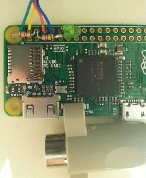
Solder the components directly to the GPIO connector holes like I did in the picture below. All connections are to the outside row of holes on the Zero. The LED's cathode is bent down and soldered in the fifth hole, the anode is soldered to a resistor. The keyboard data line is also soldered to this junction. The keyboard +5V line is soldered in the first hole, and the keyboard ground is soldered in the third hole. The keyboard clock line is soldered to the other resistor. Lastly the free ends of both resistors are bent round and soldered in the second hole on the Zero.
Make sure nothing connects where it shouldn't - a bit of paper or tape under everything will prevent this from happening. The picture is a bit fuzzy, but if you refer to the schematic and pinouts for the Pi it should become clear.
![]()
IMPORTANT: The keyboard should not be hot-plugged: connect or disconnect only when the Zero is powered off. Make sure you wire it correctly or you may fry your Zero, or the keyboard!
Source code is available under the files subpage. Don't be afraid of compiling kernel modules: easy module compiling instructions are available under my piModules page.
The device tree overlay
ps2pi-overlayin the files subpage needs to be copied to/boot/overlaysanddtoverlay=ps2pineeds to be added to/boot/config.txt. It will automatically load the kernel module as long as it's in the proper subdirectory in/lib/modulesanddepmodhas been run while you are in that directory.The overlay needs be configured with the clock divisor for the UART. To find this, connect the keyboard and power up. Then compile the ps2test program and run it as root. Follow the onscreen instructions to find the needed dividers. You'll have to edit the overlay source to set these values, then compile it. The overlay as supplied in the files section will work on an IBM Model M keyboard.
You also need to disable the serial console. The easiest way is to use raspi-config, and disable Serial under Advanced options.
The keyboard mapping is for a US keyboard. Other keyboards may need changes to the key map table in the overlay.
There is no reverse communication from the Pi to the keyboard so the keyboard lock lights do not function.
Here are links to sites that helped me in this project:
Dom and Gerts GPIO access example
Linux kernel module programming HOWTO

Discussions
Become a Hackaday.io Member
Create an account to leave a comment. Already have an account? Log In.