-
Hack Chat Transcript, Part 3
05/23/2019 at 20:07 • 0 comments![]() @oshpark hmm ... I have to overthink my approach :/ ... simplyfy my idea
@oshpark hmm ... I have to overthink my approach :/ ... simplyfy my idea![]() or a 0.25' wide by 8' long strip?
or a 0.25' wide by 8' long strip?![]() oops... inch.. "
oops... inch.. "![]() the maximum length of the panel is 16"
the maximum length of the panel is 16"![]() @Drew Fustini Hot damn.. I do have an idea... :)
@Drew Fustini Hot damn.. I do have an idea... :)![]() so that should be possible
so that should be possible![]() 2sq in is a little small for human interactable stuff (like my game controller) so I'm taking advantage of the 3x copies. My PCB will be double sided. One copy for each side of the controller
2sq in is a little small for human interactable stuff (like my game controller) so I'm taking advantage of the 3x copies. My PCB will be double sided. One copy for each side of the controller![]() We're getting up to the end of the hour, so I'm going to call official time and thank Drew and Chris for dropping by. They might need to get going, but feel free to hang around and answer questions if you like.
We're getting up to the end of the hour, so I'm going to call official time and thank Drew and Chris for dropping by. They might need to get going, but feel free to hang around and answer questions if you like.We'll be back on our regular Wednesday at noon Pacific schedule next week, with Spencer Owen talking about the RC2014, a Sinclair ZX80 clone.
https://hackaday.io/event/165304-retrocomputing-for-the-masses
![]() Thanks guys!
Thanks guys!![]() to wrap up, we are excited to see what new submissions are added to https://hackaday.io/contest/163267-flexible-pcb-concept-contest
to wrap up, we are excited to see what new submissions are added to https://hackaday.io/contest/163267-flexible-pcb-concept-contest![]() Thanks for answering our questions and making us dream
Thanks for answering our questions and making us dream![]() Thanks so much @Dan Malone and to everyone for their awesome questions about Flex!
Thanks so much @Dan Malone and to everyone for their awesome questions about Flex!![]() I'll post the chat transcript on the event page in a little bit.
I'll post the chat transcript on the event page in a little bit.![]() our flex PCB page:
our flex PCB page:https://docs.oshpark.com/services/flex/
![]() So many *Mind Blown* moments in just a few minutes ... has been a long time since i experienced that :)
So many *Mind Blown* moments in just a few minutes ... has been a long time since i experienced that :) -
Hack Chat Transcript Part 2
05/23/2019 at 20:04 • 0 comments![]() @Aaron_Kraus The substrate itself is spot-on 4.0 mils, which I've measured with a micrometer across multiple panel runs. The copper would likely be the largest variable, but should be with our stack-up specs https://docs.oshpark.com/services/flex/.
@Aaron_Kraus The substrate itself is spot-on 4.0 mils, which I've measured with a micrometer across multiple panel runs. The copper would likely be the largest variable, but should be with our stack-up specs https://docs.oshpark.com/services/flex/.![]() Gotcha, I'll throw something together. I'm curious to see how hard it would be to weld a stack of surface contact flex PCBs. Our ultrasonic welder is pretty old but has a decent sized jaw. Based off of the spec sheet I doubt we would be able to join more than 2-3 double sided but that could allow for water resistance.
Gotcha, I'll throw something together. I'm curious to see how hard it would be to weld a stack of surface contact flex PCBs. Our ultrasonic welder is pretty old but has a decent sized jaw. Based off of the spec sheet I doubt we would be able to join more than 2-3 double sided but that could allow for water resistance.![]() @oshpark @Dan Sheadel thx I missed that somehow :)
@oshpark @Dan Sheadel thx I missed that somehow :)Vias work just as normal?
![]() oh yeah, seconding the via question
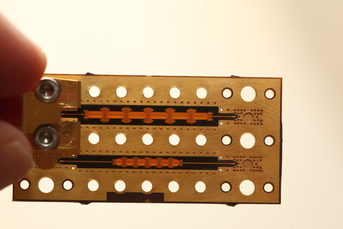
oh yeah, seconding the via question![]() @Bil Herd you might be interested in the RF filters that Darrell Harmon did on our Flex service https://twitter.com/HarmonInst/status/1102991659384528896
@Bil Herd you might be interested in the RF filters that Darrell Harmon did on our Flex service https://twitter.com/HarmonInst/status/1102991659384528896![]() @Aaron_Kraus Yep. The entire submission and design process is identical to normal rigid boards.
@Aaron_Kraus Yep. The entire submission and design process is identical to normal rigid boards.![]()
![]()
![]() @David Troetschel , wondering where you're going with this sounds cool.
@David Troetschel , wondering where you're going with this sounds cool.![]() O_o very nice
O_o very niceI guess you just answered all my questions for now
![]() @Aaron_Kraus Additionally, since the polyimide substrate is so uniform the interior plating tends to be very regular and smooth. Also, they're very short due to the thinness of the material, so a _little_ less resistance :)
@Aaron_Kraus Additionally, since the polyimide substrate is so uniform the interior plating tends to be very regular and smooth. Also, they're very short due to the thinness of the material, so a _little_ less resistance :)![]() @Drew Fustini That kind of stuff makes me grin maniacally.
@Drew Fustini That kind of stuff makes me grin maniacally.![]() is the a script available for generating spirals for inductors in kicad?
is the a script available for generating spirals for inductors in kicad?![]() As with any flexible design, ideally keep vias away from the portions of the board which you expect to be doing the maximum flexing.
As with any flexible design, ideally keep vias away from the portions of the board which you expect to be doing the maximum flexing.![]() is *there
is *there![]() you could create it in Inkscape, then use one of the KiCAD SVG importers
you could create it in Inkscape, then use one of the KiCAD SVG importers![]() @Michael Welling (good question)
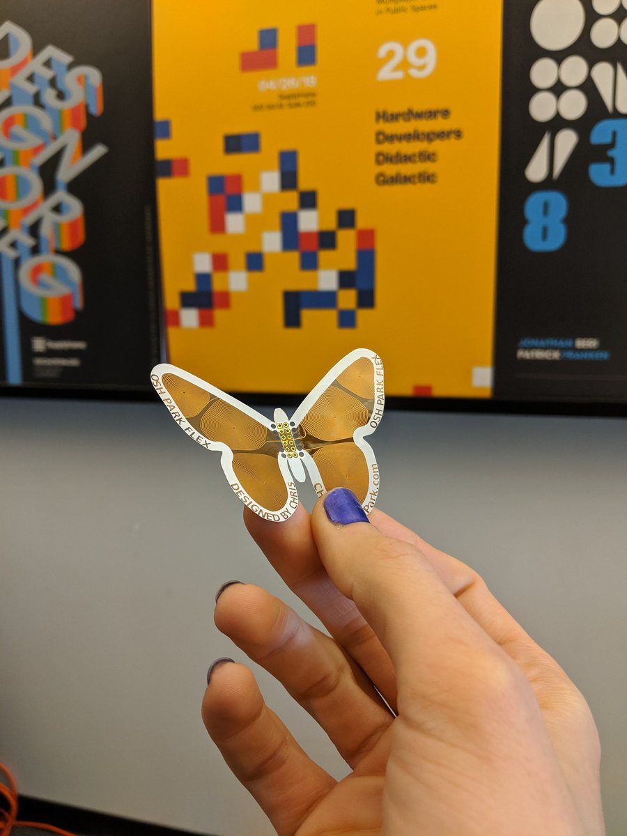
@Michael Welling (good question)![]() @Michael Welling I wrote one in Python for use on the butterfly and would like to try to adapt it to an Action script plugin soon.
@Michael Welling I wrote one in Python for use on the butterfly and would like to try to adapt it to an Action script plugin soon.![]() wondering if the process is documented some place?
wondering if the process is documented some place?![]() @oshpark I would love to see that code. Got it up somewhere?
@oshpark I would love to see that code. Got it up somewhere?![]() @oshpark hmm on a *more or less* sphere the flexing should be uniform on the full pcb :p
@oshpark hmm on a *more or less* sphere the flexing should be uniform on the full pcb :pso i should spread the vias uniformly as well?
![]() @Daren Schwenke Not yet! But after this Hack Chat I'll have motivation to do that sooner than later. :)
@Daren Schwenke Not yet! But after this Hack Chat I'll have motivation to do that sooner than later. :)![]() Any plans for 4-layer flex service?
Any plans for 4-layer flex service?![]() (could use right now)
(could use right now)![]() Oooo great question...
Oooo great question...![]() General cost for 2 layer flex sq inch?
General cost for 2 layer flex sq inch?![]() @Aaron_Kraus Generally, you only need to care about vias around _sharp_ bends. If it's a gradual, gentle bend, there's not as much concern. There's a lot of really good whitepapers to cover various aspects of mechanical design.
@Aaron_Kraus Generally, you only need to care about vias around _sharp_ bends. If it's a gradual, gentle bend, there's not as much concern. There's a lot of really good whitepapers to cover various aspects of mechanical design.![]() I don't think so right now. We are looking to increase volume on the 2 layer flex to increase the speed that we fill the panel.
I don't think so right now. We are looking to increase volume on the 2 layer flex to increase the speed that we fill the panel.![]() @Bil Herd Right now it's $10/square-inch of design, and for that you get the usual 3 copies shipped for free anywhere.
@Bil Herd Right now it's $10/square-inch of design, and for that you get the usual 3 copies shipped for free anywhere.![]() @Kris Winer No plans yet, but it's possible. Just as likely is the possibility we do 4 layer rigid flex, with 2 layers of flex sandwiched in 2 layers of rigid.
@Kris Winer No plans yet, but it's possible. Just as likely is the possibility we do 4 layer rigid flex, with 2 layers of flex sandwiched in 2 layers of rigid.![]() @Michael Welling this should work: https://github.com/mtl/svg2mod
@Michael Welling this should work: https://github.com/mtl/svg2mod![]() Goal would be weight reduction for flight controllers and animal trackers...
Goal would be weight reduction for flight controllers and animal trackers...![]() ? @Dan Sheadel , what would be the point?
? @Dan Sheadel , what would be the point?![]() @Kris Winer Yeah!
@Kris Winer Yeah!![]() I'm iiiiin! https://hackaday.io/project/165714-sprite-wand
I'm iiiiin! https://hackaday.io/project/165714-sprite-wand![]() Do you use the same fab house for flex as you do for rigid ? (Memory is it was GoldPhoenix)
Do you use the same fab house for flex as you do for rigid ? (Memory is it was GoldPhoenix)![]() Are there any free or affordable tools that can help with "3D" or foldable designs?
Are there any free or affordable tools that can help with "3D" or foldable designs?![]() All services are manufactured in the USA including the Flex
All services are manufactured in the USA including the Flex![]() Altium... oh wait, you said affordable.
Altium... oh wait, you said affordable.![]() @Bil Herd We don't actually use GoldPhoenix, but yeah, the fab that makes our flex also makes some of our rigid boards.
@Bil Herd We don't actually use GoldPhoenix, but yeah, the fab that makes our flex also makes some of our rigid boards.![]() @Nicolas Tremblay lets just say I have a pretty bored cat....
@Nicolas Tremblay lets just say I have a pretty bored cat....![]() thanks @Frank Buss
thanks @Frank Buss![]() Lol.. I will avoid saying that then. :)
Lol.. I will avoid saying that then. :)![]() @NikiSchlifke like Pepakura Designer?
@NikiSchlifke like Pepakura Designer?![]() how is the production process works? Premade Kapton sheets with a layer of copper on top? and than laminate another kapton layer as soldermask?
how is the production process works? Premade Kapton sheets with a layer of copper on top? and than laminate another kapton layer as soldermask?![]() Gold Phoenix was used by BatchPCB which OSH Park took over several years ago from SparkFun. All OSH Park orders are always fab'd in the U.S.
Gold Phoenix was used by BatchPCB which OSH Park took over several years ago from SparkFun. All OSH Park orders are always fab'd in the U.S.![]() @Nicolas Tremblay Rigid flex is super cool, in that you can have the benefits of both. Solid, fixed assembly points, and built in bendy wiring. You can basically fab a whole network of PCBs at once.
@Nicolas Tremblay Rigid flex is super cool, in that you can have the benefits of both. Solid, fixed assembly points, and built in bendy wiring. You can basically fab a whole network of PCBs at once.![]() @NikiSchlifke I really like FreeCAD, didn't try it in combination with KiCAD so far, but looks like it is possible:
@NikiSchlifke I really like FreeCAD, didn't try it in combination with KiCAD so far, but looks like it is possible:http://kicad-pcb.org/external-tools/stepup/
![]() Advanced?
Advanced?![]() That would explain the parity errors on the memory, thanks.
That would explain the parity errors on the memory, thanks.![]() @Maave yes!
@Maave yes!Well could you incorporate that into a pcb design workflow?
![]() What kind of weight reduction could be achieved with rigid flex vs regular 4-layer rigid pcbs? 20%? 50%?
What kind of weight reduction could be achieved with rigid flex vs regular 4-layer rigid pcbs? 20%? 50%?![]() @Dan Sheadel Now I get it. My mind is getting more blown minute by minute
@Dan Sheadel Now I get it. My mind is getting more blown minute by minute![]() I have no clue about using Pepakura with PCBs, I've only seen it used for craft projects
I have no clue about using Pepakura with PCBs, I've only seen it used for craft projects![]() @Kris Winer We'll get back on that one. We should be able to get Laen to weigh some QC boards to get a proper weight ratio.
@Kris Winer We'll get back on that one. We should be able to get Laen to weigh some QC boards to get a proper weight ratio.![]() @Aaron_Kraus it uses premade sheets of the polymide substrate with copper already applied. the soldermask is applied later with LPI process.
@Aaron_Kraus it uses premade sheets of the polymide substrate with copper already applied. the soldermask is applied later with LPI process.![]() @Maave I guess you could make the outline with it and use dxf/svg import to kicad
@Maave I guess you could make the outline with it and use dxf/svg import to kicad![]() Pepakura looks really perfect for doing flex designs. You'd certainly need to export and import it to generate gerbers for our process though.
Pepakura looks really perfect for doing flex designs. You'd certainly need to export and import it to generate gerbers for our process though.![]() @Dan Sheadel Pepakura dragon with LED eyes and ... touch sensors to change eye colours?
@Dan Sheadel Pepakura dragon with LED eyes and ... touch sensors to change eye colours?![]() and copper scales
and copper scales![]() Yeah Pepakura it is then :)
Yeah Pepakura it is then :)![]() and nichrome artificial muscles
and nichrome artificial muscles![]() @Maave jup just what i thought about
@Maave jup just what i thought aboutflappy winged dragon XD
![]() :) Friendly reminder that there's always room in the Hackaday flex contest for a friendly flexy dragon.
:) Friendly reminder that there's always room in the Hackaday flex contest for a friendly flexy dragon.![]() naw, coils and magnets..
naw, coils and magnets..![]() There is still time to submit to the contest and there is good chance that all entries will get free 2 square inches on our flex service:
There is still time to submit to the contest and there is good chance that all entries will get free 2 square inches on our flex service:https://hackaday.io/contest/163267-flexible-pcb-concept-contest
![]() @Dan Sheadel damn ... if I only had any spare time, apart from my other 500 side projects U_u
@Dan Sheadel damn ... if I only had any spare time, apart from my other 500 side projects U_uI'll see what I'm able to whipout in a short turn :)
Whats the deadline again?
![]() Since flex is laser-cut, the outlines can be more detailed than are normally achievable with a rotary milling bit used on rigid services.
Since flex is laser-cut, the outlines can be more detailed than are normally achievable with a rotary milling bit used on rigid services.![]() deadline is wednesday!
deadline is wednesday!![]() the contest ends May 29th (next Wednesday)
the contest ends May 29th (next Wednesday)![]() You just need to submit a project idea. Not a finished project
You just need to submit a project idea. Not a finished project![]() @NikiSchlifke Fusion360 has sheet metal mode, whereas you can create and work on any surface folded or unfolded. Also integrates with Eagle PCB, also free for non-comercial use.
@NikiSchlifke Fusion360 has sheet metal mode, whereas you can create and work on any surface folded or unfolded. Also integrates with Eagle PCB, also free for non-comercial use.![]() this project used paper to prototype the design:
this project used paper to prototype the design:https://hackaday.io/project/165256-fitm-flex-in-the-middle-for-power-analysis
![]() Will submit! @drew
Will submit! @drew![]() @oshpark Seriously? you lasercut that after everything is done? How awesome is that?
@oshpark Seriously? you lasercut that after everything is done? How awesome is that?![]() I can't wait until HaD has a 1 Cubic Inch contest for flex PCB
I can't wait until HaD has a 1 Cubic Inch contest for flex PCB![]() gerat!
gerat!![]() @Aaron_Kraus - remember, all the contest needs is an idea with some kind of documentation. Scribble a design down on a napkin even
@Aaron_Kraus - remember, all the contest needs is an idea with some kind of documentation. Scribble a design down on a napkin even![]() Will submit @Drew Fustini
Will submit @Drew Fustini![]() @Joe Miller nice thanks, I'm using Fusion 360 so I'll check that out
@Joe Miller nice thanks, I'm using Fusion 360 so I'll check that out![]() 1 'cubic' inch, aka, 20 bends of flex and components over an inch. :)
1 'cubic' inch, aka, 20 bends of flex and components over an inch. :)![]() @Joe Miller Wow, I haven't realized that, fusion360 really has everything I should have guessed.
@Joe Miller Wow, I haven't realized that, fusion360 really has everything I should have guessed.![]() Flex is a LOT of fun! The contest is a great way to jump in and get your feet wet, and see first hand some of the wild and cool things that can be done with it.
Flex is a LOT of fun! The contest is a great way to jump in and get your feet wet, and see first hand some of the wild and cool things that can be done with it.![]() Here is an interesting entry:
Here is an interesting entry:Möbius Flex https://hackaday.io/project/164528-mbius-flex
![]()
https://cdn.hackaday.io/images/145481554823951668.jpg
![]() neat! I was also thinkign of adding a modius
neat! I was also thinkign of adding a modius![]() hmmmm .. any good wearable examples?
hmmmm .. any good wearable examples?![]() Sheet metal tools are really nice, since you can actually specify bend radii. It's really handy when you have to get the lengths done properly. Actually sticking to the bend you design is a different matter entirely.
Sheet metal tools are really nice, since you can actually specify bend radii. It's really handy when you have to get the lengths done properly. Actually sticking to the bend you design is a different matter entirely.![]() So flex is really only 2D then....
So flex is really only 2D then....![]() 2D in 3D space
2D in 3D space![]() 2.5D
2.5D![]() i get that right?
i get that right?2 inches sqare, would be a square just shy of 36mm edge length?
![]() Ah, a projection.
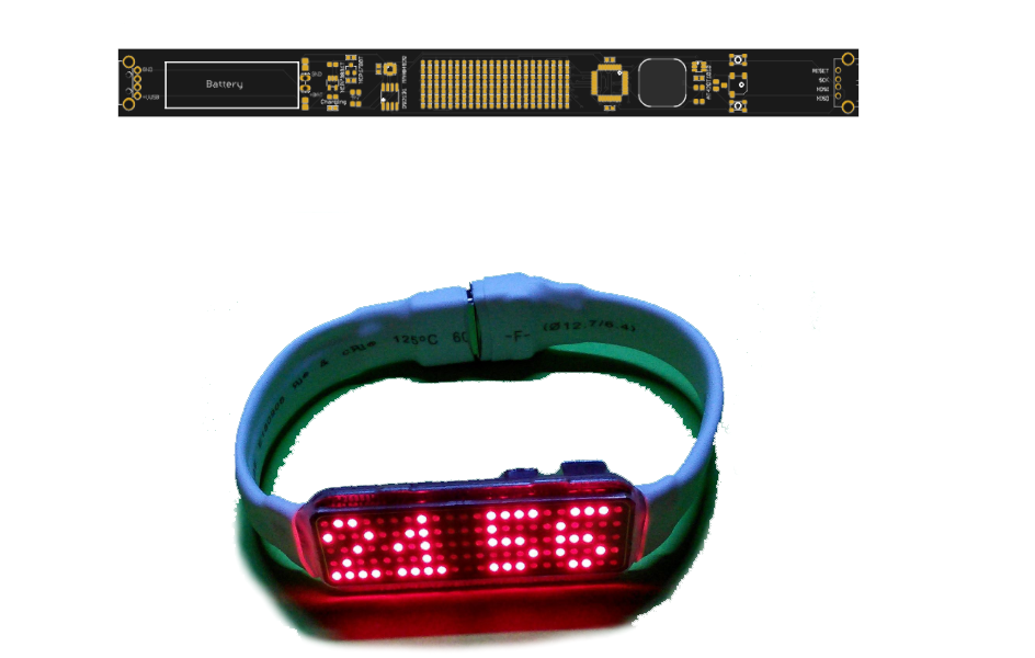
Ah, a projection.![]() @Michael Welling here is a wearable idea https://hackaday.io/project/164262-flexible-diy-nike-fuelband
@Michael Welling here is a wearable idea https://hackaday.io/project/164262-flexible-diy-nike-fuelband![]()
https://cdn.hackaday.io/images/9524541551948750100.png
![]() thanks Dan
thanks Dan![]() and the ultimate wearable:
and the ultimate wearable:Cyborg Eyeball Project https://hackaday.io/project/164544-cyborg-eyeball-project
![]() cool, bobricius is quite industrious
cool, bobricius is quite industrious![]() though not sure if that is a good idea :)
though not sure if that is a good idea :)![]() @Aaron_Kraus Correct.
@Aaron_Kraus Correct.![]() yikes!
yikes!![]() interesting wearable concept to detect sign language
interesting wearable concept to detect sign language https://hackaday.io/project/165673-flex-type-and-sign
![]() The 2 square inches of design space can be used as a 1" x 2", or an ~36 mm square, etc.
The 2 square inches of design space can be used as a 1" x 2", or an ~36 mm square, etc.![]()
Hack Chat Transcript, Part 1
05/23/2019 at 20:03 • 0 commentswhen's the hackchat? Don't want to miss it =(
![]() 1h?
1h?![]() in 50 minutes :)
in 50 minutes :)![]() 26 minutes now. Hack Chat coming up with Drew and Chris from OSH Park!
26 minutes now. Hack Chat coming up with Drew and Chris from OSH Park!![]() Yes!
Yes!![]() We are excited to talk about the Flex PCB contest and our Flex PCB service
We are excited to talk about the Flex PCB contest and our Flex PCB service![]() 60 winners, but only 49 contestants so far, sounds like it is not very difficult to win :-)
60 winners, but only 49 contestants so far, sounds like it is not very difficult to win :-)![]() Oh man, I should hurry up an make something then.
Oh man, I should hurry up an make something then.![]() flex PCB Cthulhu
flex PCB Cthulhu![]() hi
hi![]() soon to be 50 contestants
soon to be 50 contestants![]() @Alex Klimaj - You don't even have to make anything! Just an idea will do.
@Alex Klimaj - You don't even have to make anything! Just an idea will do.![]() that's what i did, just an idea
that's what i did, just an idea![]() unfortunately i did not expand upon it or implement anything
unfortunately i did not expand upon it or implement anything![]() i'd have to make a text to gerber converter somehow, possibly Eagle
i'd have to make a text to gerber converter somehow, possibly Eagle![]() don't want to get too creative at $10/square inch
don't want to get too creative at $10/square inch![]() I've been rush learning KiCad for this contest
I've been rush learning KiCad for this contest![]() that's not overly expensive for the application
that's not overly expensive for the application![]() even one page could hold a few favorite verses of the bible
even one page could hold a few favorite verses of the bible![]() ?
?![]() wouldn't that combust in contact with with the chemicals used for etching?
wouldn't that combust in contact with with the chemicals used for etching?![]() :)
:)![]() My idea was to print some the bible in kapton. lol that could be an issue
My idea was to print some the bible in kapton. lol that could be an issue![]() why waste good kapton?
why waste good kapton?![]() utilize the flex PCB to make a scroll
utilize the flex PCB to make a scroll![]() maybe that's the thing to do: if (detect == satanism) self(destruct);
maybe that's the thing to do: if (detect == satanism) self(destruct);![]() lol I could see making a microTorah out of flex...
lol I could see making a microTorah out of flex...![]() OMG a scroll, not a book! very cool!
OMG a scroll, not a book! very cool!![]()
![]()
![]() Hello from Supplyframe SF :)
Hello from Supplyframe SF :)![]() does it fly?
does it fly?![]() flex PCB glider would be sick
flex PCB glider would be sick![]() It can move :) Flying may take just a little longer ;)
It can move :) Flying may take just a little longer ;)![]() are we limited to kapton? are there other materials? I was thinking polyester?
are we limited to kapton? are there other materials? I was thinking polyester?![]() pretty sure there is only one substrate
pretty sure there is only one substrate![]() hmmm, origami in flex with creases where fill is not...
hmmm, origami in flex with creases where fill is not...![]() @oshpark just got a really nice pcb for my Unisolder from you ;)
@oshpark just got a really nice pcb for my Unisolder from you ;)![]() OK, it's noon here in UTC-7, so let's kick it off!. We're pleased to welcome Drew and Chris from OSH Park to the Hack Chat today, to discuss the details on flexible PCBs.
OK, it's noon here in UTC-7, so let's kick it off!. We're pleased to welcome Drew and Chris from OSH Park to the Hack Chat today, to discuss the details on flexible PCBs. Drew, can you kick us off?
![]() Ha, you made a butterfly... :)
Ha, you made a butterfly... :)![]() Hi Dan
Hi Dan![]() Hey Bil!
Hey Bil!![]() !
!![]() OSHPark rocks.
OSHPark rocks.![]() Thanks @Dan Maloney . At OSH Park, we are very excited about the Flex PCB contest currently on Hackaday
Thanks @Dan Maloney . At OSH Park, we are very excited about the Flex PCB contest currently on Hackaday![]() Great to see everyone today for Flex! Chris here.
Great to see everyone today for Flex! Chris here.![]() Chris is joining us as OSH Park
Chris is joining us as OSH Park![]() Hi Chris
Hi Chris![]() We hope everyone will checkout the Flex PCB contest:
We hope everyone will checkout the Flex PCB contest:![]()
https://hackaday.io/contest/163267-flexible-pcb-concept-contest
Flexible PCB Concept Contest
Flex your circuit's power!
![]() Hey Chris and Drew.
Hey Chris and Drew.![]() Hi
Hi![]() It ends next week so there is still time to enter
It ends next week so there is still time to enter![]() Digi-Key has partnered with Hackaday to provide the opportunity for 60 contest winners to receive 3 flexible circuits of their design! We will have 60 flexible designs (within 2 square inches or 13 square centimeters), manufactured with help from @oshpark and shipped directly to the winners!
Digi-Key has partnered with Hackaday to provide the opportunity for 60 contest winners to receive 3 flexible circuits of their design! We will have 60 flexible designs (within 2 square inches or 13 square centimeters), manufactured with help from @oshpark and shipped directly to the winners!![]() Hi @Dan Maloney @Bil Herd and @Alex!
Hi @Dan Maloney @Bil Herd and @Alex!![]() A friend wants to make a sphere out of flex pcb ~25-30cm so 9 3/4-11 3/4"
A friend wants to make a sphere out of flex pcb ~25-30cm so 9 3/4-11 3/4"how far can that stuff flex in 3D?
![]() We launched our 2 Layer Flex service at the beginning of the year. Here are details:
We launched our 2 Layer Flex service at the beginning of the year. Here are details:https://docs.oshpark.com/services/flex/\
![]() oops: https://docs.oshpark.com/services/flex/
oops: https://docs.oshpark.com/services/flex/![]() @Aaron_Kraus The Panasonic Felios substrtae we use is very flexible but also has good spring-back which should help it keep a more-rounded shape for an object that size.
@Aaron_Kraus The Panasonic Felios substrtae we use is very flexible but also has good spring-back which should help it keep a more-rounded shape for an object that size.![]() @Aaron_Kraus It'll flex all the way, so this is totally doable. It doesn't stretch though, so it'd have tessellation effects. Like a beach ball, soccer ball, or volleyball.
@Aaron_Kraus It'll flex all the way, so this is totally doable. It doesn't stretch though, so it'd have tessellation effects. Like a beach ball, soccer ball, or volleyball.![]() is it possible to solder flex PCB in a reflow oven? what are the temperature specs?
is it possible to solder flex PCB in a reflow oven? what are the temperature specs?![]() Increased use of copper will cause the flex to become more ductile and retain it's shape. That's something you might want to avoid on flex cables where you want more spring, but for a sphere it might also help keep the final shape better.
Increased use of copper will cause the flex to become more ductile and retain it's shape. That's something you might want to avoid on flex cables where you want more spring, but for a sphere it might also help keep the final shape better.![]() @Frank Buss Absolutely! Our Flexible PCBs have the highest temperature ratings of any of our services, and can handle lead-free reflow with no problem.
@Frank Buss Absolutely! Our Flexible PCBs have the highest temperature ratings of any of our services, and can handle lead-free reflow with no problem.![]() cool
cool![]() what's the operating temperature limit?
what's the operating temperature limit?![]() can we crease the PCB?
can we crease the PCB?![]() How about regular iron soldering and soldering egde to egde?
How about regular iron soldering and soldering egde to egde?![]() @Les Hall sounds breaky. The oshpark specs page has a recommended bend radius
@Les Hall sounds breaky. The oshpark specs page has a recommended bend radius![]() Panasonic specs 288ºC for 1 min soldering for our R-F775. The full data sheet can be found here https://docs.oshpark.com/resources/flex-panasonic-felios-F775.pdf
Panasonic specs 288ºC for 1 min soldering for our R-F775. The full data sheet can be found here https://docs.oshpark.com/resources/flex-panasonic-felios-F775.pdf![]() @Les Hall Yeah. We have a relatively springy substrate, but it'll still hold a shape if you bend it sharply. If you have copper in a bend, it'll hold shape better, but you can't bend it quite as sharply and expect the signal to hold together. It's a pretty tight bend radius.
@Les Hall Yeah. We have a relatively springy substrate, but it'll still hold a shape if you bend it sharply. If you have copper in a bend, it'll hold shape better, but you can't bend it quite as sharply and expect the signal to hold together. It's a pretty tight bend radius.![]() Do you have specs on website for the flex such as Dk, Df , and whether Tg applies like in epoxy-glass PCBs?
Do you have specs on website for the flex such as Dk, Df , and whether Tg applies like in epoxy-glass PCBs?![]() @Nicolas Tremblay Yep. Both of those are OK. You can get copper pretty close to the edge, so you can use exposed pads to weld two pieces together.
@Nicolas Tremblay Yep. Both of those are OK. You can get copper pretty close to the edge, so you can use exposed pads to weld two pieces together.![]() @oshpark @Dan Sheadel So More Copper gets me a "Less Flexible, more robust" structure?
@oshpark @Dan Sheadel So More Copper gets me a "Less Flexible, more robust" structure?how is this effecting bigger structures like the 10" sphere? Any guesses how many sections i need to get a halfway decent ball?
And Edge soldering would be quite interesting
![]() There is great information about the RF characteristics of OSH Park 2 layer flex in this KiCon talk"
There is great information about the RF characteristics of OSH Park 2 layer flex in this KiCon talk""Microwave Design with KiCad" - Darrell Harmon (KiCon 2019)
![]() ty @Dan Sheadel was wondering about making a scroll as someone else here suggested, thinking ahead of a crease in each end or not.
ty @Dan Sheadel was wondering about making a scroll as someone else here suggested, thinking ahead of a crease in each end or not.![]() @Aaron_Kraus Exactly. Flooding both sides with a copper fill would make the board malleable and hold it's shape reasonably well after bending.
@Aaron_Kraus Exactly. Flooding both sides with a copper fill would make the board malleable and hold it's shape reasonably well after bending.![]() The copper is annealed and soft, which is specific and necessary to flexible circuits.
The copper is annealed and soft, which is specific and necessary to flexible circuits.![]() @Aaron_Kraus Basically. It's actually a bit stiff when you have a copper plane or two, and really bendy with no copper. Most boards will be in the middle. Hatched copper pours are really great to get a fairly consistent bend across the board.
@Aaron_Kraus Basically. It's actually a bit stiff when you have a copper plane or two, and really bendy with no copper. Most boards will be in the middle. Hatched copper pours are really great to get a fairly consistent bend across the board.![]() Thanks. Your standard Isola FR-408 rocks, I was going to mention that in my next vid.
Thanks. Your standard Isola FR-408 rocks, I was going to mention that in my next vid.![]() @Bil Herd Harmon Instruments has some measurements here: https://twitter.com/HarmonInst/status/1084142351210037249
@Bil Herd Harmon Instruments has some measurements here: https://twitter.com/HarmonInst/status/1084142351210037249![]() To add to the barrage of questions; I get that this is a polymide film, has anyone (ultrasonically) welded it together?
To add to the barrage of questions; I get that this is a polymide film, has anyone (ultrasonically) welded it together?![]() Thanks @Drew Fustini
Thanks @Drew Fustini![]() There is more information in the datasheet for our flex https://docs.oshpark.com/resources/flex-panasonic-felios-F775.pdf
There is more information in the datasheet for our flex https://docs.oshpark.com/resources/flex-panasonic-felios-F775.pdf![]() Ah, thats what I was looking for, thanks!
Ah, thats what I was looking for, thanks!![]() @David Troetschel that is an interesting idea, but I don't believe we have seen anyone try that yet
@David Troetschel that is an interesting idea, but I don't believe we have seen anyone try that yet![]() @Les Hall If you make this let us know! That sounds awesome. I think any anchoring method at the ends will be fine if you're not passing active circuitry between the roll and the "paper". If you are, perhaps consider a wire-specific region in the middle that has more room to "bend" rather than crease.
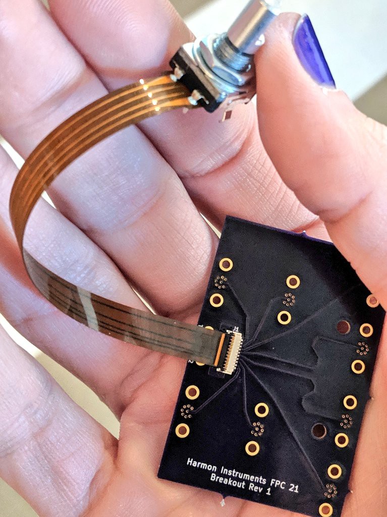
@Les Hall If you make this let us know! That sounds awesome. I think any anchoring method at the ends will be fine if you're not passing active circuitry between the roll and the "paper". If you are, perhaps consider a wire-specific region in the middle that has more room to "bend" rather than crease.![]() For those interested in connectors, Harmon Instruments found a connector on Digi-Key that works well:
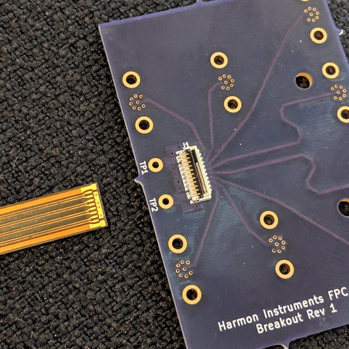
For those interested in connectors, Harmon Instruments found a connector on Digi-Key that works well:https://twitter.com/HarmonInst/status/1095448040243003392
![]()
![]()
![]()
![]()
![]() @Drew Fustini I happen to have access to a machine...
@Drew Fustini I happen to have access to a machine...![]() very interesting... we would love to hear the results
very interesting... we would love to hear the results![]() @Bil Herd The Dk on Panasonic's Felios substrate is nominally 3.2 which also makes it an excellent candidate for RF work. In fact our current stack-up was partly chosen to enable making common impedances relatively easy. https://docs.oshpark.com/services/flex/
@Bil Herd The Dk on Panasonic's Felios substrate is nominally 3.2 which also makes it an excellent candidate for RF work. In fact our current stack-up was partly chosen to enable making common impedances relatively easy. https://docs.oshpark.com/services/flex/![]() @Drew Fustini and those connectors are without backing on the flex?
@Drew Fustini and those connectors are without backing on the flex?![]() I'm assuming this is almost identical to Kaptan? I think I have some lying around. I'll give it a shot next time I'm around the machine.
I'm assuming this is almost identical to Kaptan? I think I have some lying around. I'll give it a shot next time I'm around the machine.![]() Please submit an idea to the Flex PCB contest. You should be able to get a gift code given the current number of entries
Please submit an idea to the Flex PCB contest. You should be able to get a gift code given the current number of entries![]() DK part: https://www.digikey.com/product-detail/en/te-connectivity-amp-connectors/2-2328724-1/A141393CT-ND/9565592
DK part: https://www.digikey.com/product-detail/en/te-connectivity-amp-connectors/2-2328724-1/A141393CT-ND/9565592![]() @David Troetschel Correct! It's basically the same as DuPont Pyralux, etc.
@David Troetschel Correct! It's basically the same as DuPont Pyralux, etc.![]() @morgan the flex has no stiffner but is rigid enough to insert into the connector
@morgan the flex has no stiffner but is rigid enough to insert into the connector![]() cool
cool![]() how concistent is the thickness (variation) of the flex PCB over a bigger area?
how concistent is the thickness (variation) of the flex PCB over a bigger area?![]() nice, that connector is cheaper than what I was looking at
nice, that connector is cheaper than what I was looking at![]() Also has Tan loss of .002 at 1Mhz looks like which is the other factor dragging on high speed.
Also has Tan loss of .002 at 1Mhz looks like which is the other factor dragging on high speed.![]() @morgan You can adjust the thickness somewhat by choosing which layers to use at the connector, such as adding copper or not on the bottom, etc.
@morgan You can adjust the thickness somewhat by choosing which layers to use at the connector, such as adding copper or not on the bottom, etc.![]() @Aaron_Kraus The substrate thickness spec is +/- 0.4mil . That's over on our flex specs if you need it later.
@Aaron_Kraus The substrate thickness spec is +/- 0.4mil . That's over on our flex specs if you need it later.![]() Recently found some HP 5082-7415 5x7segment led modules from over 40 years ago. Anyone still having some around or ideas what to do with it? They got pretty rare.
Recently found some HP 5082-7415 5x7segment led modules from over 40 years ago. Anyone still having some around or ideas what to do with it? They got pretty rare.Sadly half of them have damaged segments. Probably loose bondwires.
Made a simple interface board if you want to use them: https://hackaday.io/project/165710-hp-5082-74xx-7-segment-display-revived
Maybe a geiger counter, a watch or some other readout. :) I love the glow
 Lutetium

 We're getting up to the end of the hour, so I'm going to call official time and thank Drew and Chris for dropping by. They might need to get going, but feel free to hang around and answer questions if you like.


