Patrick Joyce
-
The force feedback is strong in this one...
10/02/2016 at 16:39 • 0 comments![]()
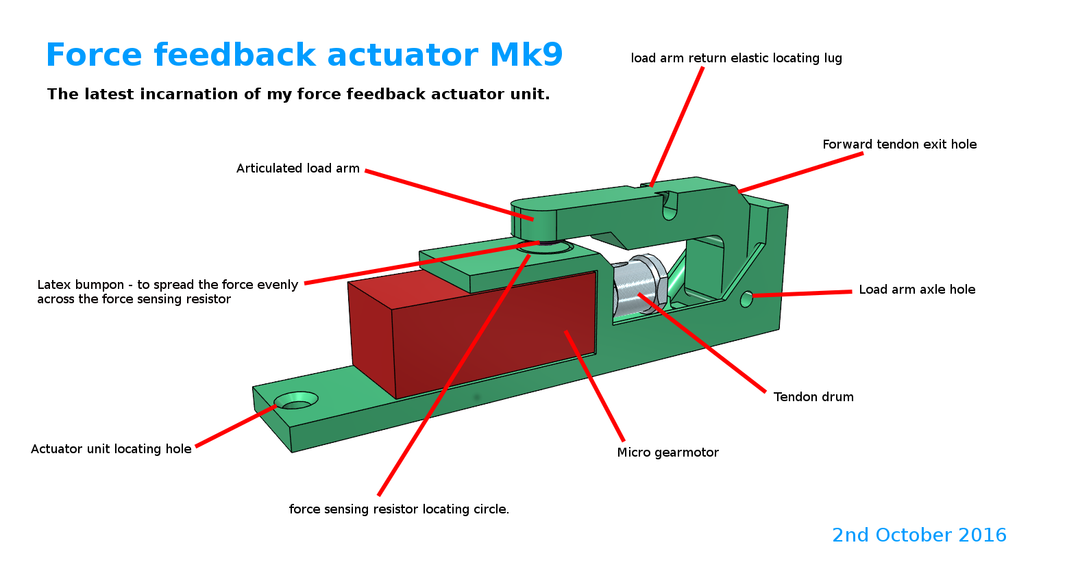
Since the last update I've been busy refining the design for the force feedback actuator, to increase its sensitivity range as much as possible (to enable a range of grip strengths). I also realised that it would be extremely helpful if it could sense when the tendon wire went slack. In normal operation this only happens when the fingers are opened out flat. Sensing when the fingers were flat would allow them to stop there, without any of the programming gymnastics the previous system would have required. The tendon wire going slack, could also occur in a situation when the closed fingers were physically prevented from opening for some reason. If this happened, then the danger is that the motor would unwind the tendon drum, despite there being no tension in the tendon wire. This would result in a tangled snarl of tendon wire inside the drum housing – potentially stopping it working entirely.
My early designs had the load arm able to move freely when the tendon wire lacked tension. This worked fine on the stationary test rig, but would have produced unpredictable results when the arm was used in practice (gravity coming from different directions as the arm was used). So I've added a load arm return spring in the latest design.
-
Last minute, total, change of direction!
09/07/2016 at 19:01 • 0 commentsExciting news! I've struggling for months with the design of the fingers on the bionic hand. I haven't been able to get the force needed to operate the finger low enough. I always intended to use tendons to actuate the fingers, and springs or elastic to return the fingers to a straight position. So the actuator has to pull against the return spring as well as the friction within the tendon mechanism. Try as I might, I couldn't get the no load pull weight down below four hundred grams. Very frustrating. It worked, but 400grams just seemed excessive. Then I found the TACT hand online, which uses a combination of tendons and rigid bars to actuate its fingers. It was an epiphany! So I set about designing my own combination actuated bionic finger. After six prototypes, we (I couldn't have done it without Toni, my carer) have got the no load pull weight down to 100 grams. This opened up the possibility of using nano servos as actuators, making each finger individually controllable. So i'm setting about redesigning the hand from scratch – with only four weeks to go before the hackaday prize deadline. Its possible. Just....
-
Soldering (again), fingers, and hubris....
08/26/2016 at 09:42 • 2 comments![]()
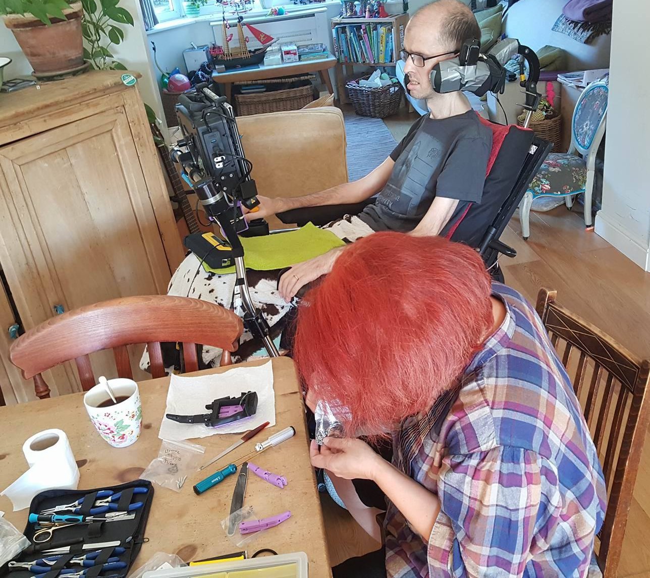
Toni (my carer) assembling the redesigned hand.
So, dad had soldered up the prototype forearm lid (containing all the control electronics for the hand). It worked a treat, once we'd re soldered one wire, that was in the wrong hole. Finally, I could dismantle the test rig, with all its unsightly Dupont cables.
On testing this beautiful new, self contained, bionic arm, one thing soon became apparent. There was still too much friction in the finger tendon design, and the new elastic finger return mechanism was in need of improvement. So, I dismantled the test rig, safe in the knowledge that I wouldn't need it again (oh, the hubris!), and cracked on with a ground up finger redesign. We finally finished printing and assembling the redesigned hand this morning. We bolted it to the forearm, and got ready to test. Plugged in the power pack, turned it on.... and.... nothing happened. Then, after a few seconds.... fizzle BANG!, followed by a little puff of blue smoke.
Oh dear. And just as i'd thought i'd finally seen a glimpse of the light at the end of the tunnel.
And unfortunately, my dad is in France until next week. So we're busy putting the test rig back together at the moment. Finding out what went wrong will have to wait for dad's return from holiday. I did a visual inspection, and can't see any burnt components, or obvious shorts.
My only theory is that the 5v pro micro I am using couldn't cope with the 12.5v that the power pack was delivering? - as its only supposed to run on a maximum of 12v.Do any of you lot have any opinions on whether this is likely or not?
-
Soldering, and the limitations of quadriplegia.
08/11/2016 at 19:25 • 0 comments![]()
Last Friday my Dad came over, to wire up the prototype arm. I'm a quadriplegic myself, and can't talk or use my hands, so I rely on carers, friends and family to build my projects. Unfortunately, my dad is the only one with good soldering skills, and he has limited time. He managed to get it all soldered up last week, but then he ran out of time, and we didn't get to test it before he had to leave. I tested it myself after he left. The screen worked on usb power, but nothing else did. My troubleshooting stopped there, as its a mess of tangled wires.
It has been very frustrating sitting here for a week, looking at it, knowing I could fix it in minutes, if only my hands still worked.
Dads back tomorrow, and we'll sort it then. But meanwhile, i've come up with a new wiring design for the second prototype, with headers on the pro micro. The new design should allow me to test, and troubleshoot each component individually.
In other news, I've had problems with my homemade torsion springs, getting the spring power right. They also increase the build complexity considerably, which isn't a good thing. So while I remake the springs, I am also testing a different design - with elastic cord as the finger return mechanism. More news on that in the next update.
-
Actuators and the Forearm!
08/02/2016 at 17:21 • 0 comments![]()
Things have been busy here at bionic arm HQ. I've been slack about doing updates, so there's lots to tell.
Firstly, I decided to sort out the actuators. My requirements are fourfold. They need to be strong, know when they have reached their limits, and be capable of sensing when force requires them to stop – some kind of force feedback. They also need to be really small, and easily available off the shelf.
The force feedback thing was the tricky one. This is necessary when you grip something large, and tell the hand to close around it. It physically can't close all the way - and without some kind of feedback, the actuator will keep trying to close, and potentially damage itself.
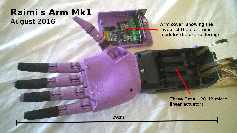
The micro servos I was using were not strong enough, and full size servos are too large to fit in a child's forearm. I explored miniature gearbox motors for a long time, eventually designing a prototype that 'might' have worked, but was fiendishly complex. In the end I reluctantly declared that a blind alley, and bought some Firgelli micro linear actuators. I was hoping to find a cheaper solution, as I want the arm to be cheap to build - three Firgelli actuators costing £180 in the UK. Now that I have them though - I love them! Small, powerful, and with an internal potentiometer, which I can use for limit switching, and a force feedback equivalent.
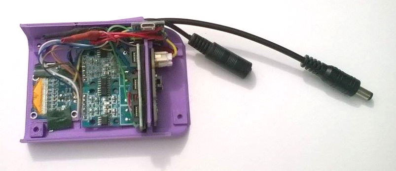
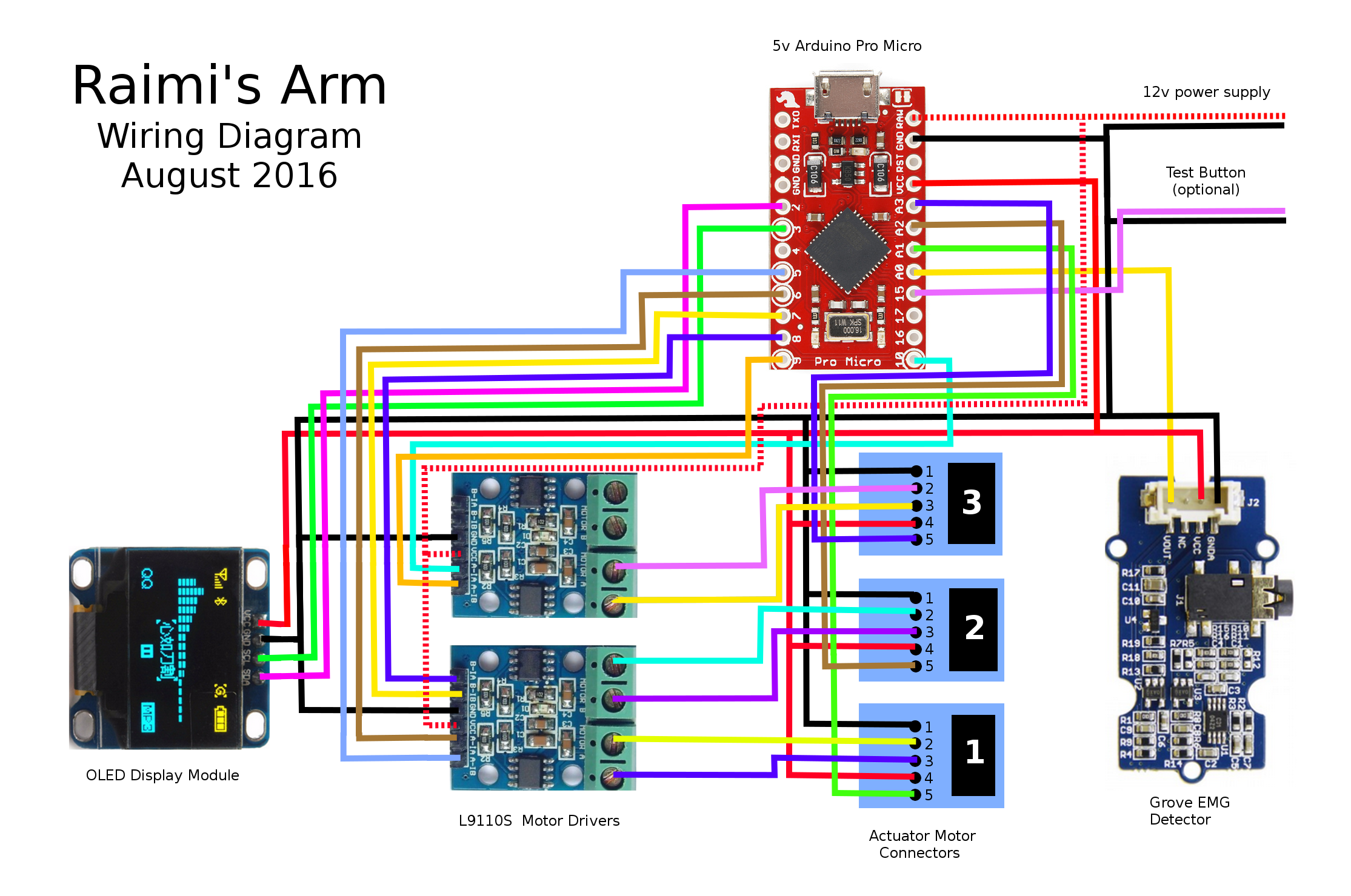
You'll see on the picture that I now have the forearm built as well. It was quite a challenge to squeeze all the electronics and three actuators into a tube twelve centimetres long. But I think I've succeeded. I'll know on Friday, when my dad comes to solder everything together. I had to ditch the rtc module, which was a shame, just not enough room. Wiring diagram below. The arm is powered by a rechargeable 12v power pack, which will live in a pocket, or on a belt.
You'll also notice that the fingertips are rubber coated for grip. After lots of experimentation I found that modelling balloons are the perfect size, and really grippy.
I've also built the rotating wrist mechanism, and made some nifty changes to the tendon system, but more about that in the next update....
![]()
-
Health and computer issues....
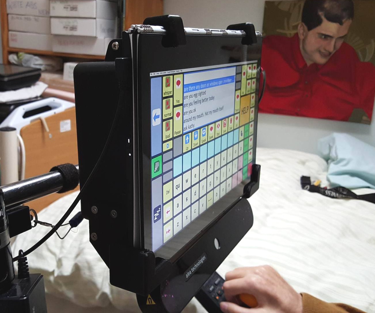
05/25/2016 at 11:21 • 0 commentsMy health has stabilised - luckily. But as soon asI was able to get back to work, my computer reached the limit of its capabilities. As the CAD models of the hand and forearm got more complex, the computer slowed and slowed, til it became unusable. And then, even worse, it died completely. So i needed a new, wheelchair mounted computer - fast. Unfortunately, i already had the most powerful commercially available wheelchair mounted computer, and that was not powerful enough. So i hacked my own!
![]()
I bought a high spec convertible laptop, and made a mounting box out of the bottom half of a waterproof suitcase. I 3d printed the mounting brackets for the front. Inside the case is the mounting bracket for the eyegaze unit, and amplification gear. On the back is a quick release plate, which locates on my existing mount arm. Eventually the backbox will contain all kinds of gadgets, but for the moment i'm concentrating on Raimi's arm again. I've had three very frustrating weeks - but now i'm back in the game!
-
Spring success, and impending dooom...
04/01/2016 at 11:19 • 1 commentSo. Progress is being made. Painfully slowly, but progress nonetheless. The internally sprung finger prototype is up and running, as you can see in the video. I'll make a whole hand next...
The reason for the slow progress is quite serious unfortunately. Recently the progression of my motor neuron disease has taken a turn for the worse. I can no longer swallow with my head upright. This means i'm having regular choking episodes, to avoid which, I need my head lowering down on to my chest. This process sucks the energy out of me. I'm only managing an hour or two's work each day, before becoming utterly exhausted. This raises the possibility that I won't finish this project before I die. I'm fighting hard, but MND/ALS is a relentless and unstoppable disease. Things are not looking rosy at the moment.
-
Spring!
03/21/2016 at 16:06 • 0 comments![]()
The three main issues i'm working on at the moment are: the wrist joint, the forearm layout, and the thumb. I realised last week, that I couldn't work on the hand in isolation anymore, I would have to design the forearm and hand together. I hadn't done this from the start, because my wheelchair mounted computer, while powerful for its type, is puny and inadequate for CAD work. Its all I have however, so i've made do. I'm designing the arm in small sections, that my computer can cope with.
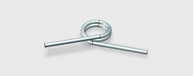
Raimi has a partial forearm, so the space between the tip of her forearm, and the base of the hand, is the space i'll have to fit three actuators and the wrist joint into. It is 12cm long. Which isn't very big. So to maximise the space in the forearm, i've decided that the finger return springs would be better off in either the palm, or the fingers themselves. After a lot of experimentation (with the help of my carers), I have arrived at an excellent solution. I'm going to make my own springs that fit inside each finger joint. I knocked together a rough, proof of concept, prototype, with the help of my dad. Since then i've redesigned the finger joint to suit. Made a jig for the springs, and ordered more spring steel wire.
The picture is a CAD model i've made to help explain to my carers, what I want them to make. I'll post a video when I get the first finger working – hopefully tomorrow....
Raimi's Arm - Bionic Arm for Kids
Open source, high functioning, myoelectric, bionic arm for kids.