Close
0%
0%

Model S BMS hacking

Reverse engineer, reprogram or otherwise use the UV/OV/balancing circuits built into each of the 16 modules in a Tesla Model S battery pack.

Similar projects worth following
Batteries from 85KWh Tesla Model S packs are now becoming available from wrecked cars, these are perfect for DIY EV builds or off-grid batteries and they even come with built in cell monitor and balancing circuits!
The 85KWh pack contains 16 modules, each of which is a 6s 74p array of 18650 cells, 96 series cells total. Each 6s module communicates with a master BMS via an isolation barrier, the master BMS talks to the ECU and charger and controls the main contactors.

The aim of this project is to design a board that can communicate with any number of modules, read out cell voltages, balancing status, control contactors and communicate with external charging/inverter electronics to protect the cells.

We now know the basic communication scheme used within the pack between each of the 16 modules! check out the project logs.

A basic Arduino Due based BMS controller is up on Collin's Github: (The BMS available from EVTV is based on this project.)

https://github.com/collin80/TeslaBMS

Another branch for the Teensy 3.2 by TomDeBree: (this one includes hardware design)

https://github.com/tomdebree/TeslaBMS

We are currently working on code required to preform basic cell voltage and temperature measurements, and implement a cell balancing scheme.

Other features will include:

- A charge controller to interface with an OEM charger via CAN bus.

- DC Contactor control circuitry including pre-charge capability.

- Current shunt for tracking state of charge (fuel gauge) and providing over current protection.

bms.bin

8051 Code dump from a GEN2 BMS module.

octet-stream - 15.00 kB - 01/14/2018 at 20:21

Download

code2.BIN

8051 code dump from another module

octet-stream - 7.36 kB - 02/27/2017 at 07:10

Download

wiring.pdf

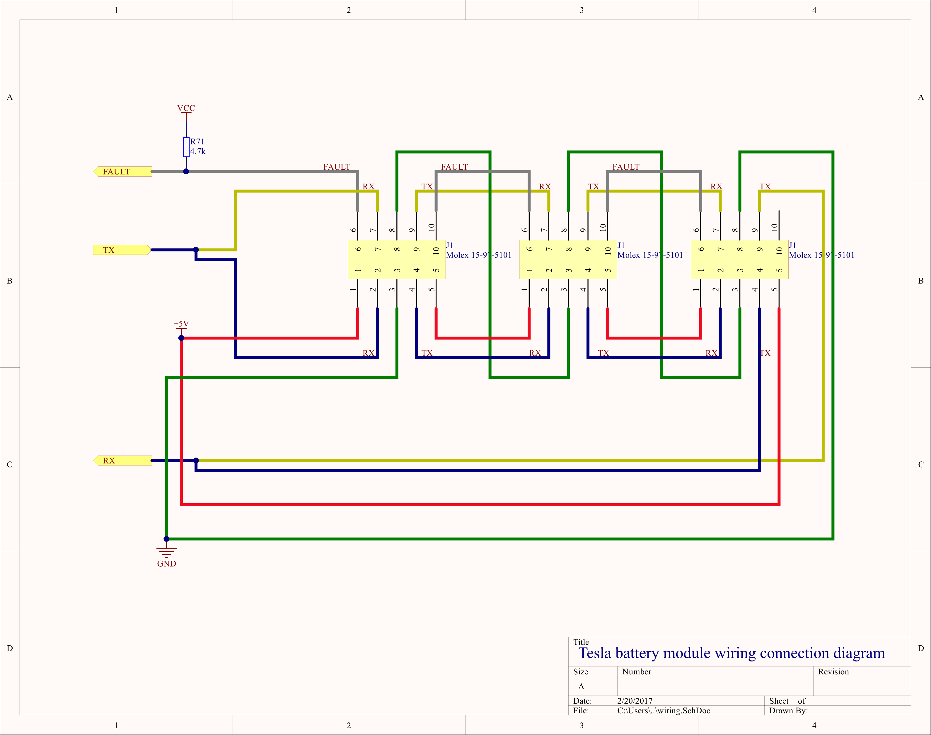
Example diagram showing wiring of the J1 connectors to the master BMS board.

Adobe Portable Document Format - 78.17 kB - 02/21/2017 at 06:47

Preview

partialTeslaBMS_Altium_02.pdf

Adobe Portable Document Format - 332.76 kB - 02/21/2017 at 06:20

Preview

TeslaBMS_02.py

V0.2

py - 4.37 kB - 02/20/2017 at 04:57

Download

View all 7 files

  • 1 × Module BMS connector Connector is Molex 15-97-5101, pins are 39-00-0038, retaining key is 15-97-9101. http://www.digikey.com/product-detail/en/molex-connector-corporation/15-97-5101/WM4772-ND/1624637
  • 1 × Arduino Due or Teensy 3.2 Both these microcontrollers will operate at the correct UART baud rate and have CAN controllers
  • 1 × MCP2561, MCP2562FD or other CAN transcever only required if interfacing with vehicle CAN bus.
  • 1 × Contactors For pack isolation during power down or fault conditions.
  • 1 × Pre-charge resistor To limit inrush current into DC link capacitance. This will be coupled with a small contactor

View all 6 components

  • Wiring modules together

    Jarrod03/02/2017 at 05:30 1 comment

    I spent some more time tracing out the logic between the RF isolator and microcontroller to try and determine the actual function of the 4th channel on the isolator and just how the power down circuits work.

    Ch4 does appear to be a fault line, it is connected, via a NAND gate to the FAULT_H pin on the BQ76 BMS IC, so this will drive the shared fault line (on pin 6 and 10 of the main connector) low in the case of an over temperature, over voltage or under voltage event. A diode is used to make it a dominant fault line, ie any fault on any module will force a fault state. This should work even if a module microcontroller stops responding (which would otherwise kill the daisychain UART communications.) Weirdly, the other pin of this NAND is derrived from a second NAND of the SDO pin and the RF com chip disable line. It's not clear to me what this achieves.

    I also found the main connector (J1) part number by sorting through digikey, It looked like a Molex, that and the pins + spacing was enough to go on. Connector is Molex 15-97-5101, pins are 39-00-0038, retaining key is 15-97-9101.

    So now it's pretty clear how the modules should be wired up to a controller. Here is an example for three modules (it can be extended to any number, up to 62 from what I can tell)

    All this wiring is isolated from the cells, so the gnd and +5V can safely be on the 12V wiring potential in an automotive application.

    A couple of the other team members, Collin and Tom are working on an Arduino sketch to interface with the serial protocol based on my earlier findings, this should now be ready to test out and get basic functionallity like voltage and current readings. https://github.com/collin80/TeslaBMS

    Or if you have python and an FTDI board and just want to mess around, try the python script in the files section of this hackaday.io project.

  • bms settings

    Jarrod02/16/2017 at 08:41 2 comments

    One of the reasons I wanted to reverse engineer rather than replace the microcontroller on the module BMS board is that Tesla have carefully selected voltage levels for under/over voltage thresholds and balancing levels. So it's a bit of a bummer to find that the modules themselves don't seem to have these values built in, it's handled higher up the control chain.

    But the BQ76 does have a hardware over and under voltage threshold, as well as over temperature built in, which pulls a shared fault line low.

    There are also some other configuration values worth reading out, and since I do have a bunch of boards which have had power applied since the last time they were used, since they have this huge battery backup - the hundreds of 18650 cells - to keep the RAM powered!

    So how do we read it out? need to find the address first, using my python script we can iterate through the possible addresses with something like

    for address in range(0x3E):
        sendData(Read,[address, 0x00, 0x4C])

    And eventually, at address=0x0F I get the result:

    TX: 0x1e, 0x0, 0x4c,

    RX: 0x1e, 0x00, 0x4c, 0x81, 0x2a, 0x25, 0x25, 0xa5, 0x25, 0xab, 0x25, 0xae, 0x25, 0xad, 0x25, 0xac, 0x25, 0xaa, 0x0a, 0x99, 0x0a, 0x93, 0x00, 0x00, 0x00, 0x00, 0x00, 0x00, 0x00, 0x00, 0x00, 0x00, 0x00, 0x00, 0x00, 0x00, 0x00, 0x00, 0x00, 0x00, 0x00, 0x00, 0x00, 0x00, 0x00, 0x00, 0x00, 0x00, 0x00, 0x00, 0x00, 0x3d, 0x03, 0x00, 0x00, 0x00, 0x00, 0x00, 0x00, 0x00, 0x00, 0x00, 0x8f, 0x00, 0x00, 0x00, 0x00, 0x10, 0x80, 0x31, 0x81, 0x08, 0x81, 0x66, 0xff, 0x15, 0x00, 0x00, 0x00, 0xad,

    Labeling each register:

    0: 81        #status register
    1: 2a 25     #GPAI measurement data
    3: 25 a5     #cell 1 voltage data
    5: 25 ab     #cell 2 voltage data
    7: 25 ae     #cell 3 voltage data
    9 25 ad      #cell 4 voltage data
    b: 25 ac     #cell 5 voltage data
    d: 25 aa     #cell 6 voltage data
    f: a 99      #TS1 voltage data
    11: a 93     #TS2 voltage data
    13-1f rsvd   
    20: 0        #alert status
    21: 0        #fault status
    22: 0        #OV fault state
    23: 0        #UV fault state
    24: 0        #parity result A
    25: 0        #parity result B
    26-2f rsvd
    30: 3d       #ADC measurement control
    31: 3        #I/O pin control
    32: 0        #cell balancing control
    33: 0        #cell balancing max on time
    34: 0        #ADC conversion start
    35-39: rsvd
    3a: 0        #group 3 registers write access control
    3b: 8f       #Address register
    3c: 0        #reset control
    3d: 0        #test mode selection
    3e: rsvd
    3f: 0        #EPROM programming enable
    40: 10       #Function configuration
    41: 80       #IO configuration
    42: 31       #OV setpoint
    43: 81       #OV time delay
    44: 8        #UV setpoint
    45: 81       #UV time delay
    46: 66       #over temperature set point
    47: ff       #over temperature time delay
    48: 15       #user data 1
    49: 0        #user data 2
    4a: 0        #user data 3
    4b: 0        #user data 4

    So the values after 0x3F are identical to those read from the EPROM on a restart, they set to OV/UV/OT and time delays.

    OV setpoint = 0x31, datasheet says 2V + 50mV * 49 = 4.45V

    UV setpoint = 0x08. datasheet says 0.7V + 100mV * 8 = 1.50V

    OT setpoint = 0x66. Table 2 says this corresponds to 1.578V, which is 65C for a 10k NTC such as ERT-J1VG103FA

    Interesting values, the cells will basically be on fire if they reach these voltages.. The temperature value is much more reasonable.

    Since we can't guarantee the register content, best practice is to just reset the BQ76 chips with a broadcast reset, then set it up from scratch. EPROM values will be loaded automatically but there are a few registers that require setup after a reset, Address control, ADC control, IO control and the fault and alert registers.

    ### ~~ Startup Code ~~ ###
    #A5 is the magic value to reset the chips
    sendData( Write, [broadcast, RESET_CONTROL, 0xA5])    
    #set address
    sendData( Write, [0x00, ADDRESS_CONTROL, address|0x80]) #do this for each BMS on the daisychain
    #configure ADC
    sendData( Write, [address, ADC_CONTROL, 0x3D])
    #configure IO
    sendData( Write, [address, IO_CONRTOL, 0x03])
    #clear faults, need to write a 1 to the fault bit to be cleared, then a zero
    sendData( Write, [address, ALERT_STATUS, 0x80])
    sendData( Write, [address, ALERT_STATUS, 0x00])
    sendData( Write, [address, FAULT_STATUS, 0x08])
    sendData( Write,...
    Read more »

  • UART protocol cracked!

    Jarrod02/15/2017 at 03:44 7 comments

    As I found in the last post, the isolated UART bus daisychained through the Tesla modules is running at an odd frequency, 612,500bps. This is problematic as it is not a standard PC baud rate. I had an FTDI board lying around so I had a peek at the datasheet to discover it has a highly configurable baud rate generator, easily configured to within 3% of 612kbps. In addition, the windows driver handles configuration automatically.

    To test this out I wrote a python script, PySerial was fine with the non standard rate, and the frequency was confirmed with a logic analyser.

    One of my collaborators, Tom has been probing out a module BMS hooked up to a master board, he found that a serial string is periodically transmitted and this results in SPI bus activity, just the status register being read. However, we had issues decoding the exact UART messages as he was lacking decent analysis tools. I Figured I would try repeating the test by sending the supposed data with my FTDI board anyway.

    All I observed was each byte being repeated on the other side of the daisychain bus as expected from analysing the UART ISR code. I started modifying the bytes and noticed any string starting with 0x00 or 0x01 was repeated with that first byte modified to 0x80 or 0x81. At first I thought it was a read error but it was consistant and verified with a logic analyser.. Still no activity on the SPI bus.

    Then a coding mistake led me to send long strings of 0x000000 etc. running the logic analyser I saw the SPI bus come alive!

    The UART responded with an additional 0x00. The SPI bus had repeated the 0x000000 message and added/read out a 0x00, It's like the microcontroller is acting as a UART/SPI bridge, with something funny happening on the first byte.

    Working on this theory, I constructed a valid SPI read message according to the datasheet: http://www.ti.com/lit/ds/symlink/bq76pl536a-q1.pdf

    Lets try 0x00 00 01 - This should read 1 byte from device 0, address 0

    And I got a reply! 0x61. 0x35 is the CRC8 of 0x00000135 This was the same reply recorded by Tom with his master/module BMS pair. strangely a very different uart command to what he seemed to record so there may be more to this. But it does seem like the microcontroller provides (almost) direct SPI access.

    Taking it to the extreme, lets read out all the registers by sending 0x00 0x00 0x4C as there are 76=0x4C total register bytes

    RX: 0x80, 0x00, 0x4C, 0x61, 0x00, 0x00, 0x00, 0x00, 0x00, 0x00, 0x00, 0x00, 0x00, 0x00, 0x00, 0x00, 0x00, 0x00, 0x00, 0x00, 0x00, 0x00, 0x00, 0x00, 0x00, 0x00, 0x00, 0x00, 0x00, 0x00, 0x00, 0x00, 0x00, 0x00, 0x00, 0x80, 0x08, 0x00, 0x00, 0x00, 0x00, 0x00, 0x00, 0x00, 0x00, 0x00, 0x00, 0x00, 0x00, 0x00, 0x00, 0x00, 0x00, 0x00, 0x00, 0x00, 0x00, 0x00, 0x00, 0x00, 0x00, 0x00, 0x00, 0x00, 0x00, 0x00, 0x00, 0x10, 0x80, 0x31, 0x81, 0x08, 0x81, 0x66, 0xff, 0x15, 0x00, 0x00, 0x00, 0x7F

    SWEET!

    Side note, looks like there is EEPROM data being loaded in for the UV/OV points and timers too. Translates to overvolt threshold of 4.45V and undervolt threshold of 1.5V, which seems very low to me.. I'm guessing the master BMS handles much of the protection by polling the cells. The GPAI ADC channel is also pointed to VBAT, so this channel is by default going to be measuring the voltage of all 6 cells in the module.

    So taking a closer look at the first byte as this clearly differs from the SPI protocol and contains some undocumented magic. It's my best guess that bit 7 is used as a blocking bit to allow address assignment to each module. The middle 6 are the device address as per datasheet. So the last bit must be the R/W bit. (which is why both 0x00 and 0x01 have the bit7 blocking bit set when they are repeated)

    I confirmed this by writing to the address register, then reading it back using the new address:

    TX: 0x01, 0x3b, 0x81, 0x8b,

    RX: 0x81, 0x3b, 0x81, 0x8b,

    TX: 0x02, 0x3b, 0x01,

    RX: 0x02, 0x3b, 0x01, 0x81, 0xba,

    We write 0x81 to the address control register (0x3B), (where bit7 here indicates the address has...

    Read more »

  • Firmware hacking

    Jarrod04/17/2016 at 20:22 2 comments

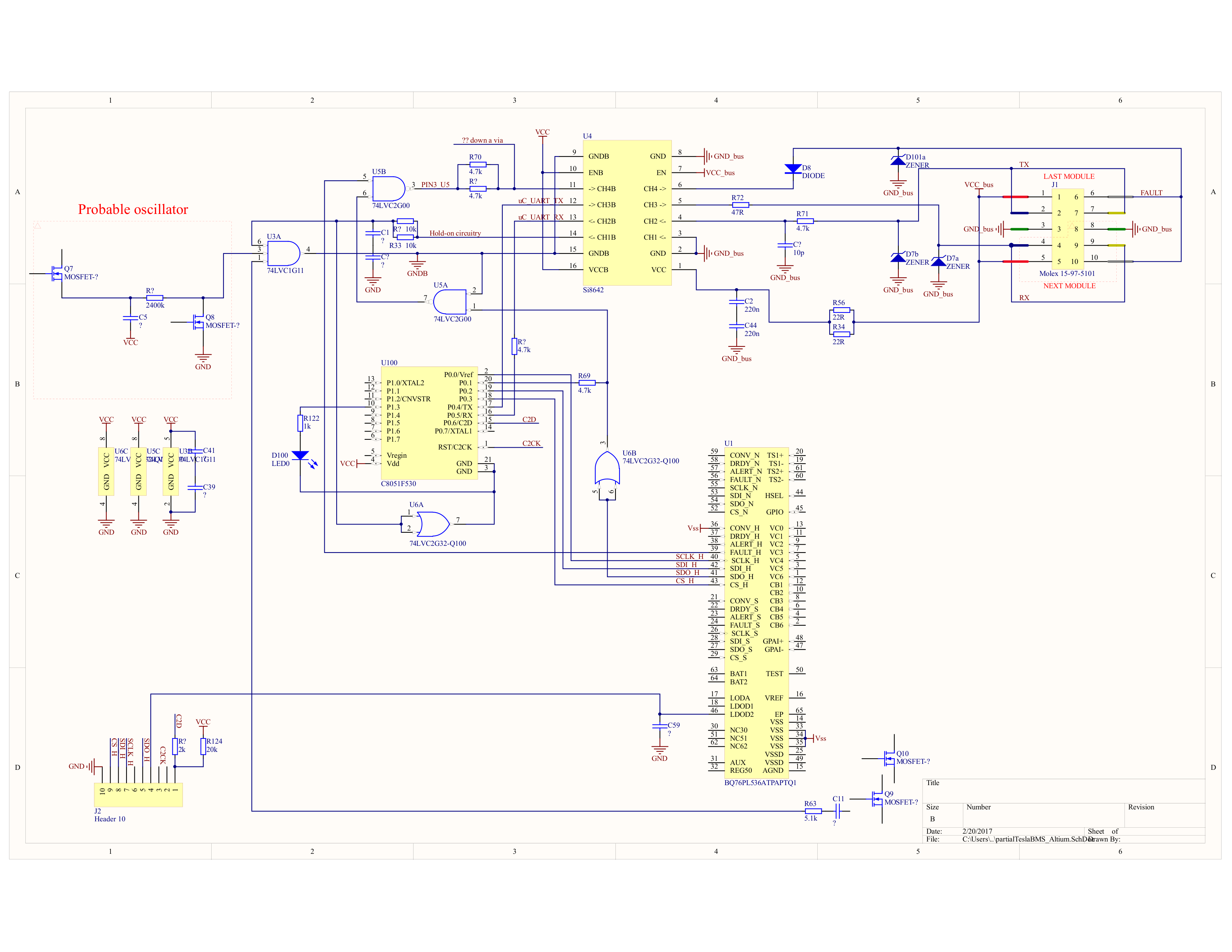
    Here is a rough schematic of the isolated bus circuitry.

    It looks like there is some shared "open collector" style bus on CH4 of the isolator, with D8 and (I assume) a pullup on the BMS controller board. But so far I've only ever measured this line being low, thus disabling the entire bus. I haven't worked out what U5 is yet. probably a dual logic gate. Maybe it combines error signals out of the BMS IC..

    Ch1 is used to bring the BMS out of low power mode. A low frequency oscillator powers up U4 periodically checking on the state of CH1. The whole thing then stays powered while CH1 is driven low (otherwise CH1 is high impedance if the bus side of the isolator is unpowered, the circuitry must detect this and shut down) I can't really be bothered tracing out much more of the circuit. the layer of varnish on everything and tracks disappearing into internal layers makes it a nightmare.

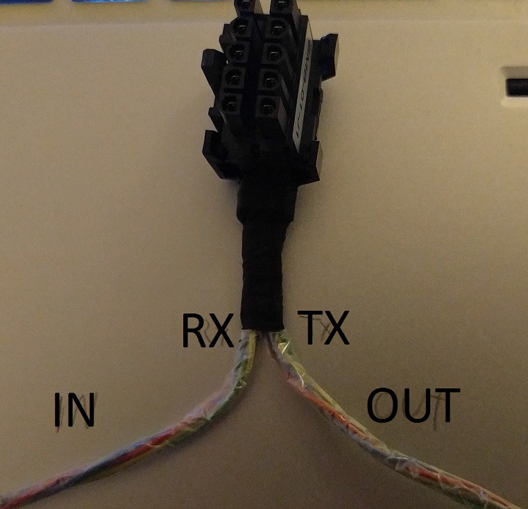
    Ch2 and 3 look like the main comms lines, connected to the UART of the uC. J1 is set up such that Tx of one channel is connected to Rx of the next, so they daisy chain together. The first BMS in the chain must get a "go" command from a controller board.. so I just have to work out how to say "go" as discussed in my last post.

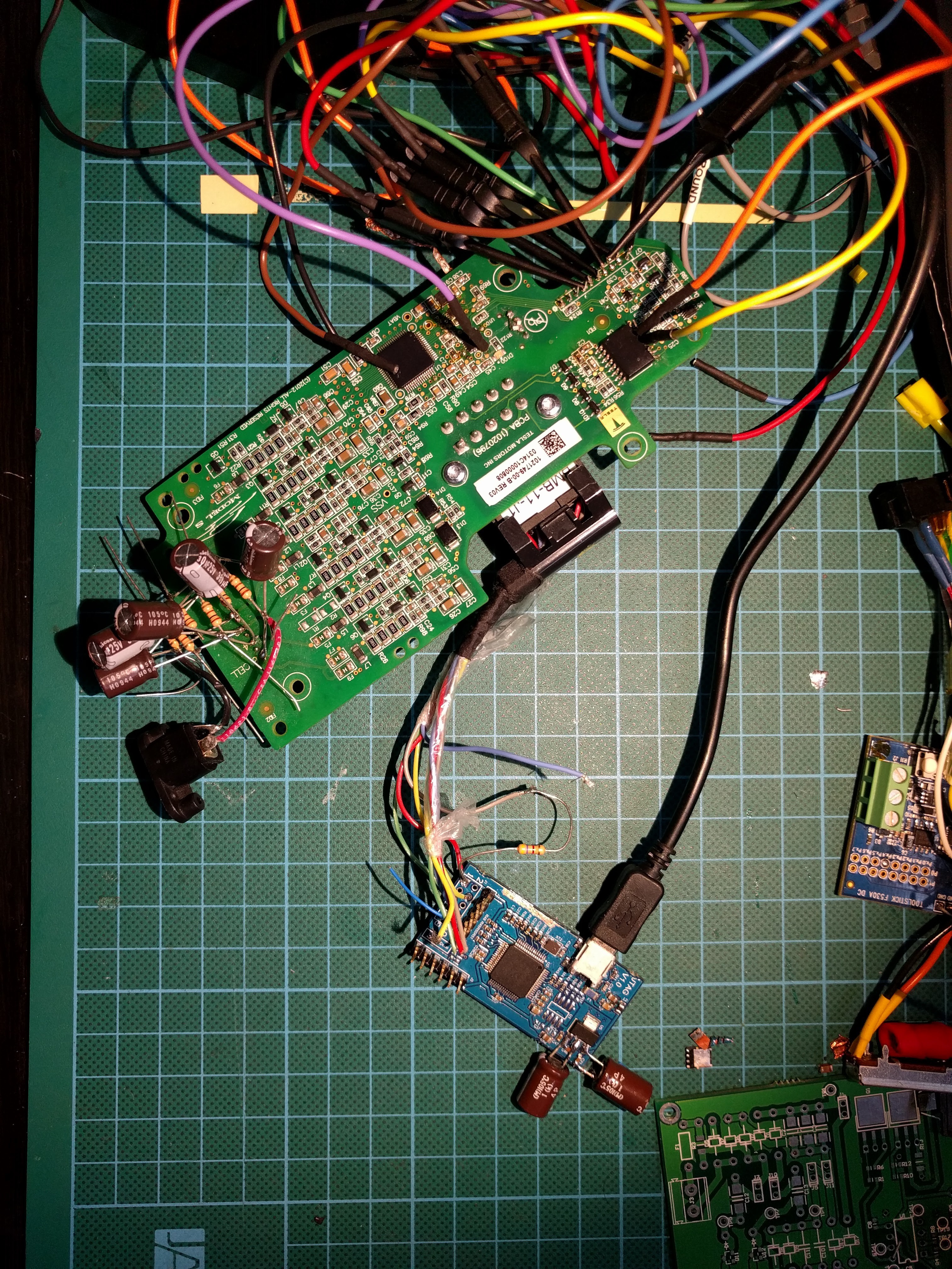
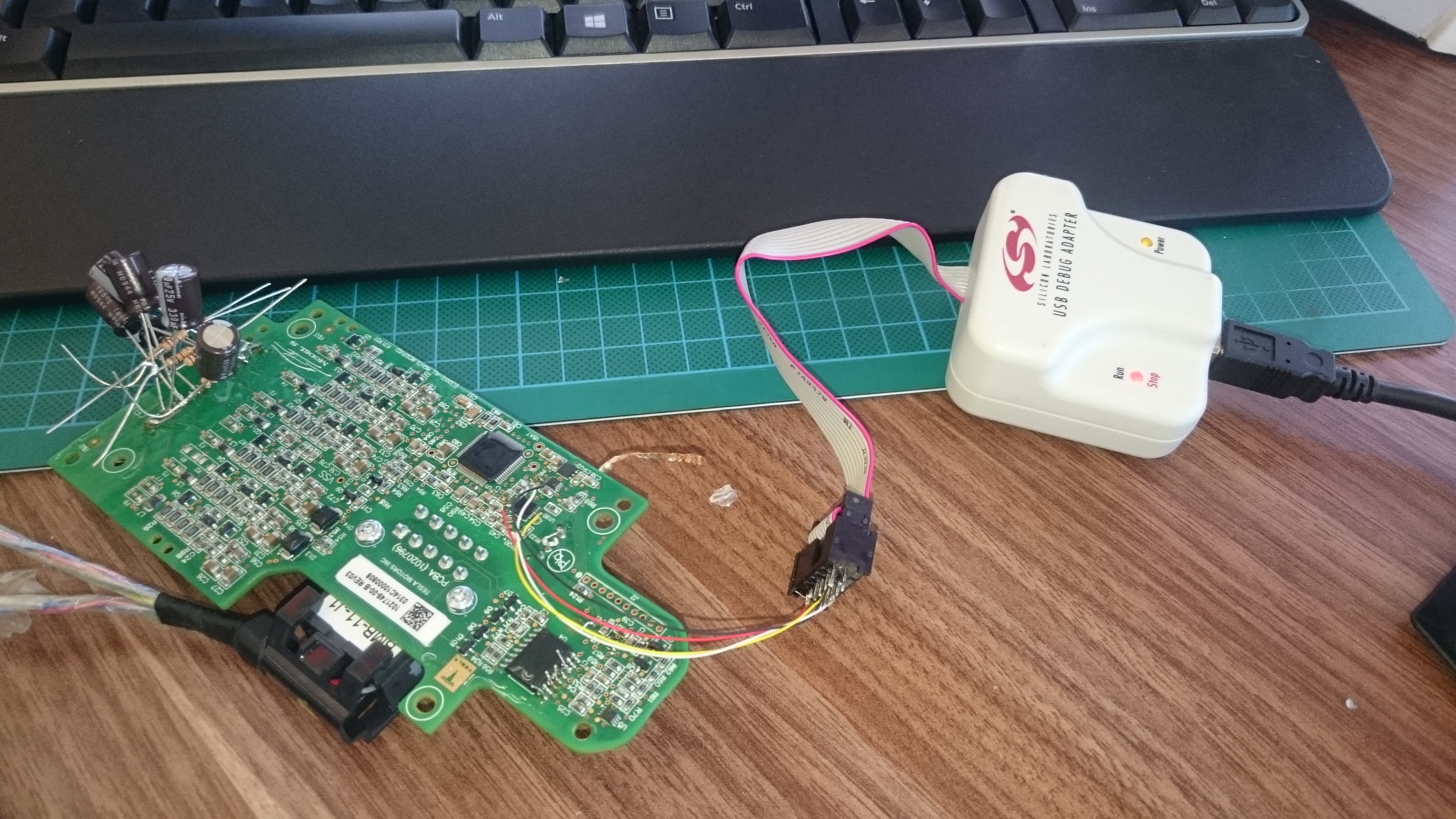
    I thought I'd just check that Tesla had the security bit set to protect the firmware from reading.. already had a SiLabs JTAG/C2 programmer so I wired up the 2-wire C2 interface.

    And turns out.. The firmware is totally readable! Tesla wanted to make my life a bit easier. Thanks Tesla! There is about 5KB of used codespace. I ran it through an 8051 disassembler, DASMx. The SiLabs C51 uC's are totally 8051 compatible, meaning binary operands and memory locations are the same, so DASMx can even decode the SFR addresses into memonics for me. Its supposed to be able to 'flatten' out the code, using all the calls and branches to make it more linear to read but it would only process 3% of the code when I tried that option.

    Here is the hex: https://cdn.hackaday.io/files/10098432032832/code.hex

    And disassembled code: https://cdn.hackaday.io/files/10098432032832/code.lst

    And the chip datasheet: https://www.silabs.com/Support Documents/TechnicalDocs/C8051F52x-F53x.pdf

    There are a few thousand lines of assembly. I started by looking at the interrupts, as some of the code is most likely interrupt driven, especially the UART RX.

    Code at 0x12A9: mov iec,#0B0H, this writes to the interrupt enable Special Function Register, enabling interrupts on Timer2 and UART0. The UART interrupt vector is 0x0023, which contains ljmp L0C0F, which does another ljmp L0DB9 which contains the code below!

    0DB9                        L0DB9:
    0DB9 : C0 E0        "  "        push    acc
    0DBB : C0 F0        "  "        push    b
    0DBD : C0 83        "  "        push    dph
    0DBF : C0 82        "  "        push    dpl
    0DC1 : C0 D0        "  "        push    psw
    0DC3 : 75 D0 00    "u  "        mov    psw,#000H
    0DC6 : C0 00        "  "        push    X0000
    0DC8 : C0 01        "  "        push    X0001
    0DCA : C0 02        "  "        push    X0002
    0DCC : C0 03        "  "        push    X0003
    0DCE : C0 04        "  "        push    X0004
    0DD0 : C0 05        "  "        push    X0005
    0DD2 : C0 06        "  "        push    X0006
    0DD4 : C0 07        "  "        push    X0007
    0DD6 : 30 99 05    "0  "        jnb    ti,L0DDE
    0DD9 : 75 2B 00    "u+ "        mov    X002B,#000H
    0DDC : C2 99        "  "        clr    ti
    0DDE                        L0DDE:
    0DDE : 30 98 30    "0 0"        jnb    ri,L0E11
    0DE1 : 85 99 2A    "  *"        mov    X002A,sbuf
    0DE4 : E5 2C        " ,"        mov    a,X002C
    0DE6 : 60 21        "`!"        jz    L0E09
    0DE8 : E5 2B        " +"        mov    a,X002B
    0DEA : 60 05        "` "        jz    L0DF1
    0DEC                        L0DEC:
    0DEC : 30 99 FD    "0  "        jnb    ti,L0DEC
    0DEF : C2 99        "  "        clr    ti
    0DF1                        L0DF1:
    0DF1 : E5 2D        " -"        mov    a,X002D
    0DF3 : 60 0D        "` "        jz    L0E02
    0DF5 : E5 2A        " *"        mov    a,X002A
    0DF7 : 54 FE        "T "        anl    a,#0FEH
    0DF9 : 70 07        "p "        jnz    L0E02
    0DFB : E5 2A        " *"        mov    a,X002A
    0DFD : 44 80        "D "        orl    a,#080H
    0DFF : FF        " "            mov    r7,a
    0E00 : 80 02        "  "        sjmp    L0E04
                    ;
    0E02                        L0E02:
    0E02 : AF 2A        " *"        mov    r7,X002A
    0E04                        L0E04:
    0E04 : 8F 99        "  "        mov    sbuf,r7
    0E06 : 75 2B 01    "u+ "        mov    X002B,#001H
    0E09                        L0E09:
    0E09 : 75 29 01    "u) "        mov    X0029,#001H
    0E0C : C2 98        "  "        clr    ri
    0E0E : 12 12 95    "   "        lcall    L1295
    0E11                        L0E11:
    0E11 : D0 07        "  "        pop    X0007
    0E13 : D0 06        "  "        pop    X0006
    0E15 : D0 05        "  "        pop    X0005
    0E17 : D0 04        "  "        pop    X0004
    0E19 : D0 03 "...
    Read more »

  • first steps

    Jarrod03/28/2016 at 20:12 0 comments

    Did some probing of the BMS and tracing out of the isolated circuitry, I think I have figured out how the basic communication bus SHOULD work..

    Looks like Tesla have powered down the uC and isolator chips to save energy when the car is turned off, they do this with a switch between the IC Vss/gnd and the TI BMS IC's Vss/gnd, looks like U5 and U5 are the switches. U2 appears to be a voltage regulator (judging by the heat it produces when powered on.)

    They have an oscillator which enables the isolator IC periodically, if the bus side of the isolator is powered, pin 14 will be pulled low, this then enables the uC and isolator until the isolated bus is unpowered and pin 14 goes high impedance. When it poweres up, the uC flashes the onboard LED, but it doesn't send out any data, in fact it pulls the data line low..

    Pin 17 of the uC is connected to an output channel of the isolator, pin 16 is connected to an input, these are UART TX/RX pins so it's a safe bet that some serial protocol is used to enable the board and read out data. and it's not just a simple

    Unfortunately it's going to take a long time to brute force the serial baudrate and combination of bytes which makes data flow.. so this is a dead end unless I can get my hands on a working Tesla with it's pack ripped open to probe the bus.. Anyone?

    Otherwise plan B is to write my own code to run on the Silabs uC and interface with the BMS IC.

View all 5 project logs

Enjoy this project?

Share

Discussions

Erland Lewin wrote 11/26/2020 at 13:55 point

FWIW, due to the digital isolator chip on the slave BMS boards, you can power them with 3.3V and use a 3.3V serial port. I hooked up a Raspberry Pi to the slave board connector directly (no voltage dividers etc) and am communicating.

Thanks for your work. I'm converting a motorboat from 1920 from diesel engine to electric, using Tesla modules: http://electric-boat.lewin.nu/

  Are you sure? yes | no

adam.santamaria wrote 01/20/2024 at 11:58 point

Hi Erland, what do you mean by "you can power them with 3.3v" ? Is there a way to power on a slave BMS board without having the cells connected ? I was thinking about setting a voltage directly on Vbat/Vss.
Thanks for your help

  Are you sure? yes | no

Erland Lewin wrote 01/20/2024 at 12:24 point

The board has an isolator for the communication (U4, Si8642 in the schematic in the post above) that needs to be powered from the device that is communicating with the slave BMS board, this is what I was referring to. I haven’t tried removing the boards from the modules.

Good Luck, fun with a reply over 3 years later!

  Are you sure? yes | no

adam.santamaria wrote 01/21/2024 at 13:17 point

Woow, I was not expecting such a quick answer :) thanks !

From my side, I am working with the BMB PCB alone. Yesterday, I finally saw some life (Green LED flashing once) by powering both the bus side from the Vcc/GND of the Molex connector, and the cells side from the Vbatt/Vss PCB access points, with a USB 5V source from my PC.
As explained in the Jarrod blog, a pull up on the Molex fault line is also required (4kOhm for me).

  Are you sure? yes | no

dieter wrote 11/02/2018 at 12:12 point

Hi Jarrod, real cool work. I built my own Tesla bat island, went live in May and stayed autonoms until now and this in Austria - real cool. 4 head houshold with 4 modules > 20KWh and 4kwp pv. All summer no need for balancing - so i let it drag. Now the need gets urgent as I reach the bottom end of my buffer.

Tried your hack with ftdi - worked more or less on the spot. Sweet! Only one important question: Bleeders do not work!

In your py script comment you turn on a bleeding switch. I tried to play around - no effect. I tried with one cell and 3-10 secs on and 5 secs off. I tried all but one cell on witht same timing - no effect:( I was expecting the cell voltage of the switched on cell to go down or at least the others to go up during loading. Exactly nothing happened. The read-out cell voltage ratio stays unchanged.

Would you have any hint before I have to pull out the lab equipment.

Thanks heaps, Dieter

  Are you sure? yes | no

svein.medhus wrote 02/04/2019 at 12:28 point

Not sure if this is helpfull to you, but keep in mind that the balancing load is only about 100mA on the Tesla BMS board in the battery module.

  Are you sure? yes | no

dieter wrote 02/26/2019 at 22:26 point

got it kind of reacting now. at least some cell voltages go up, some go down, some stay the same. still dont understand how to balance. Have to find schematics. thoght I turn the highes cell  on and the charge goes elsewhere. than repeat. at the moment I have ration of about 3:1 up to 10:1 on/off. No real effect. Do I miss somthing?

  Are you sure? yes | no

Jim Bob wrote 08/02/2020 at 21:34 point

i got balancing to work on any of the 6 cells with the ftdi python script.  verified with thermal camera.  For example, sending  0b100001 = 0x21 will turn on balancing for cell 1 and 6.  0b111111=0x3f with turn on balancing for all cells.

  Are you sure? yes | no

3tgp.mitglied wrote 05/23/2018 at 14:44 point

Great work guys!!

Is there any information about the SOC, SoH and SoF algorithms?

  Are you sure? yes | no

Jim Bob wrote 08/02/2020 at 21:34 point

i believe that is done by the master bms board, which is not located on a tesla module.

  Are you sure? yes | no

wanb1i wrote 04/27/2018 at 13:34 point

Is this project still active? There's been no activity (except me) since March? I can't seem to find any additional info on EVTV either. Any help would be appreciated.

  Are you sure? yes | no

wanb1i wrote 04/25/2018 at 21:19 point

Jarrod, I was lead to this site by EVTV. I have a Solar system on my home that the batteries are going out after 16 years, so I want to use 2 Tesla 24vdc-5.2kw/233ah battery modules I found on eBay. I'm concerned about keeping the cells balanced and I don't know if the electronics provided by the Outback Power charge controller (FM-80) or the Inverter/Chargers (FX3524) have the ability to keep the cells balanced. I can setup just about any voltage/amperage/time for the 3 phase charge cycles (Bulk, Absorption & Float), but the only balance I see in the settings is "Equalize" and I'm not sure that would be sufficient or wise. So I'm very interested in learning about this device (BMS) you are building. I have read through the discussion and I notice there seems to be a lot of interest in this device for Solar/Battery storage, so I hope that would be a consideration in it's final design.

I know a lot about solar, nothing about programming, so I would love to help where I can be useful.

Thanks again for the work you have done!

Wanbli

  Are you sure? yes | no

Luca Buccolini wrote 03/14/2018 at 22:14 point

Congrats for the project! There are some information about the cells balancing circuit?

  Are you sure? yes | no

Eric Bourlet wrote 12/13/2017 at 23:14 point

whats the status of this? Have you got the cell balancing function to work?

  Are you sure? yes | no

Jim Bob wrote 08/02/2020 at 21:35 point

it works great.

  Are you sure? yes | no

Sterling Smith wrote 07/14/2017 at 18:51 point

Awesome stuff! I'm currently working on a project where we are building a small external frame vehicle powered by Tesla hardware. Out of curiousity, how did y'all select the parameter for the Steinhart–Hart equation when reading the temperature bytes?

  Are you sure? yes | no

Jarrod wrote 08/09/2017 at 20:56 point

I don't know exactly what model of thermistor is in the module but I assume it is similar to the model specified in the 

  Are you sure? yes | no

joesidebottom wrote 02/18/2017 at 00:19 point

how far are you from getting the bms boards to balance.  I am a potential customer 

I have a few teslas and a couple battery packs. Would really like to use the tesla bms 

Do you think the bms will work if i have multiple parallel strings   of modules (48v)

I would be installing the battery packs as lead acid replacement so would like charge discharge relays 

Im no good with programming but if there is anything else you need i would be happy to help.

  Are you sure? yes | no

Jarrod wrote 02/18/2017 at 20:02 point

We will be designing a board/shield to interface with any number of modules, up to 62 modules theoretically. It should work with any configuration of the modules (series parallel). It's going to be designed with automotive in mind, ie interface via CAN bus, drive relays. But if there are any other applications with specific requirements we might consider including them. And if there is enough interest it might be feasible to do a run of assembled boards for sale. 

If you need a tested product complete with software for your specific application, maybe one of us would consider consulting for a fee. But I suspect there are other skilled individuals who might be interested in developing something similar anyway. Depends how quickly you need it and how much technical work you can put into it.

  Are you sure? yes | no

shaun.luty wrote 10/30/2017 at 23:29 point

Hi Jarrod - a few questions. The Tesla model s battery packs come fitted with a BMS board with the  battery module. From your investigations does this board still function passively when the battery module is not connected to anything external?
I.e removed from the car but internally balancing the model s modules 444 cells in a 74p6s config?

I'm considering trading up to Tesla modules to run my second house hybrid pv inverter.

Am I able to purchase the board and shield from you? Is it available for a homebrew setup?

I use the Batrium BMS from Australia that's popular with people building diy powerwalls from old 18650 tested cells.
thanks

Shaun

  Are you sure? yes | no

Collin Kidder wrote 02/12/2017 at 02:02 point

I've built a disassembler for 8051 that works better than anything I had access to. It's at https://github.com/collin80/8051Disassembler I disassembled the code.hex file and started to do annotation as I worked out what was going on. As such, some things are way over commented. The disassembled code output from that new disassembler is also in the github repo.

I've got a bunch of notes about the way it all works that I wrote on paper. I'll try to organize all of that into something coherent and start a project log entry with the details. With this new version of the disassembled code it should be easier to figure out what is going on.

  Are you sure? yes | no

Dave wrote 12/02/2016 at 21:56 point

  Are you sure? yes | no

Michel Kuenemann wrote 04/26/2016 at 06:39 point

Hello,

Your project is very interesting.

I have equipped my house with an off grid solar system two years ago. I am currently replacing the lead-acid batteries (48V - 460 Ah) with a 10 KWh (or more) 18650 Battery stack. I am designing the BMS myself. The cells are not yet purchased. Why not buy a second hand pack from a wrecked Tesla S ?

Can you tell me where I can buy one ?

My PV project is described here: 

https://hackaday.io/project/2333-my-off-grid-solar-system-monitoring

Thanks a lot

Regards,

Michel

  Are you sure? yes | no

Jarrod wrote 05/03/2016 at 06:04 point

Search Ebay. I bought mine from seller k-ash. All the packs I bought measured >4.5kWh

  Are you sure? yes | no

Similar Projects

Does this project spark your interest?

Become a member to follow this project and never miss any updates