Close
0%
0%

Direct UV Printer for Alternative Photography

Design of a UV printer for making exposures of Alternative Photography prints, direct from a digital image

Similar projects worth following
NOTE: Project has been re-booted, existing work will be largely recycled in development of the new project.

This project is for the design of a prototype direct UV printer for use in Alternative Photography.

The design aim is to achieve minimum of;
- 256 levels exposure
- circa 750 dpi resolution
- bed width of ~400mm, to accommodate reasonable sized prints (pretty flexible on this)

The core of the machine is a Raspberry Pi Zero for data processing and control, coupled with a Arduino Nano 3 to act as an I/O expander on the print head. Exposure will be made with a UV laser and 8bit programmable control system for the output power.

A number of the component PCBs will be broken out to separate project pages, with all of the data required to reproduce them. Please see the links below, or my other projects.

This device is envisaged as another tool available to print makers, not as a replacement to the many existing ways of making prints.

Shared under the Creative Commons - Attribution - ShareAlike 3.0 license.

Code for the Arduino and Raspberry Pi now up on GitHub - very much work in progress

Overview;

The printer consists of the following parts; Data processing & overall control, a pair of stepper motors to control paper feed (rigid base board carrier) and print head translation and finally the print head itself. In order to attain the desired image resolution, the print head spinning mirror will scan a width of roughly 5mm, to generate a strip similar to that from an inkjet printer. The strips are then built up to form the completed image.

This is the current layout for the various modules (continued below the break).
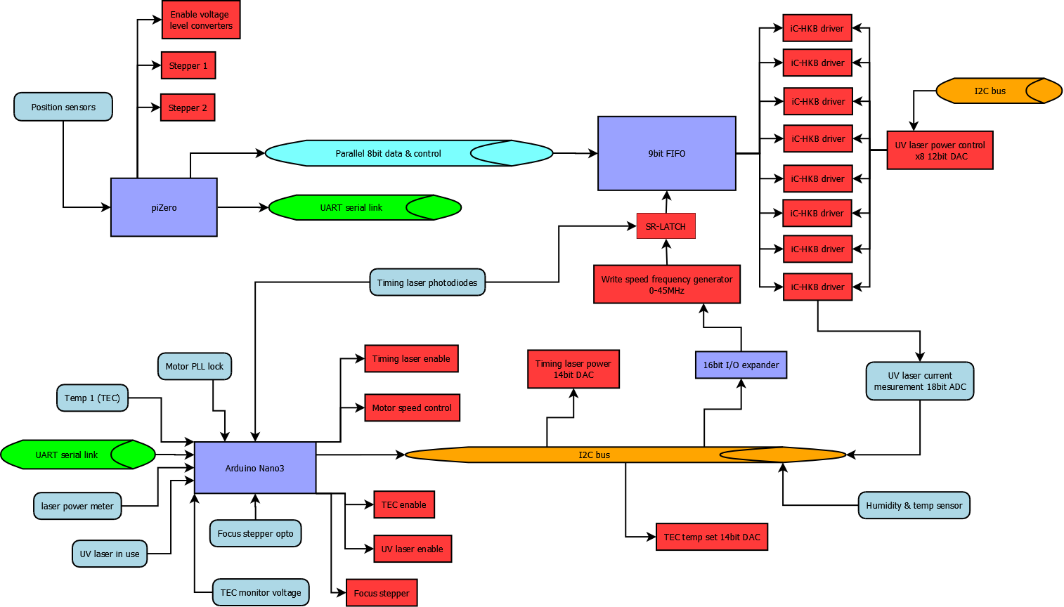
Figure - System overview (click to expand for more detail)

Background;

The Iron based photographic printing (Siderotype) process dates back to the Herschel Cyanotype, better known as blueprint; which uses the sensitivity to UV light of specific Iron compounds to produce a print. There are numerous other 'alternative' photographic processes many of which should also be suitable.

With the advent of digital cameras it is necessary to print negatives onto transparency film, to allow contact printing, similarly when making enlargements, smaller negatives are scanned and then printed to transparency film.

However printer ink is designed for visible wavelengths and its response to UV wavelengths is variable enough between batches to require repeated time consuming calibration. The transparency film and inks are also fairly costly. The aim for this project is to remove them from the equation, and thus simplify the process from finalising an image to being able to process it. At the same time, allowing full scope in choice of chemistry and media.

I've had questions regarding using this method with other printing chemistry methods such as tintypes. Any chemistry that is sensitive to UV and does not have a very short life-span (wet plates may be possible with humidity control) should be viable. The more sensitive the chemistry, the faster the process should print, up to the limits of the electronics; laser power/signalling speed trade off.

Read more »

Mathcad - Exposure calculations A2.pdf

Exposure duration calculations for Kallitype and Cyanotype methods

Adobe Portable Document Format - 41.01 kB - 03/12/2016 at 03:14

Preview

BDR-209 test data.jpg

BDR-206 x16 bluray laser diode test data

JPEG Image - 129.84 kB - 06/28/2016 at 23:34

Preview

BDR-209 600mw 405nm.STEP

Laser diode geometry

step - 72.09 kB - 06/28/2016 at 23:36

Download

  • !Abandoned! - Please see project description at top of page

    David Brown11/07/2018 at 02:28 1 comment

    as above

  • Frame coming together

    David Brown04/14/2017 at 22:05 0 comments

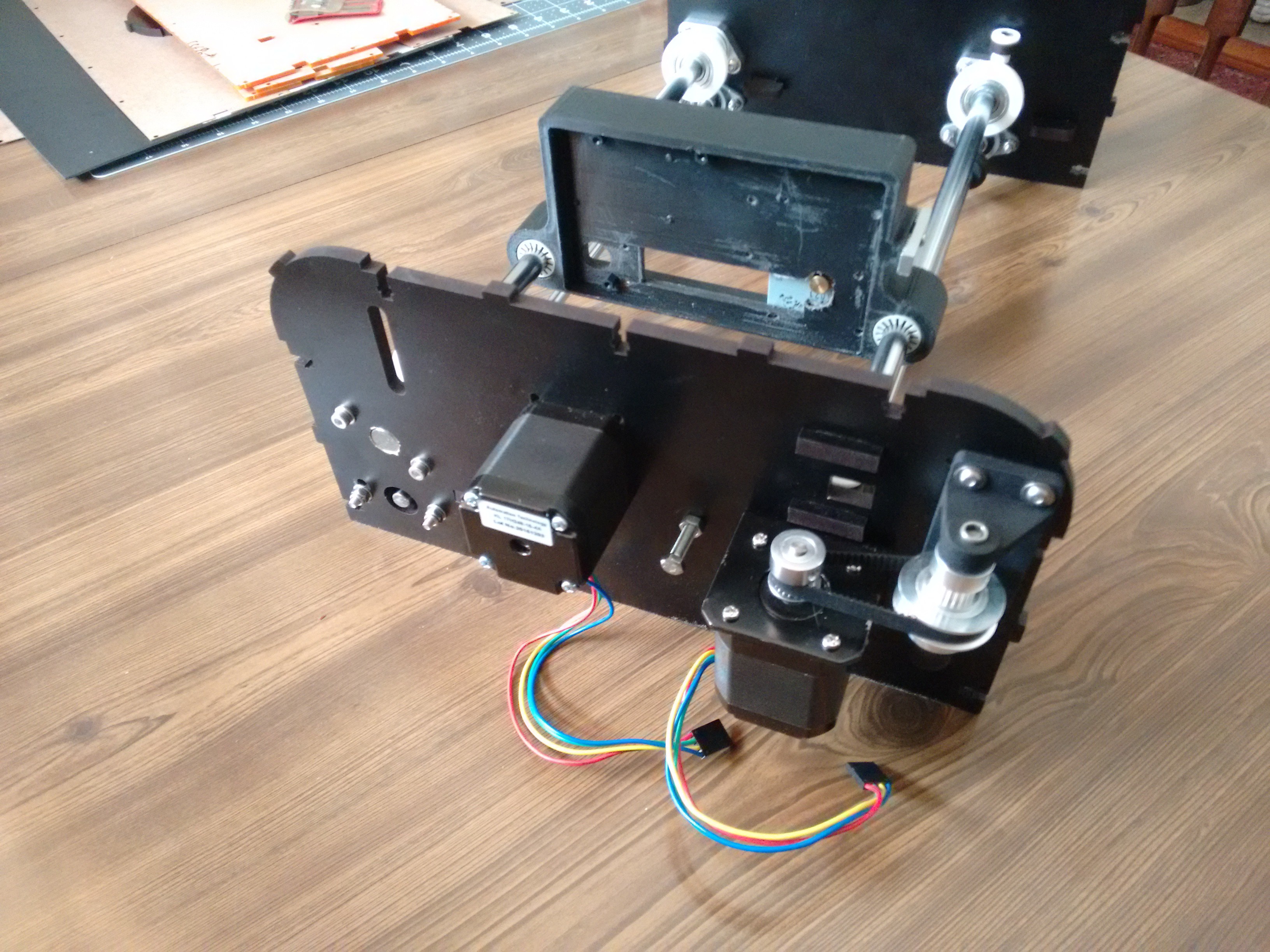
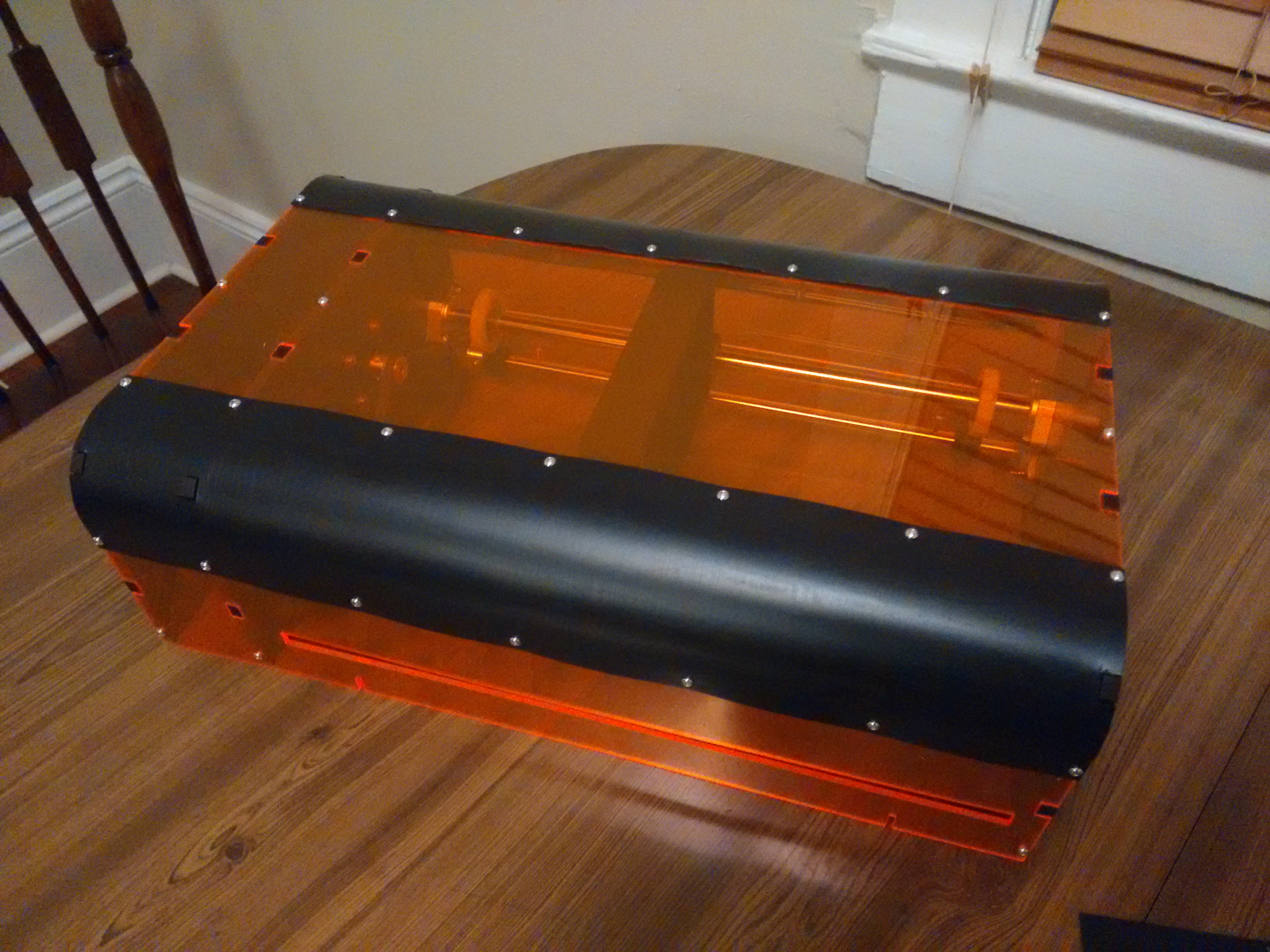
    i thought I would share some (poor) photos of the frame coming together.

    I've added an idler pulley to take up a little slack and increase the angle of contact on the driving cog.

    On the electrical side i'm planning on bypassing the FIFO and using an atmega to generate signals, and cutout the raspberry pi zero. This is because I know that the current design iteration is not up to the job, but will be useful for running experiments that will allow development to continue. I'm more familiar with AVR for programming so that will make setting up data logging etc. for tests easier.

    I'm also considering ways to get funds to allow faster development time. Where I am at the moment, I don't think there is scope for the likes of kickstarter as its not yet at the functional prototype stage. Patreon may be an option, but I have only glanced at their site. Any thoughts and comments welcome.

    Edit - Put the casing plates together; it's nice when tolerance gaps work correctly.

  • laser head buildup

    David Brown04/06/2017 at 15:53 0 comments

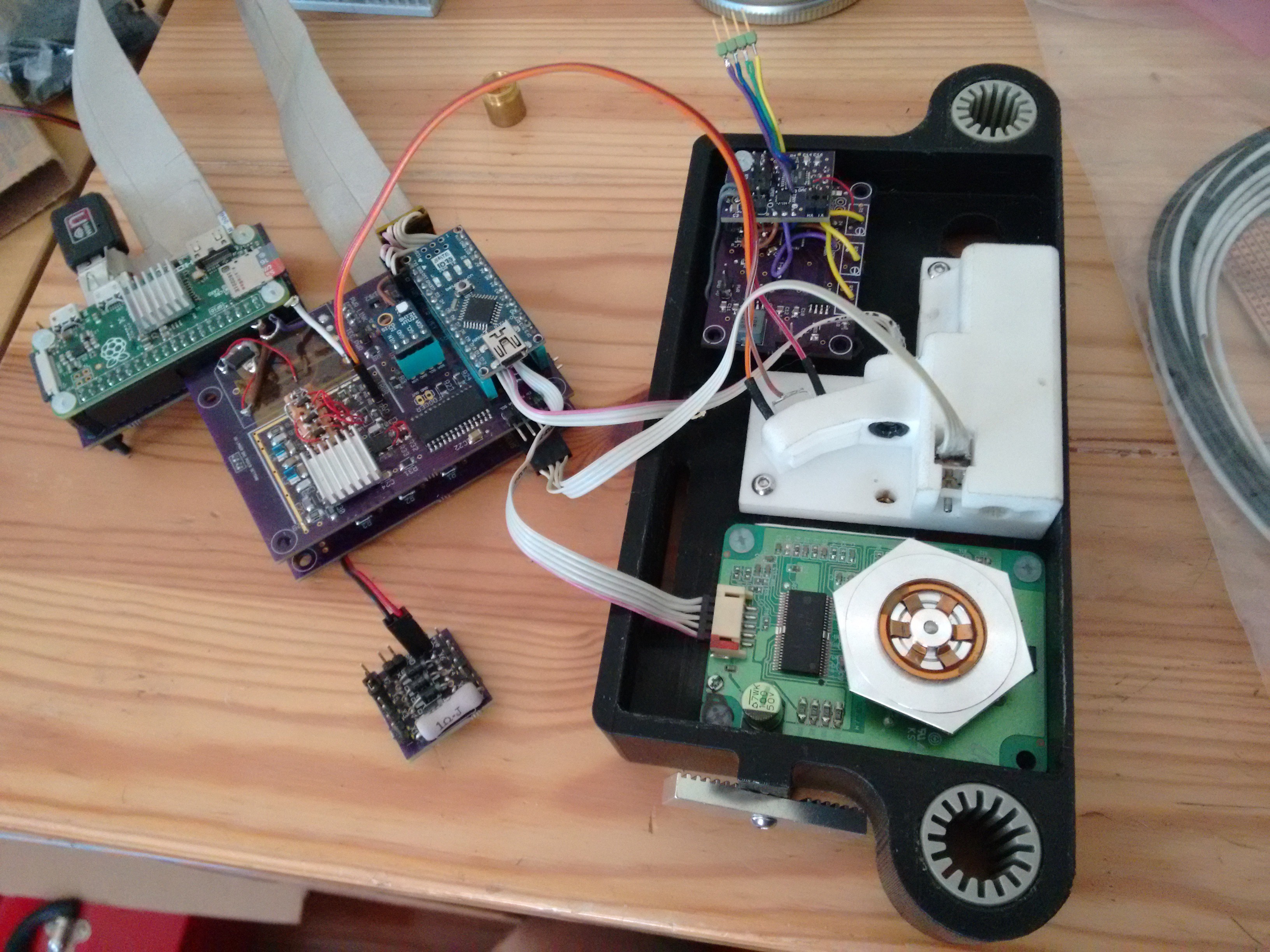
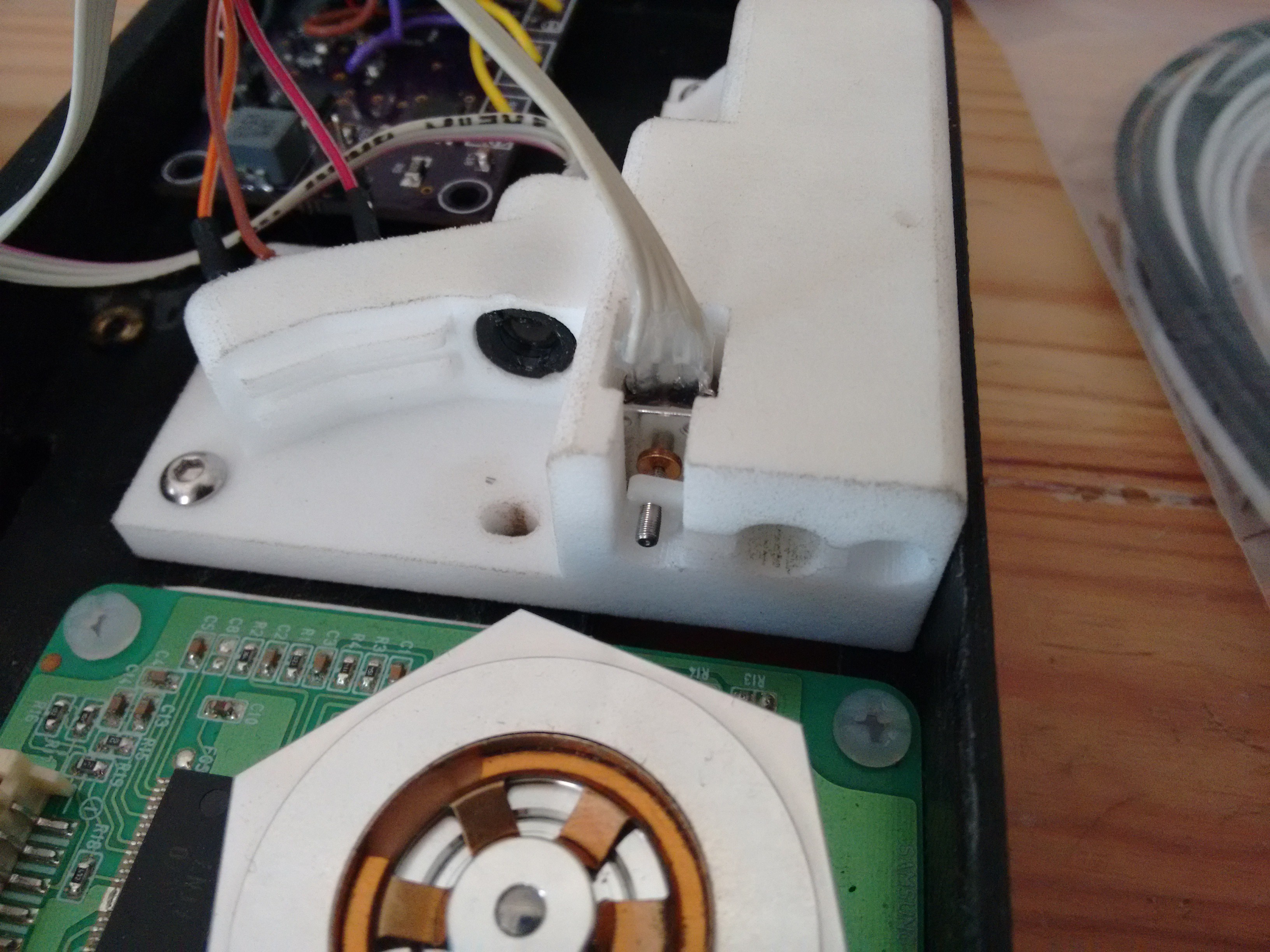
    I've received the 3D printed parts, so i've been building up the components of the laser head. The high definition nylon prints are good, but dissapointed by the large black casing as its not a solid print so fitting the metal screw inserts has been a pain. For the cost next time i need larger scale parts i'll just invest in a printer and do it myself.

    I'm still awaiting some more nuts & bolts to assemble the frame

    The trigger laser now works and will be trimmed by having leading zeros in the FIFO to allow accurate position calibration.

    The micro stepper fitted well and will do a good job allowing the focus to be adjusted. I've yet to fit the beam tube and output lens.

  • Ordered the printed parts

    David Brown02/05/2017 at 16:37 0 comments

    So i've placed an order for the printed components so those should come through from Shapeway next month, and i'll get the cut parts ordered shortly.

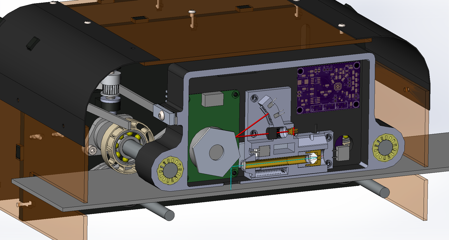
    To give an overview of where this is at here are some cut-away, firstly of the print head;

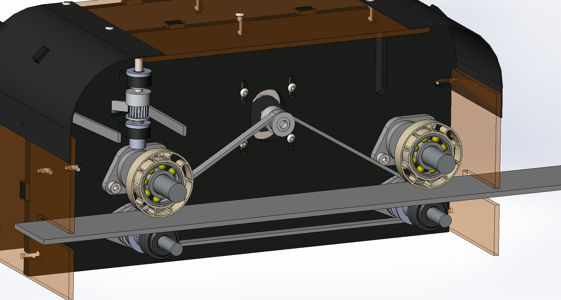
    Then the base plate drive system, onto which the paper is taped down. This is likely to be a piece of tempered glass, which can be easily cleaned of any chemical contamination build up from the papers;

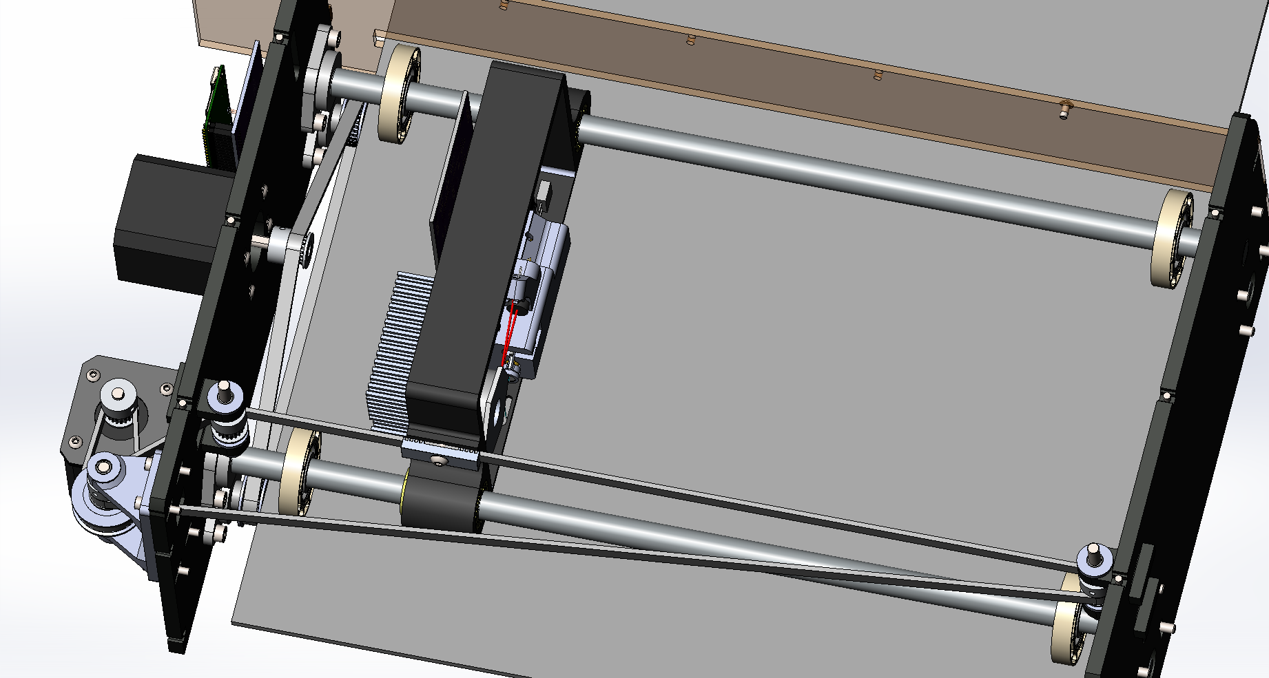
    And finally an top view of the head drive system, with gearing and tension take-up bracket on the lower left side;

    I still need to do a bit of design work on the end stops and positioning for the head and base plate.

  • looking forward

    David Brown12/17/2016 at 23:44 0 comments

    I will hopefully be able to make some progress in the new year, and get a physical prototype built up. I've been iterating through various options for building the laser head with only access to hacksaw, cordless drill and online 3D-printing and laser cutting services (I know some would suggest signing up to open access workshop, but it is just not cost justifiable).

    Figure: updated holder block

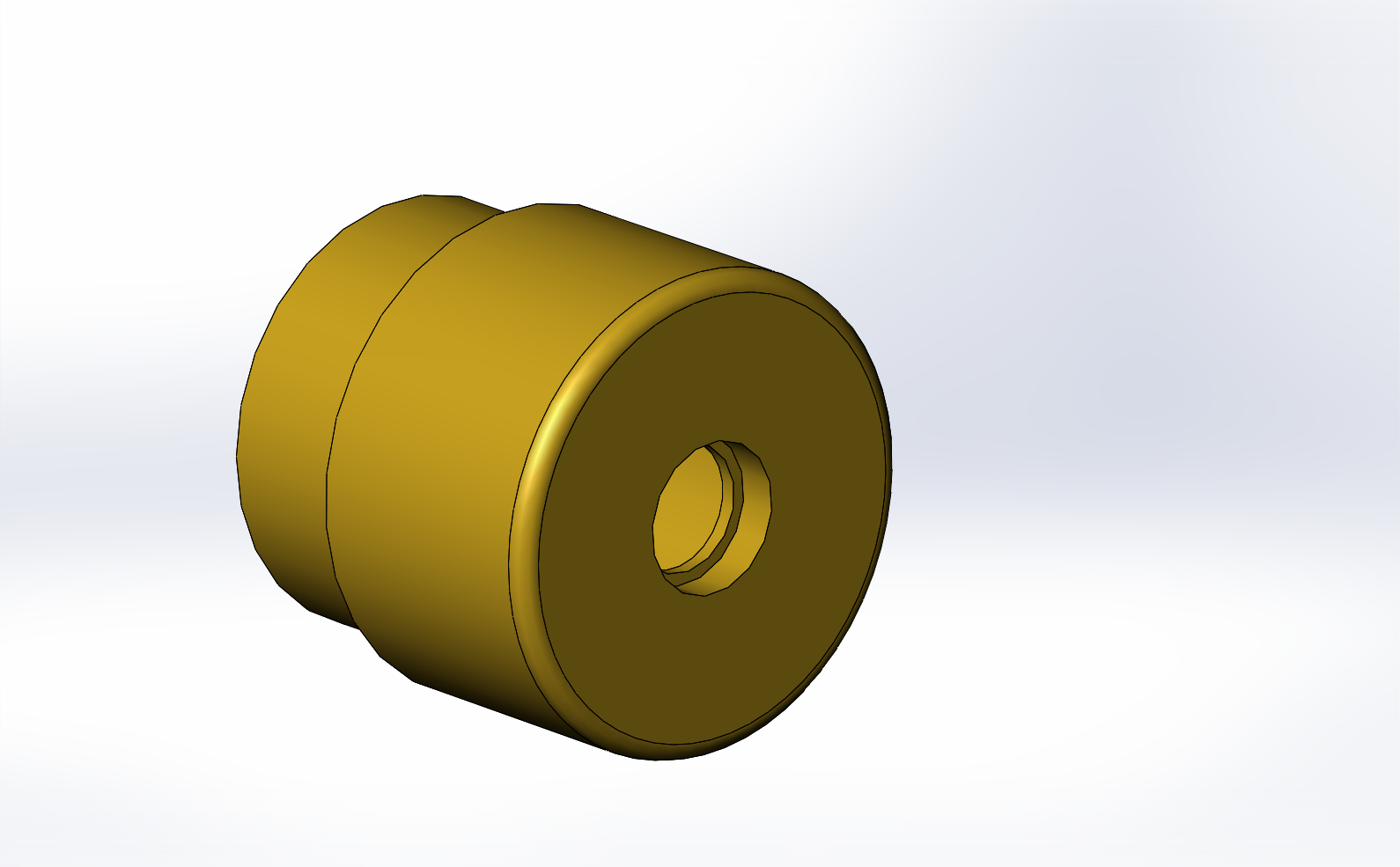
    The most recent iteration makes use of a brass TO-38 laser diode tubular housing, which then allows a fitting piece to couple the collimating lens and bellows tube to the housing. The plan is then to cast a heat sink block using copper powder/fillings and epoxy to couple the brass housing to the TEC module. This avoids the need for custom machining or printing of an aluminium heat sink.

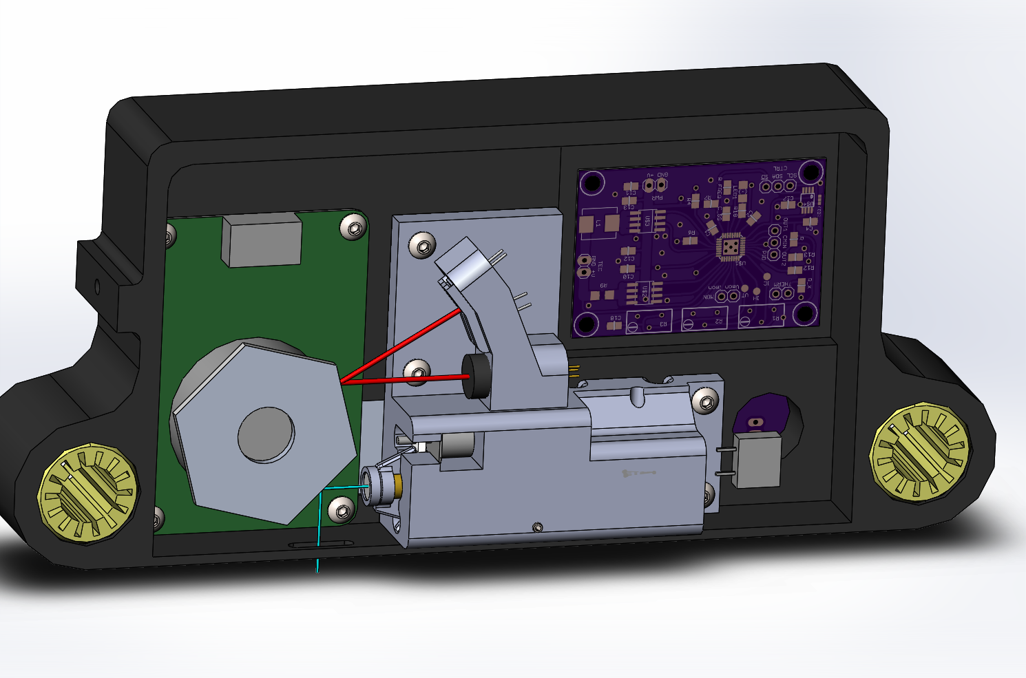
    The focusing stepper has also been moved so that it no longer clashes with the trigger laser beam (red).

    Figure: Cut-away view showing new internal layout

    Figure: TO-38 diode holder off ebay (rough dimensions, needs to be measured)

    Looking forward I know that for the current design I am going to have issues with signal propagation and loss of integrity for the high speed switching of the laser, amongst other things.

    However at this stage the whole system needs to be run to allow an accurate evaluation of which areas need the most attention, to measure the actual behaviour of the printing chemicals. Which will give a guide to power, pulse duration based on physical data, and allow a comparison with the theoretical calculations. And once I have the hardware, then it is easier to upgrade and test the control electronics.

  • lemon soaked paper napkins

    David Brown08/29/2016 at 20:44 0 comments

    Well, my long shot at securing some funds to get this project moved forward to hardware fell through, mildly enthusiastic congratulations to those moving forward to the next round.

    To make reference to hitchhikers guide to the galaxy, the odds of intelligent life evolving, proceeding to develop and eventually provide lemon soaked paper napkins following the logic of the probability of something occurring approaches 1 and time approaches infinity.

    So may be a while before the physical aspects progress, there will be progress. I will continue to work on the design and coding aspects.

  • Resiliency on UART data - implementing CRC

    David Brown08/09/2016 at 02:58 0 comments

    The communication system between the controller (rPiZero) and print head (Arduino) I decided to simplify the code in the head by using low level functions. These take the hex code strings and pass them directly to the devices or trigger other functions. This allows flexibility and reduces the data that needs to be sent.

    I've chosen a standard of 6 byte string with the first byte being the command, then up to four data bytes and finally a CRC byte.

    When designing the communication between the head and the raspberry pi, I decided to include a level of error checking on the data passed, as my initial testing showed that signal integrity may be an issue. This has not proven to be a problem thus far. Anyway having a check is good practice. Also the setup process is not a time critical process but one bit wrong could cause problems with setup of the laser diode DACs and thus possible damage to the damage (means I can't blame my typos on interference).

    In my research in learning about CRCs I've found the following references useful;

    The linked paper is interesting as the author has investigated the design space for a huge range of data lengths and code lengths, with the resulting corruption bit length protection. It turns out that the selection of CRC code has a huge impact on the resiliency afforded.

    Whilst i'm not gong to try and explain how CRCs work; see the links and your own searches. Essentially there is a balance between the number of bits protected, the number of errors detected and the number of bits in the CRC polynomial.

    In my case there is 5x 8bits of data (40bits), i'm using standard 8bit bytes so the CRC can be up to 8bits (may as well use them all). So in my case the 8-bit polynomial 0x83 also known as ATM-8 or CRC-8P is the bet option as it give protection of noticing if up to 4 bits are corrupted and is good for up to 119bits of data length.

    If I could send only 7bits easily for the code I would thus use the polynomial 0x5B also known as CRC-7F/4.2 which can protect up to 56bits. This would then save 1bit per transmission/packet which in some situations may be a worth while saving.

    Read more »

  • Mechanics progress

    David Brown08/03/2016 at 19:03 0 comments

    Over the last month or so i've been mulling over the options for the hardware / mechanics. I've decided to design around off-the-shelf components that I can get off ebay, laser cut flat materials and 3D printed components. As I only have 2ft x 2ft work area (not including the kitchen table) and basic hand tools at my disposal, something that has taken some adjustment.

    The two primary rails for the print head are fixed, with four bearings with press fit 'tyres' that ensure that the base-board is the correct distance from the print head. Ive decided to use graphite brass bushings rather than linear bearings as the Chinese ones sound dreadful and i've only been able to source one SKF at a reasonable price so far.

    Below them is another pair of rails held by bearings with a degree of adjustment capability to allow take up to the upper wheels. This pair are driven by a pair of 32T GT2 pulleys. The drive rollers will be 3D-printed bobbins with groves for o-rings that will provide grip to drive the base board through the printer.

    The paper drive tension is adjusted by the slotted stepper mount and the head translate is tensioned by slotted mounts for the reduction pulley holder.

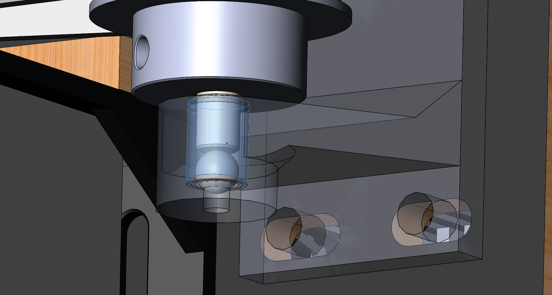
    The pulleys are mounted via Teflon coated brass bushings using 3D printed holders with the lower end of the shaft resting on a ball bearing placed within the bore of the bushing; see below.

    Bushing mount, bush and ball bearing supporting the shaft end.

    The geometry for some of the mounts is not exact and will need updating from the actual components, once in hand.

  • UV laser diode TEC controller

    David Brown07/29/2016 at 18:41 0 comments

    I've added a project update for the TEC controller that i'm developing, that's used to control the temperature of the UV laser diode. Firstly to prevent it from burning out and secondly to minimise the power output variation due to temperature changes. Update link

  • Trigger laser angle adjustment

    David Brown07/27/2016 at 00:32 0 comments

    So, having thought through the trigger system i've been working out ways to introduce some capacity for adjustment of the angles, but without affecting the rigidity of the arrangement and relative angles to the UV laser beam.

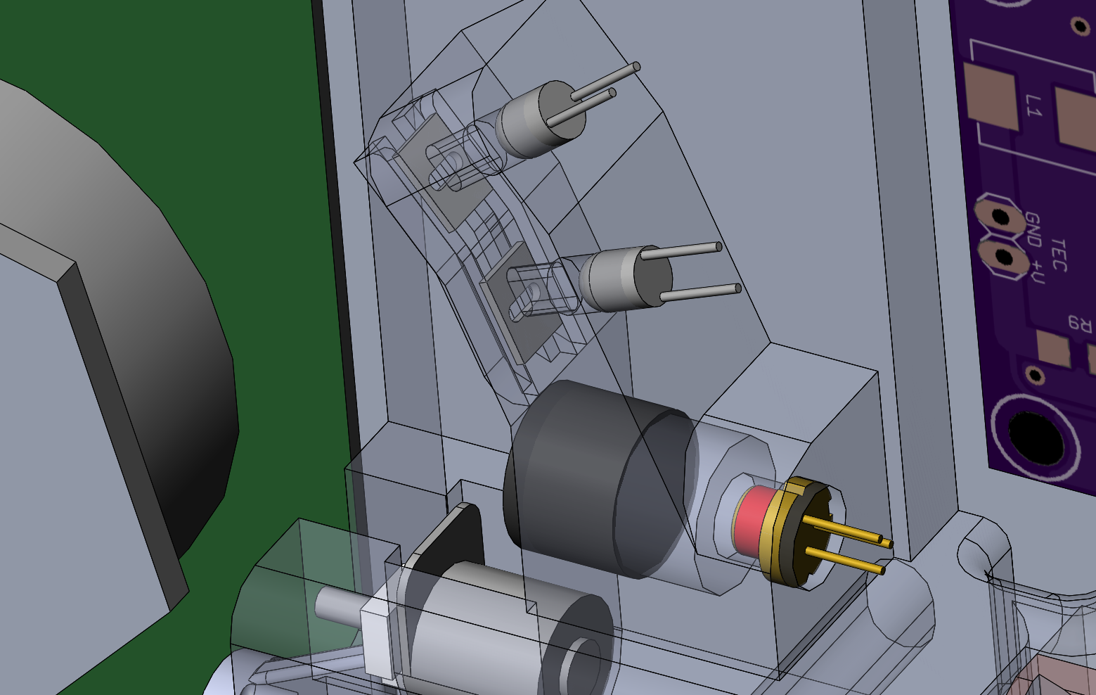
    The solution i've come up with is to expand the circular openings into slots, with a slider with perpendicular slot. This allows a small amount of adjustment as the lens of the photo-diode should cope with the off axis beam. There is additional adjustment scope in padding zeros to the beginning of the UV laser data stream.

    The image below shows the two photo-diodes (on / off via the SR latch) and the trigger laser diode and collimating lens all facing one of the faces of the polygon mirror.

View all 34 project logs

Enjoy this project?

Share

Discussions

greg7mdp wrote 11/23/2023 at 17:13 point

Is this project completely dead? I was excited by the possibilities with this. Any alternative?

  Are you sure? yes | no

altair62 wrote 05/16/2018 at 14:47 point

Hello David,
the project is very interesting! Just to understand some features of the machine: is the speed of the print head constant? how many mm / sec? I understood that the power of the laser is controlled with the PWM technique, at which frequency?
In your opinion, is it possible to try to achieve something similar only with an Aruino controller and a scan line by line, without mirrors?
Thank you for your attention, congratulations on the project!

Tiziano

  Are you sure? yes | no

moblmvrk wrote 12/27/2016 at 13:44 point
Good afternoon David, I am interested in your project. After viewing the other comments may I ask if you considered a "plot" style printer, moving the head assy but keeping the paper fixed/flat? Also, have you considered running the core functions off of a Xynq FPGA? Best of luck in your project

  Are you sure? yes | no

David Brown wrote 04/14/2017 at 22:16 point

Yes, as I have progressed i've come to realise that I need to use a CPLD/FPGA with RAM in the head to get the data rates required. I'm progressing with what I have designed to date as I can run experiments with the laser and log conditions etc. before moving on to the next iteration.

I will consider the plot style, it will simplify some aspects, and as this is using a base board to secure the paper anyway, the footprint required when printing would actually decrease.

As with these things development funds are limiting factor, so I need to make the most of what is done already, before moving to the next cycle.

  Are you sure? yes | no

moblmvrk wrote 12/27/2016 at 13:44 point
Good afternoon David, I am interested in your project. After viewing the other comments may I ask if you considered a "plot" style printer, moving the head assy but keeping the paper fixed/flat? Also, have you considered running the core functions off of a Xynq FPGA? Best of luck in your project

  Are you sure? yes | no

a.genchev wrote 11/06/2016 at 11:30 point

Hello, nice project, great efforts, but what I didn't understand was why you have so many (misterious to me) "IC-HKB driver" blocks in your scheme ? Probably you control the LD current for each pulse ?

I ask, because I have my personal, not public LASER exposer project where I developed my own LD driver (targeted to work at 6 MHz/40..450mA) w/o so much complexity - it has just DAC controlled precise voltage source, sensing resistor for checking the current before each scan-line and one dirt cheap 20 nS,push-pull,bipolar MOSFET driver to switch the diode on/off. 

I don't control gray levels, but if I had to, I would use the ink to integrate between N consecutive scans, hiding the "exposed enough" points and tunning the power per scanline. Or is your ink so sensitive that 1 pass (at what mirror RPMs? ) is enough ?

  Are you sure? yes | no

David Brown wrote 04/14/2017 at 22:23 point

The IC-HKB laser diode drivers are 1 per bit, and allow the levels to be individually tuned. So for the 8bit code they are enabled as required for each pixel as the scan progresses. So the laser output power can be controlled by sinking the sum total of the drivers.

The chemicals are sensitive enough that a single pixel exposure is sufficient.

  Are you sure? yes | no

Andy Oliver wrote 09/16/2016 at 18:05 point

I just want to lend some supportive words; I had a similar idea some time back, so of course I think this is an excellent project. I never pursued my idea beyond a sketch in a notebook, so I wish this project all the best.

  Are you sure? yes | no

Graeme Barton wrote 08/27/2016 at 23:54 point

Looks amazing. Would be interested in a kit should it become available

  Are you sure? yes | no

Graeme Barton wrote 08/27/2016 at 23:54 point

Looks amazing. Would be interested in a kit should it become available

  Are you sure? yes | no

greg7mdp wrote 07/30/2016 at 12:47 point

Fantastic project. Please mark me down for a kit or assembled unit if available, I would definitely love to get one.

  Are you sure? yes | no

David Brown wrote 07/30/2016 at 19:30 point

Thank you for your interest. All of the information to re-create the prototype will be made available here. What I would like to do is use the prototype to evaluate what is actually required and undertake a second round of design / optimization to reduce the component count and cost of the materials / identify sources for the less off-the-shelf components. At that stage it would be possible to consider kits/assembled units.

  Are you sure? yes | no

Caleb Savage wrote 07/08/2016 at 16:35 point

What an interesting project! It's a bit beyond the limits of my understanding and capability on the electronics side. What's a ballpark price range for all the components, and would you be interested in selling to the public at all either as a kit or as an assembled unit?

  Are you sure? yes | no

David Brown wrote 07/08/2016 at 16:54 point

Thank you, price range is too early to gauge, I need to get the prototype developed and working before evaluating where parts can be simplified / alternative components used. If there is the interest then i'll look at the options available.

  Are you sure? yes | no

Peter Hanely wrote 05/02/2016 at 17:01 point

Reading the exposure calculations, would 2.6s per square inch be a reasonable estimate of print speed?  Any estimate of per page operating costs?

  Are you sure? yes | no

David Brown wrote 06/28/2016 at 14:39 point

Somewhat slower unfortunately, spot area is circa 111um^2  with an exposure time of 2.62us, which converts to 0.066 square inches per second. The limiting factor is laser power and wavelength. Wavelength has a big influence (ideal would be around 350nm) on the chemistry - which is inherently slow, and part of the reason these processes died out.

This machine will be much slower than current process of print transparency negative on inkjet, make exposure, process. But on the upside, being able to locally control the intensity and to a degree the duration to a much greater level than can be achieved with a printed negative. The repeatability is then based solely on the chemistry and media choices, and not the whims of the printer ink suppliers.
Operating cost is massively dependent on chemistry and media (paper) choice, you can go from Cyanotype on newspaper (peanuts) to platinum on Arches Platine (dollars/pounds per 8x10). In terms of making an exposure, total electrical power should be in the low 10's of watts.

  Are you sure? yes | no

Similar Projects

Does this project spark your interest?

Become a member to follow this project and never miss any updates