Sergei V. Bogdanov
-
Making Five Link Mechanism Model with 2 servos
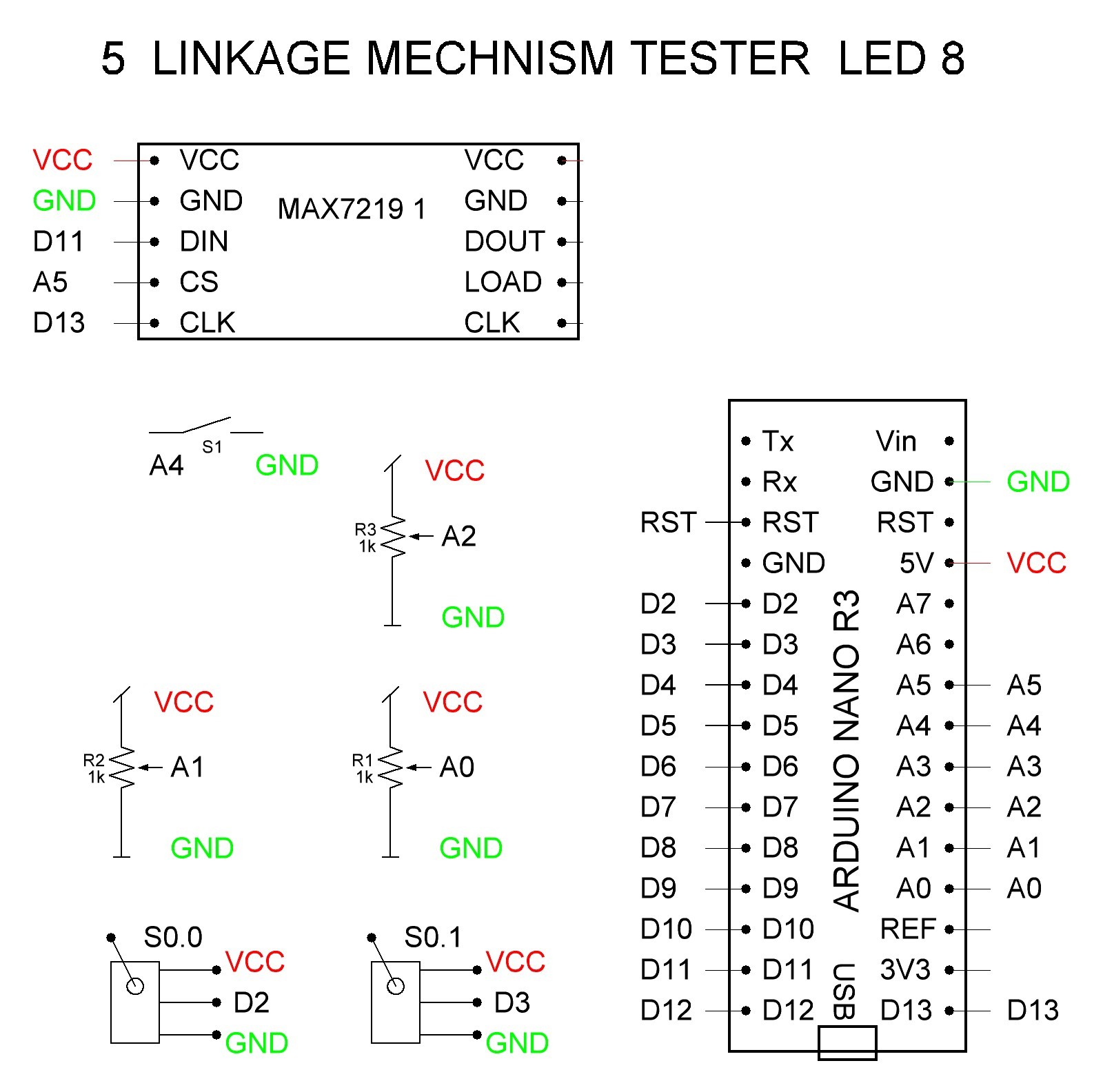
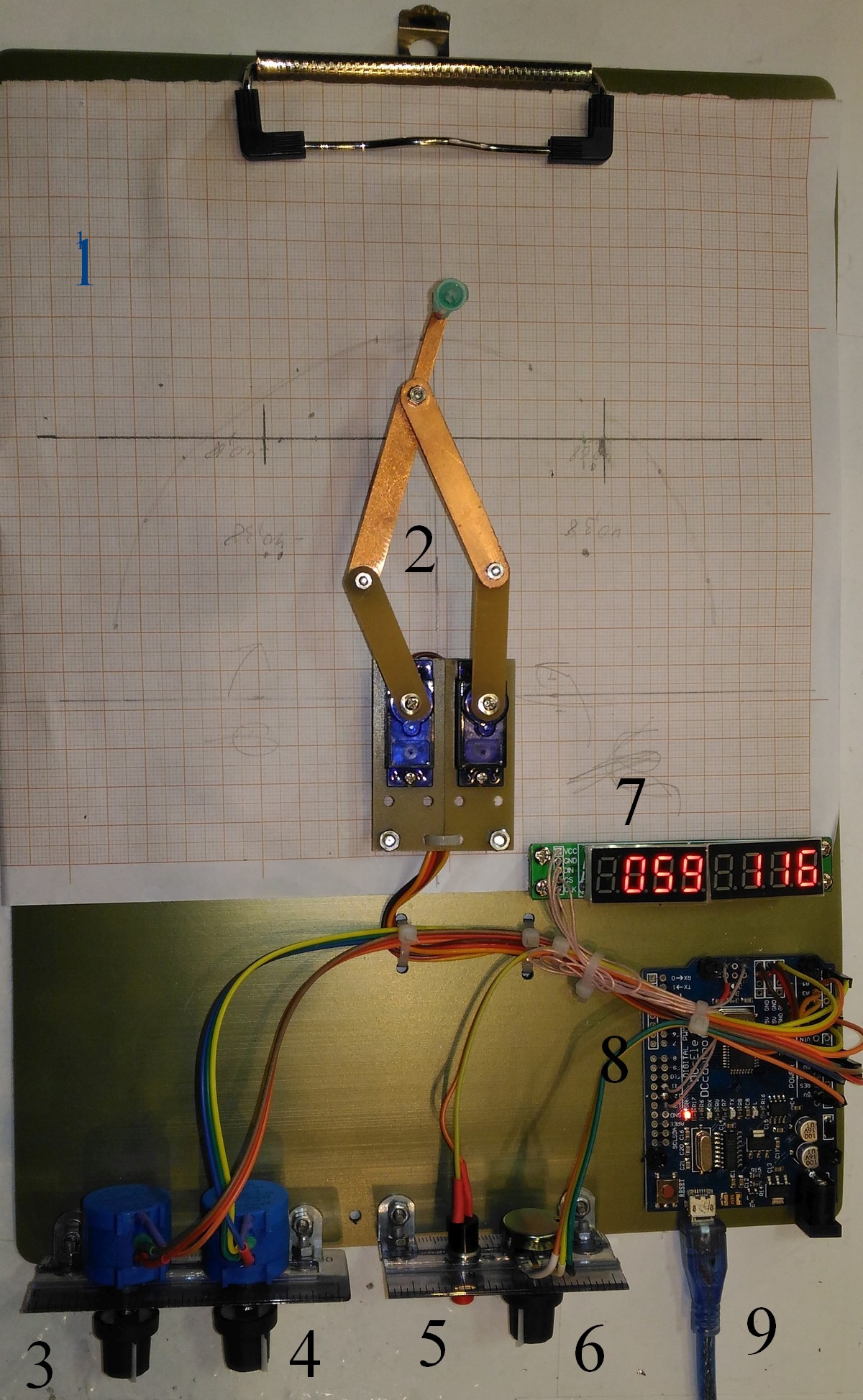
04/12/2018 at 20:02 • 0 commentsWe make model with LED display. We use folder tablet for paper as an base, and diagram millimeter paper. Let us see the schematics and the photo of the Model. We use plane We can tune the angles of servos ϕ and ψ by means of multy-turn potenriometers 3 and 4 , connected with A0 and A1 Arduino Uno inputs, toggle button 4 for mode switch and one single-turn potentiometer to control the speed in “Auto” mode. Here we use two 4-symbole LED display 7.
![]()
![]()
-
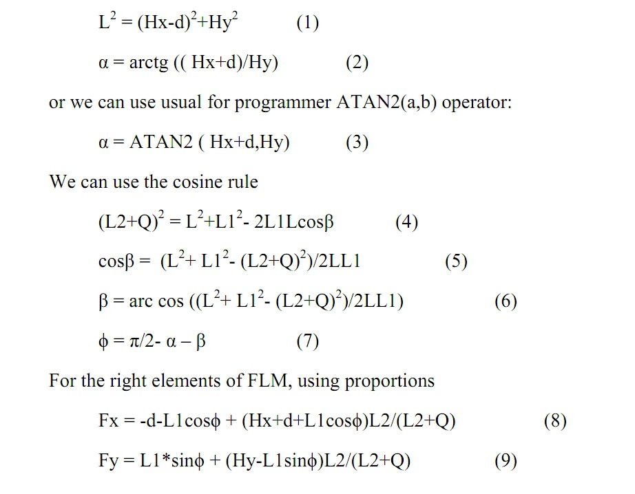
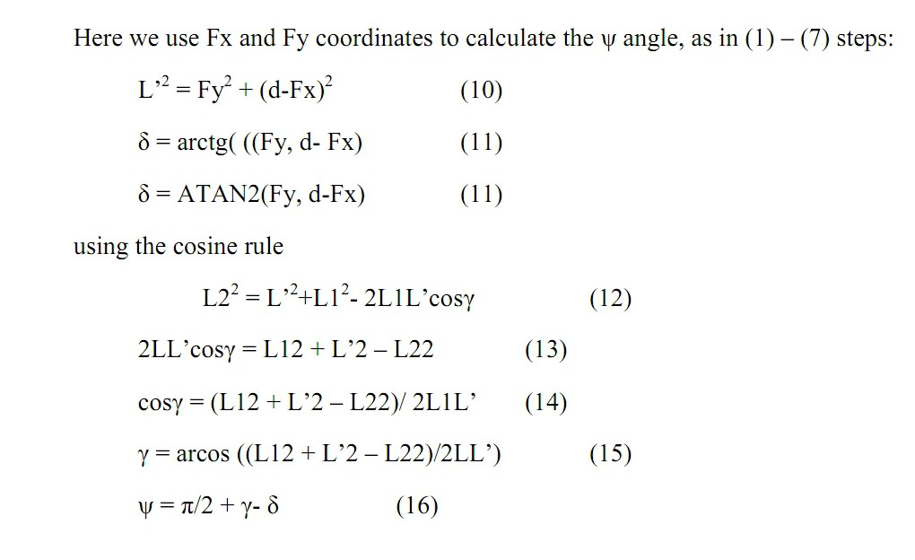
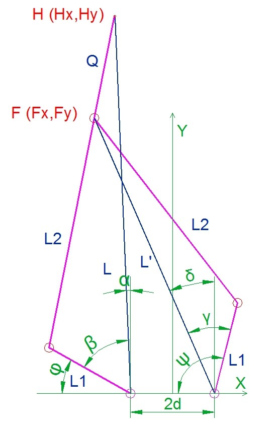
Мathematical formulas for calculating the mechanism
04/12/2018 at 13:00 • 0 commentsUsing the Figures from Log1, we can calculate the angles we need to set a targen point
![]()
![]()
-
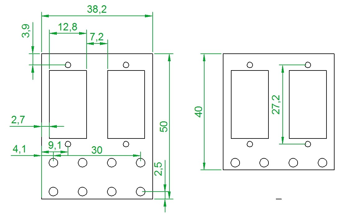
Design of an Five Link Mechanism Levers and Holders
04/12/2018 at 12:44 • 0 commentsWe construct and design the levers and holders for a Five Link Mechanism
![]()
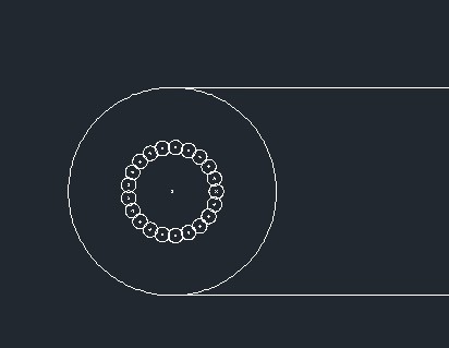
The most difficult is design of a hole for servo shaft. We made it by drilling of some amount of 0.8 mm diameter holes. We use servo s9g. The shaft of s9g is 20-tooth gearwheel. We drill 21 hole of diameter 0.8 mm, the radius of the guide circle is 1.87 mm. Here You can see![]()
If You have other than s9g servos, You have to rearrange the 21-hole figure.
And we made servo holders![]()
-
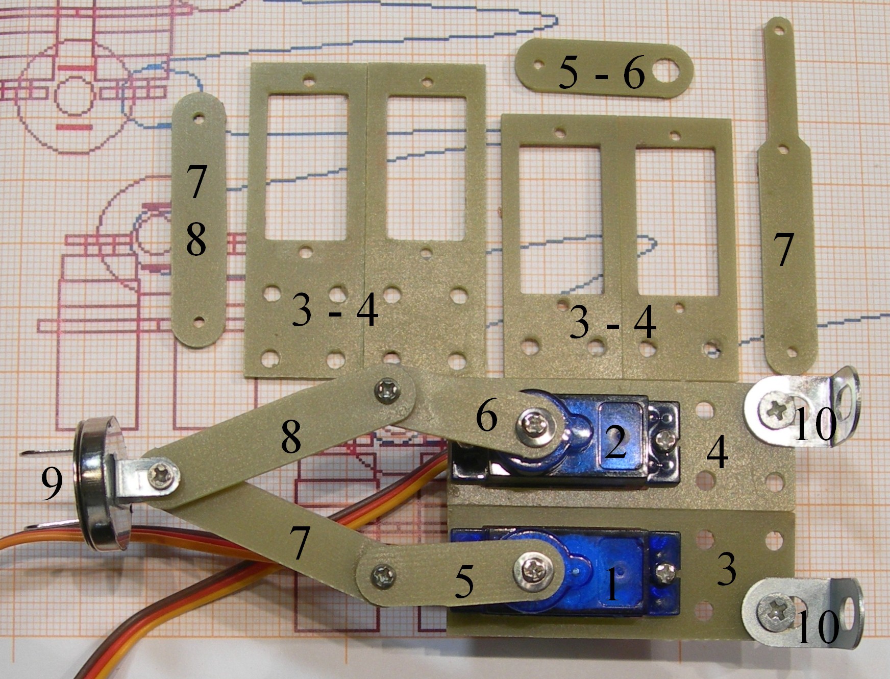
Proposition Of real Mechanism
03/26/2018 at 22:09 • 0 commentsWe make some simple model to test the math.
1, 2 – Servo S9G
3,4 – Servo brackets
5,6 – Low levers of FLM
7,8 – Upper levers of FLM
9 - Central hinge with pusher.
10,11 – Servo brackets holders
And the example of upper lever with Q=20, number 7 right up.
![]()
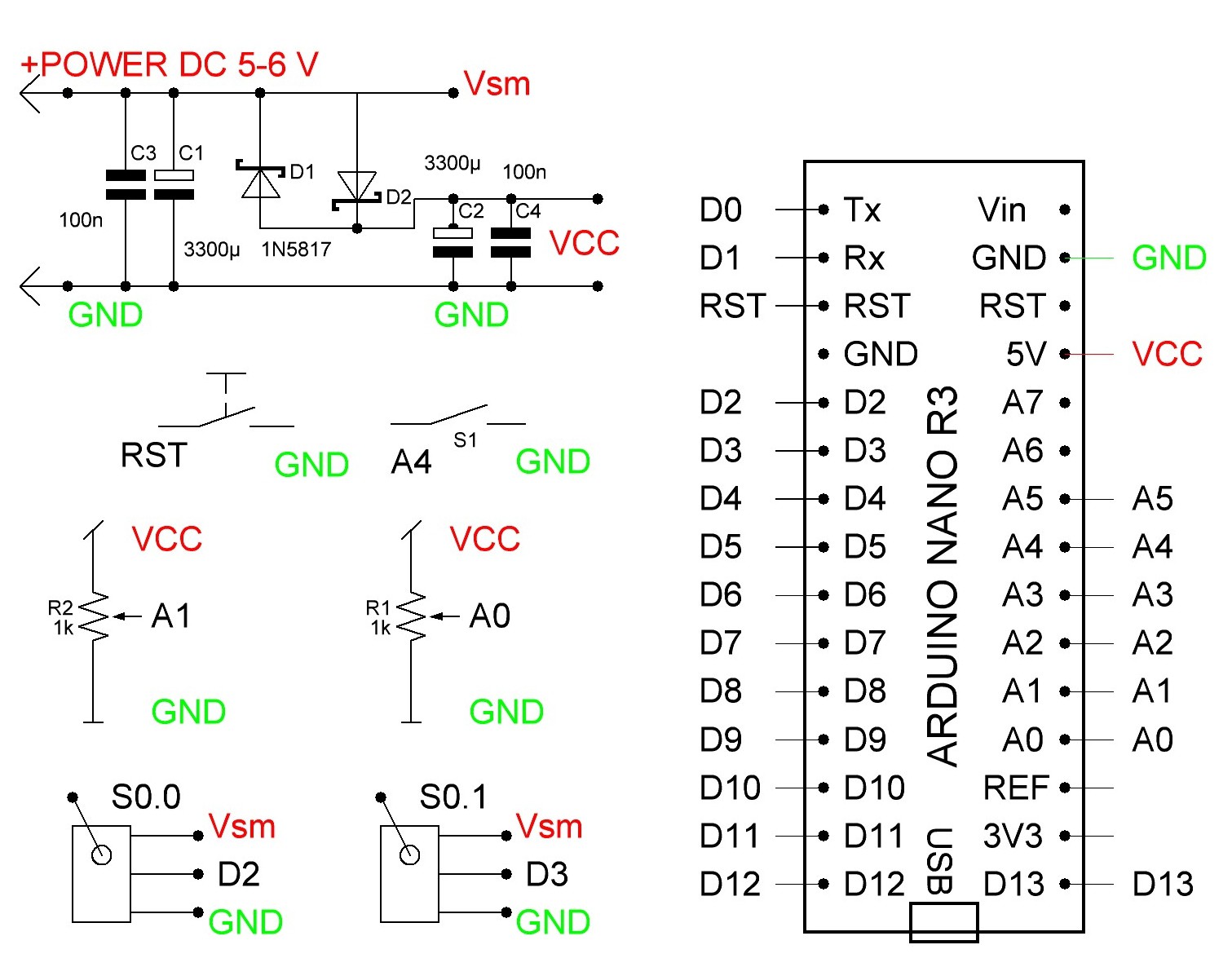
And the schematics for two servo and two potentiometers. See the program code for Arduino in "files".
![]()
-
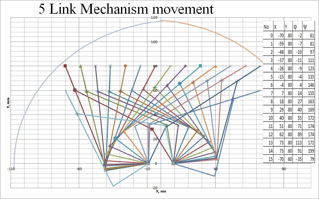
Design of Five Link Mechanism- mathematics model
03/25/2018 at 16:10 • 0 commentsWe calculated the Mathematical Model of a Five Link Mechanism.
We can now calculate the angles of servo drives to readh the target point.
![]()
We can calculate now the track from angles as arguments and the angles as functions of target point coordinates. Here is an example of calculations.![]()
Five Link Mechanism
Five- Link Mechanism is controlled by two servos and make arbitraty 2D movement.