Tobias
-
Correct Signals on the Oscilloscope
04/15/2016 at 00:25 • 0 comments![]()
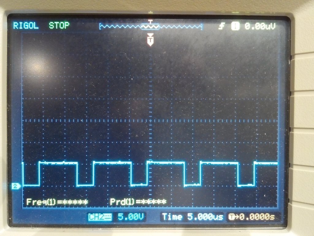
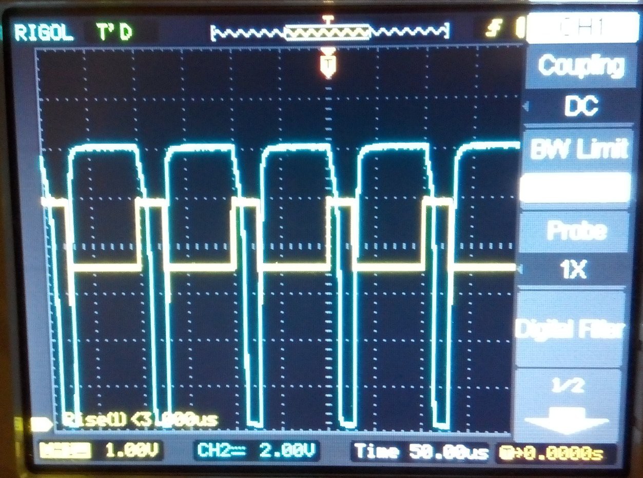
Here are some screenshots of what the signals at different test points look like. This can be helpful for finding the source of a problem.
IR2104 Pin 2:
![]()
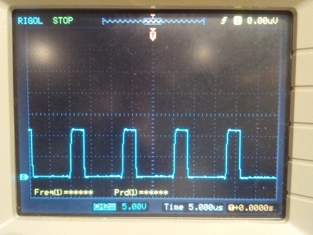
IR2104 Pin 5:
![]()
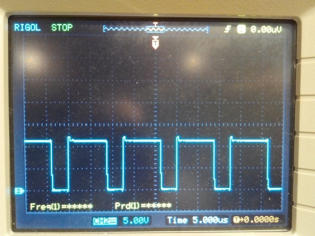
IR2104 Pin 6:
![]()
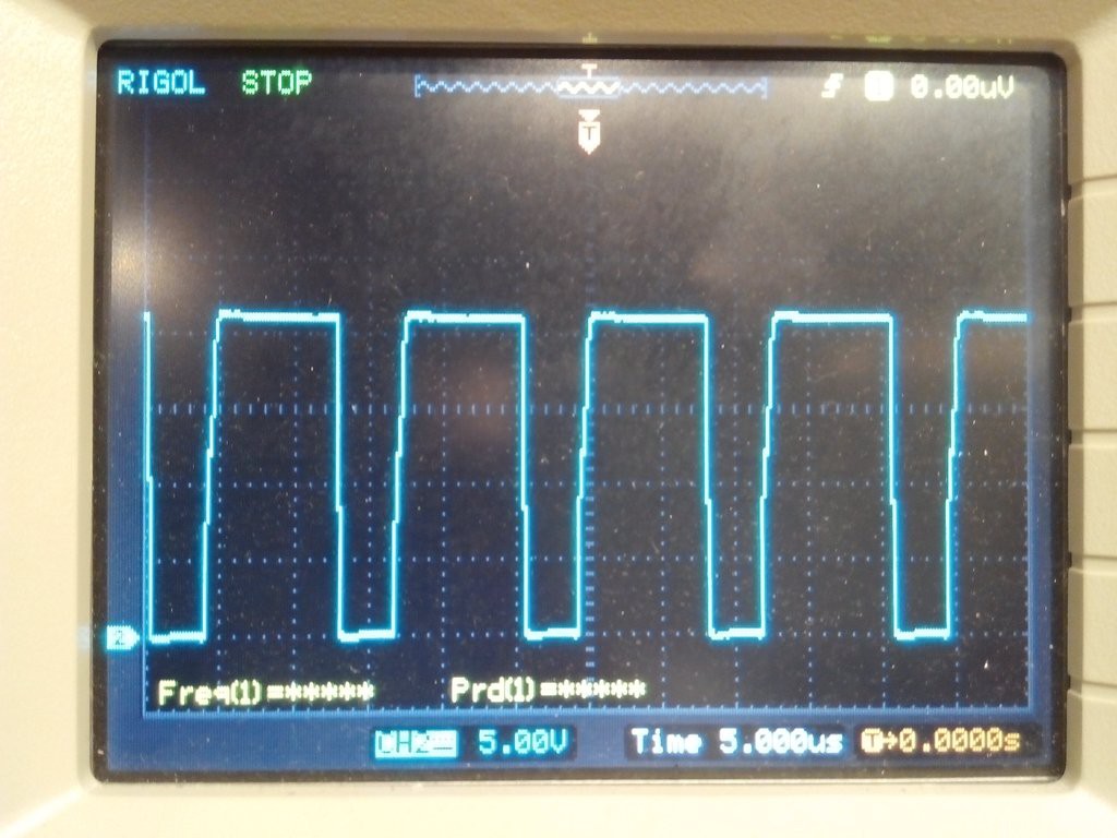
IR2104 Pin 7:
![]()
IR2104 Pin 8:
![]()
Between C3 and R2:
![]()
-
Manual MPPT Solar Charging at Work !
04/08/2016 at 00:26 • 0 comments![]()
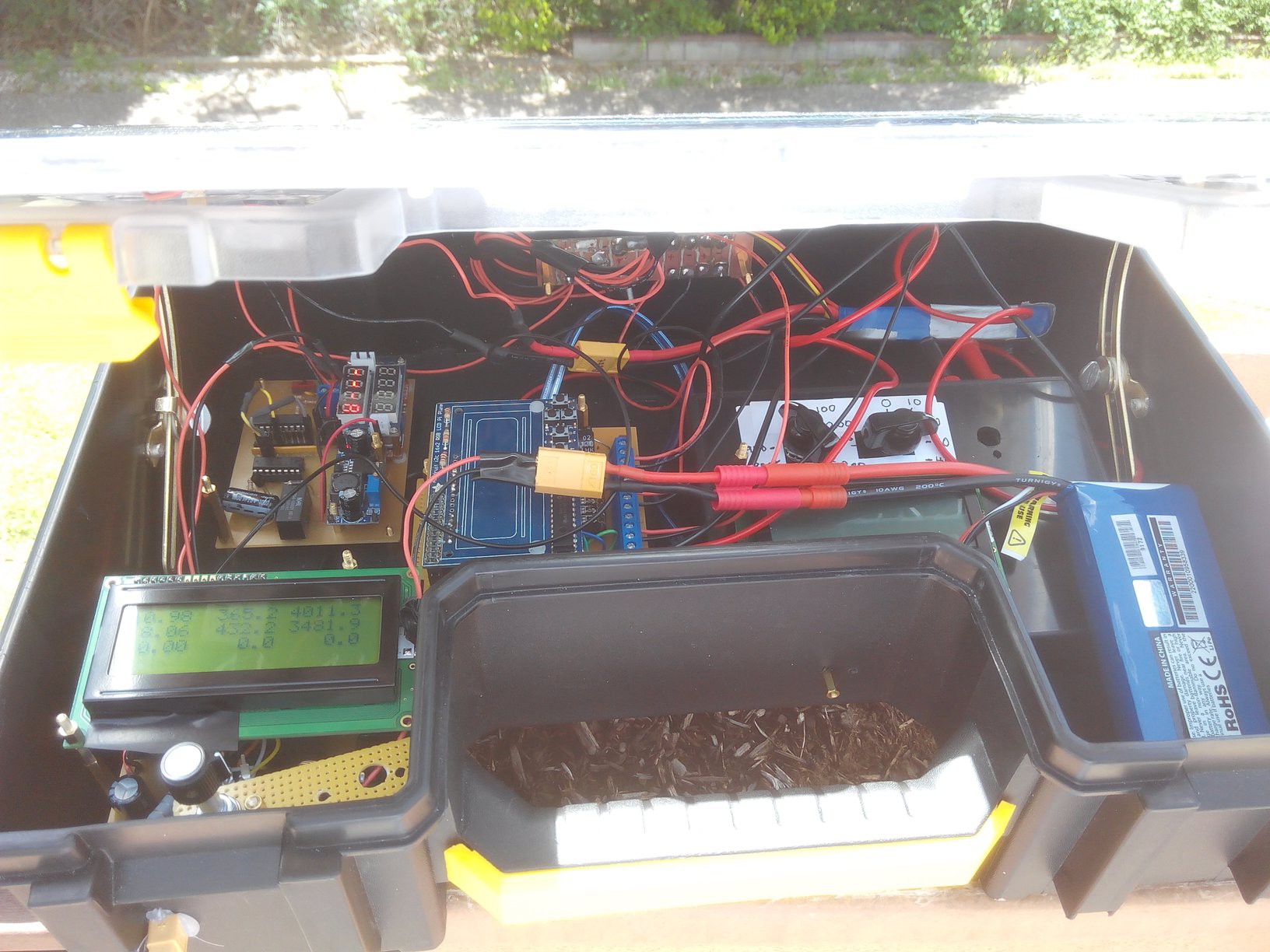
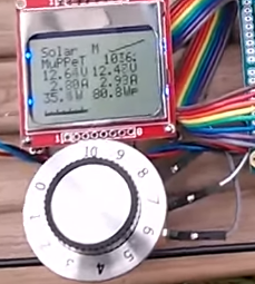
I got pretty good results today. The 4 Watt panel delivered 4 Watts at full sunlight and the battery is being charged at 3.5 Watts, about 88% efficiency.
That is almost a Watt more than the previous solution where I simply placed a Drok buck converter from Amazon between the solar panel and the battery.
MPPT Solar Charger from Buck Converter-Fail
I turned the potentiometer by hand until I found the maximum power. Here is the whole setup:
![]()
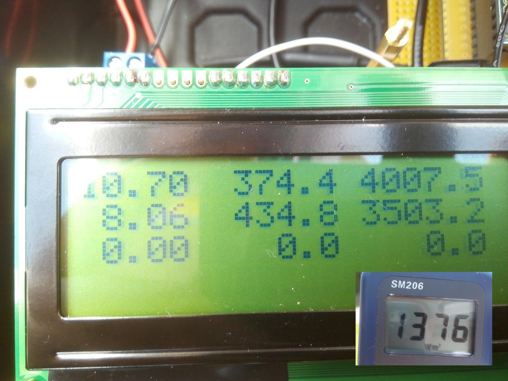
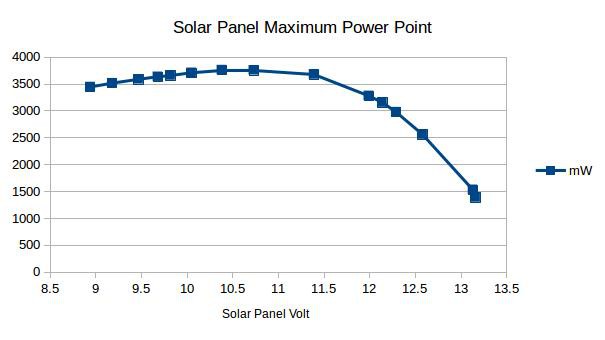
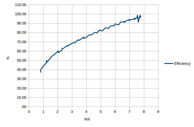
Here is the power curve (a bit later at about 1340 W/m^2)
![]()
A few more tests before I turn over control of the PWM to the Arduino!
-
Things that go wrong, how to fix them
04/04/2016 at 23:05 • 0 comments![]()
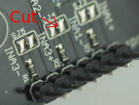
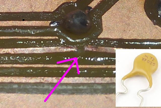
Yesterday, I started getting absurdly high readings on the second INA channel. It turned out that the onboard 0.1 Ohm shunt resistor was broken or disconnected. Fortunately, it is easy to use an external shunt instead. Cut the trace SJ4
![]()
and add a 0.1 Ohm resistor across the load and the supply pin.
![]()
The next board revision should have the shunts external.
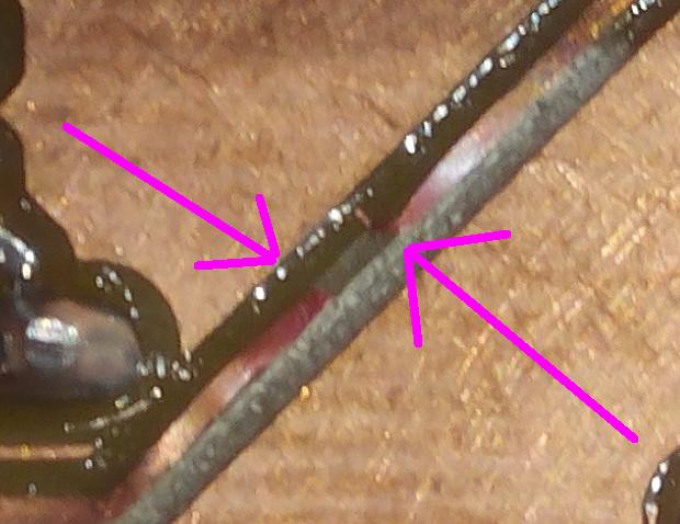
Next, I had a short circuit with smoke coming off the board. Some traces burned off and lifted off the board.
![]()
I think what happened is that when I added the external shunt, I must have cut the wire with the grinder.
![]()
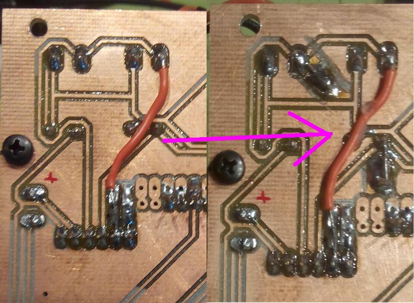
So the red cable that was connected to the battery got punctured and shorted with ground. Remedy: only run additional cables on top off the board. I also added a re-settable fuse to the power control board:
![]()
-
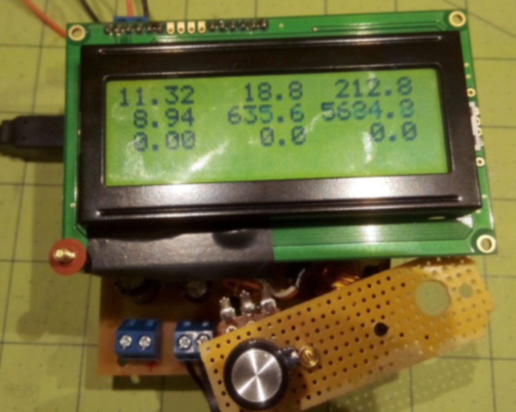
LCD Display and Potentiometer added
04/01/2016 at 01:19 • 0 comments![]()
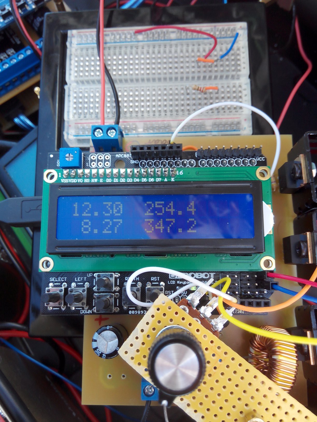
An LCD display was added to display the voltage and current on the input as well as the output. Later, I want to change the shield to an I2C shield and the display to a transflective (sunlight readable) 20 by 4 display so I can also show power, PWM, and efficiency. Also, a potentiometer was added to change the duty cycle of the PWM to conveniently find the maximum power point. It's a good step to test the system before letting the Arduino control the PWM. Credits to Julian Ilett for the idea.
![]()
-
Efficiency of Buck Converter
04/01/2016 at 01:08 • 0 comments![]()
A test of the efficiency of the circuit with an input voltage of 10.5 Volts and a load resistor of 10 Ohms shows that in the high duty-cycle region of the PWM signal, the efficiency is over 90%.
-
Arduino MPPT History
03/31/2016 at 23:44 • 0 commentsAs far as I know, Tim Nolan started the Arduino-based MPPT solar charge controller design in 2009:
![]()
Unfortunately, his web site is down
but the content can still be seen at
In 2013, Julian Ilett created a circuit that uses only one n-channel MOSFET instead of three, using opto-isolators to transfer the PWM signal from the Arduino to the MOSFET.
![]()
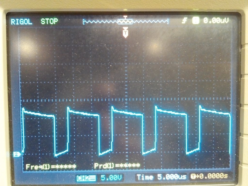
I tried this approach but didn't like the frequency response of the opto-isolators:
![]()
Already at 15kHz, the rectangle pulse is degraded significantly, so I opted for the driver-based half-bridge solution (currently running at 80 kHz).
There are lots more of Arduino-based MPPT's but these are the ones that I have used in my project.
Arduino MPPT Solar Charge Controller
The charge controller consists of a buck converter that is controlled by an Arduino via a half-bridge driver.