I myself got quite deep in my last job, so everything got put up aside-ish, but no more, as they had to fire me due to external factors to the company.
So, meanwhile I get a new job, I will be able to put all the files in a more comprehensible format/shape, and look for better ways to make all the info avaliable.
Also, i will post again about news and such, as I think I found a cheap-ish way to do a wirebonder, and sources for hotplates that make it not worth to build one yourself.
More info soon!
Btw, if you happen to share the patreon link on twitter or something, thanks in advance and let me know!
On my side, finally foubd a job wich i enjoy AND pays well. XD
I also have been finishing the curve tracer, located a possible source for low concentration HF, and bought a few more vidicon tubes for the e-beam gun, so I have spares to break without worrying much.
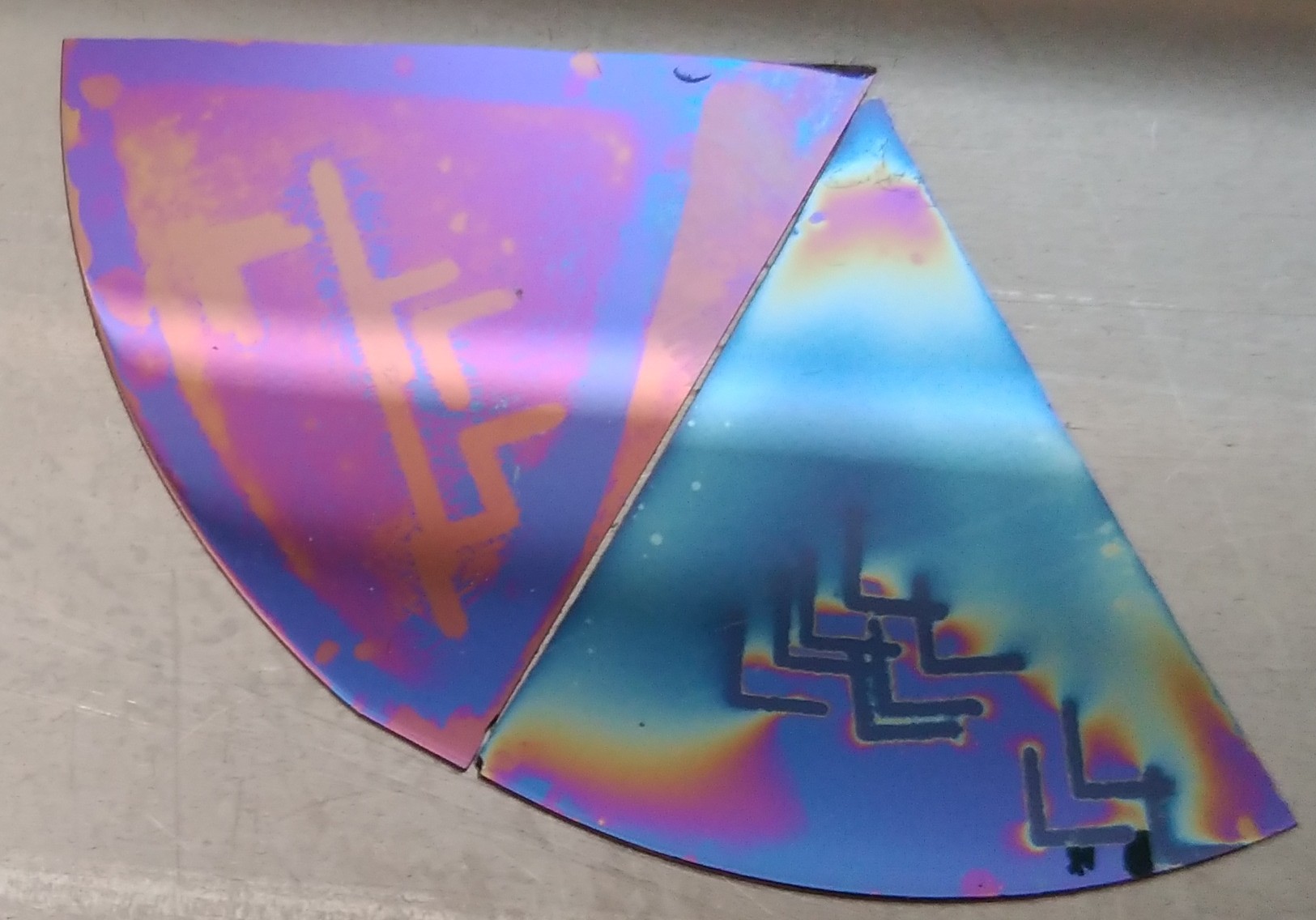
First noticeable diode effect in N-type (phosphor) wafer, using Boron.
Right now I'm stuck with N-type (Sulphur) doped wafers, so I'm using boric acid as boron source. When cooking it, it produces borosilicate glass on top of the wafer, wich, if you use too much of the dopant, makes for such a thick film that can't be really etched away. Luckily, a small window opened in the center of the test, and I could access the boron doped part. ^^ (after diffusion, before etching)
Also, laser paterning is coming along nicely! 2mm test square and "+" fiducial. Should have left in HF longer, but curiosity got the best of me. ^^
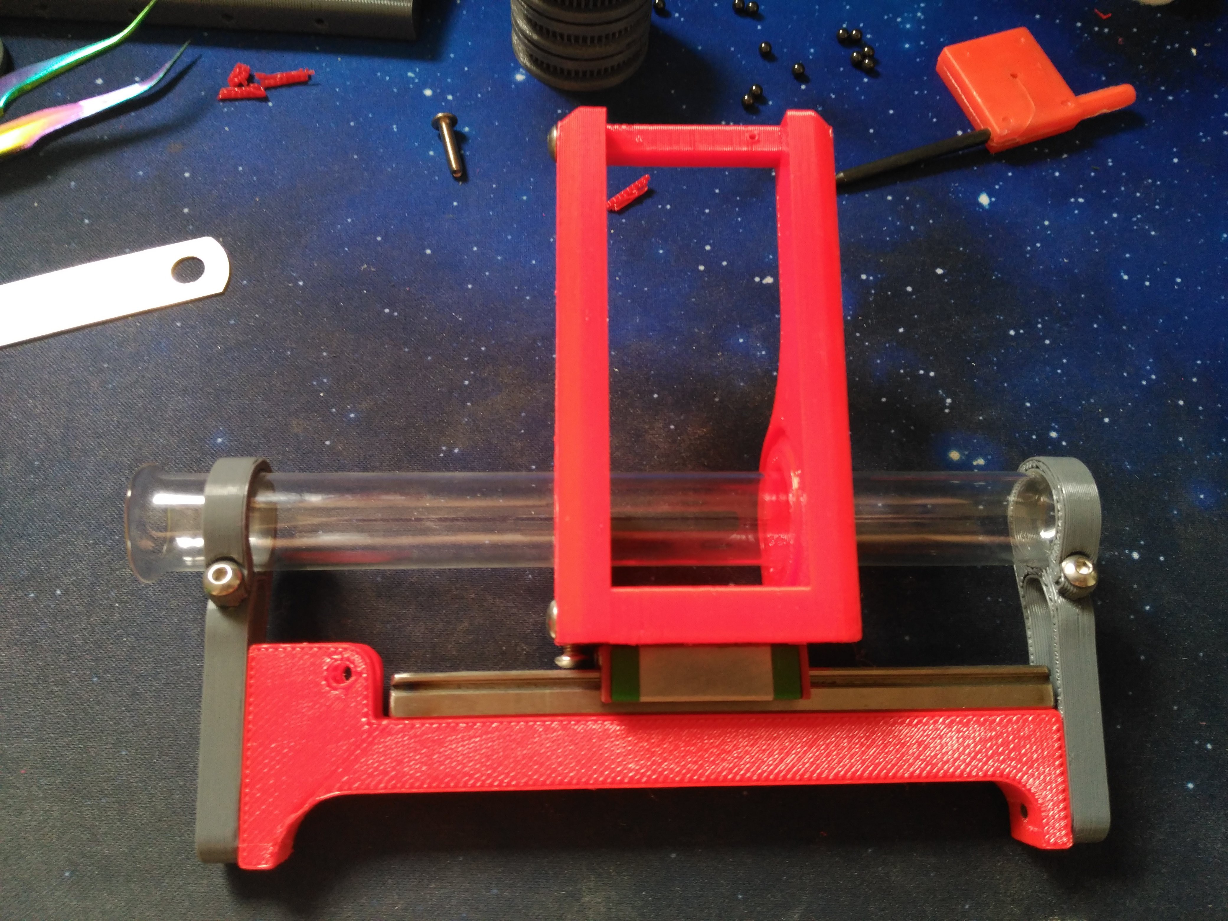
When we left, this was the general idea I wanted to achieve:
A magnetic HVAC interface using a (modified) glass test tube for vacuum holding.
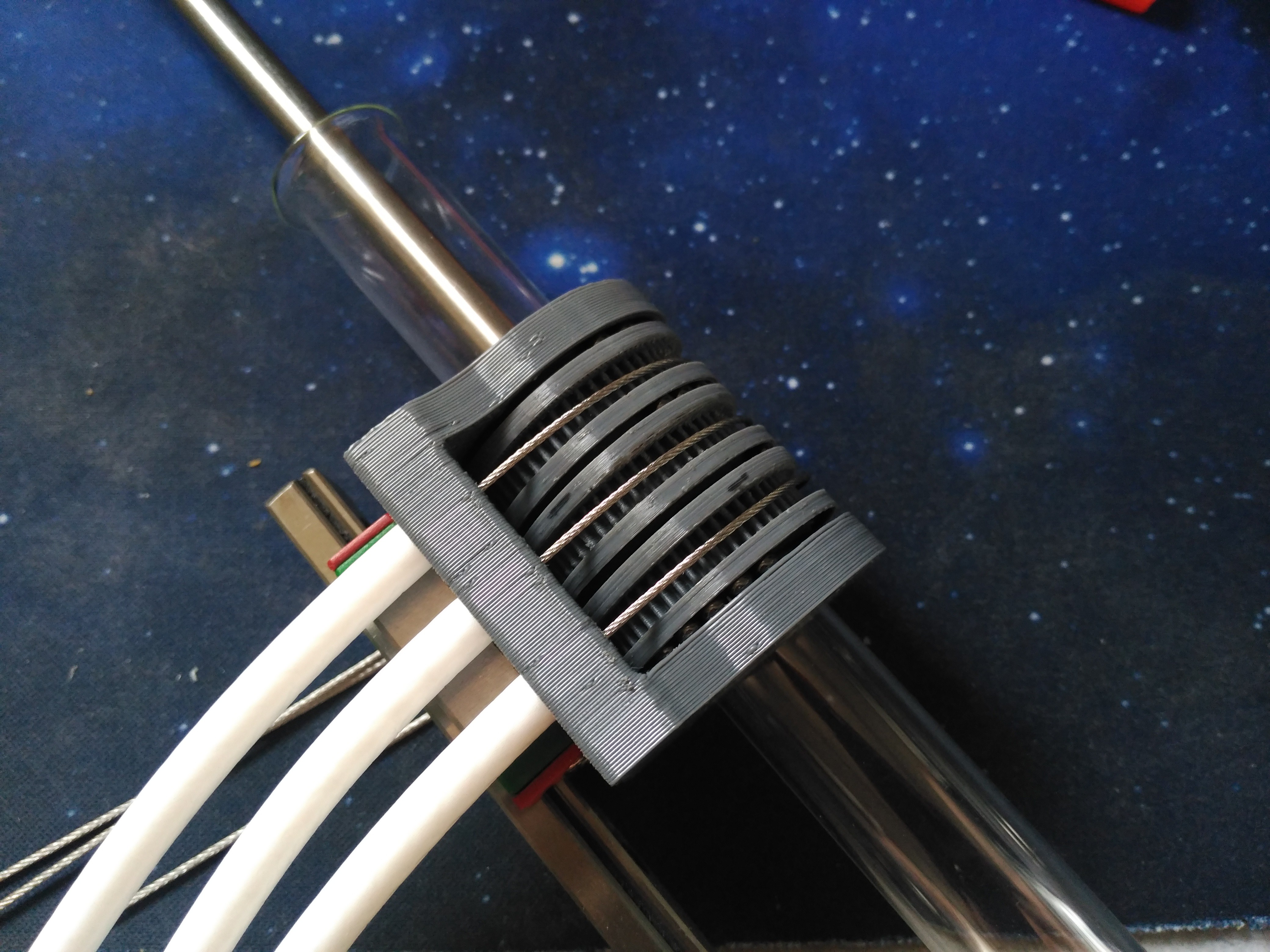
First thing I adressed was the driver holder/actuator. Gear/rack mechanical coupling proved impractical, so I switched to bowden drive:
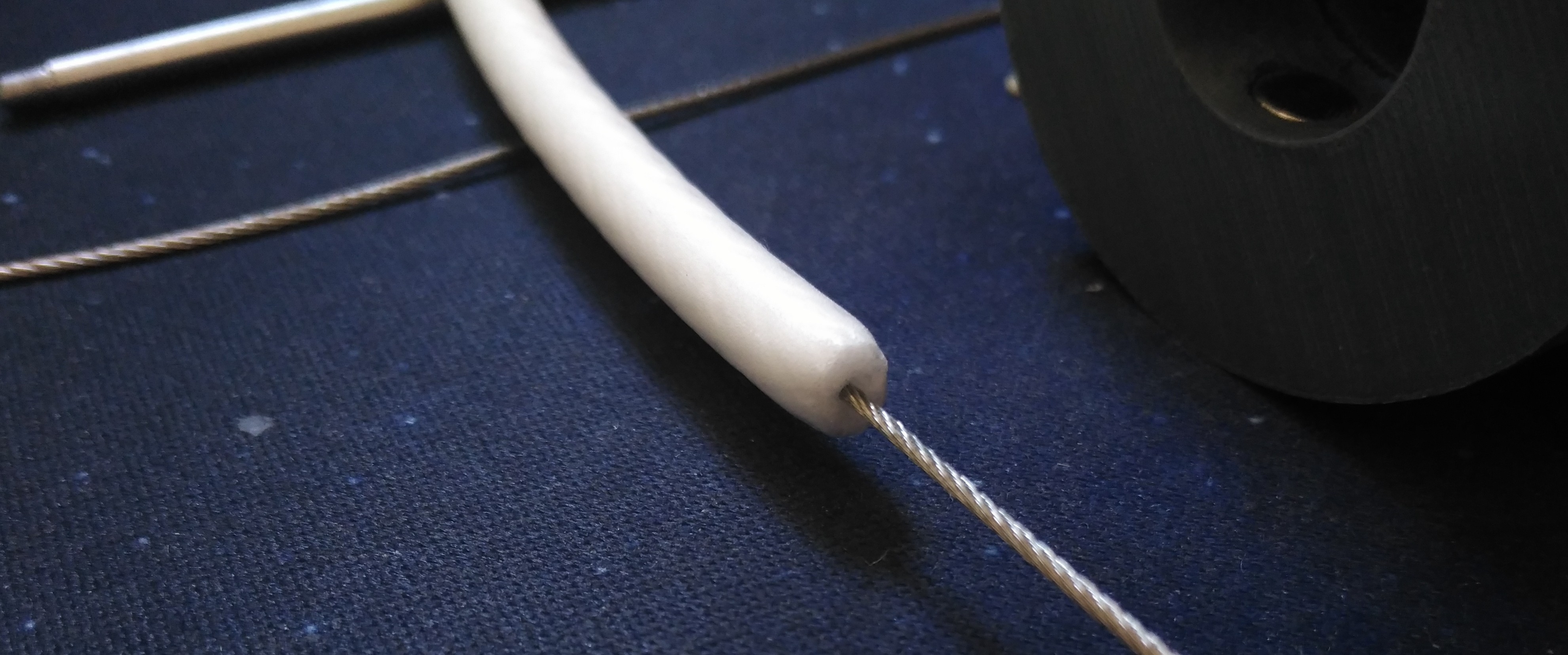
I had thin braided steel cable in my workshop, for pneumatically pulling things in other projects. What I did not have was bowden tube of any kind!
Coaxial cable, help me!
UHF cable core is usually made either of poliethilene foam or, in higher grades, from PTFE. I wasn't as lucky as the second choice, but for short distances and small forces, PU foam would work fine. (for future projects I did order PTFE tubes)
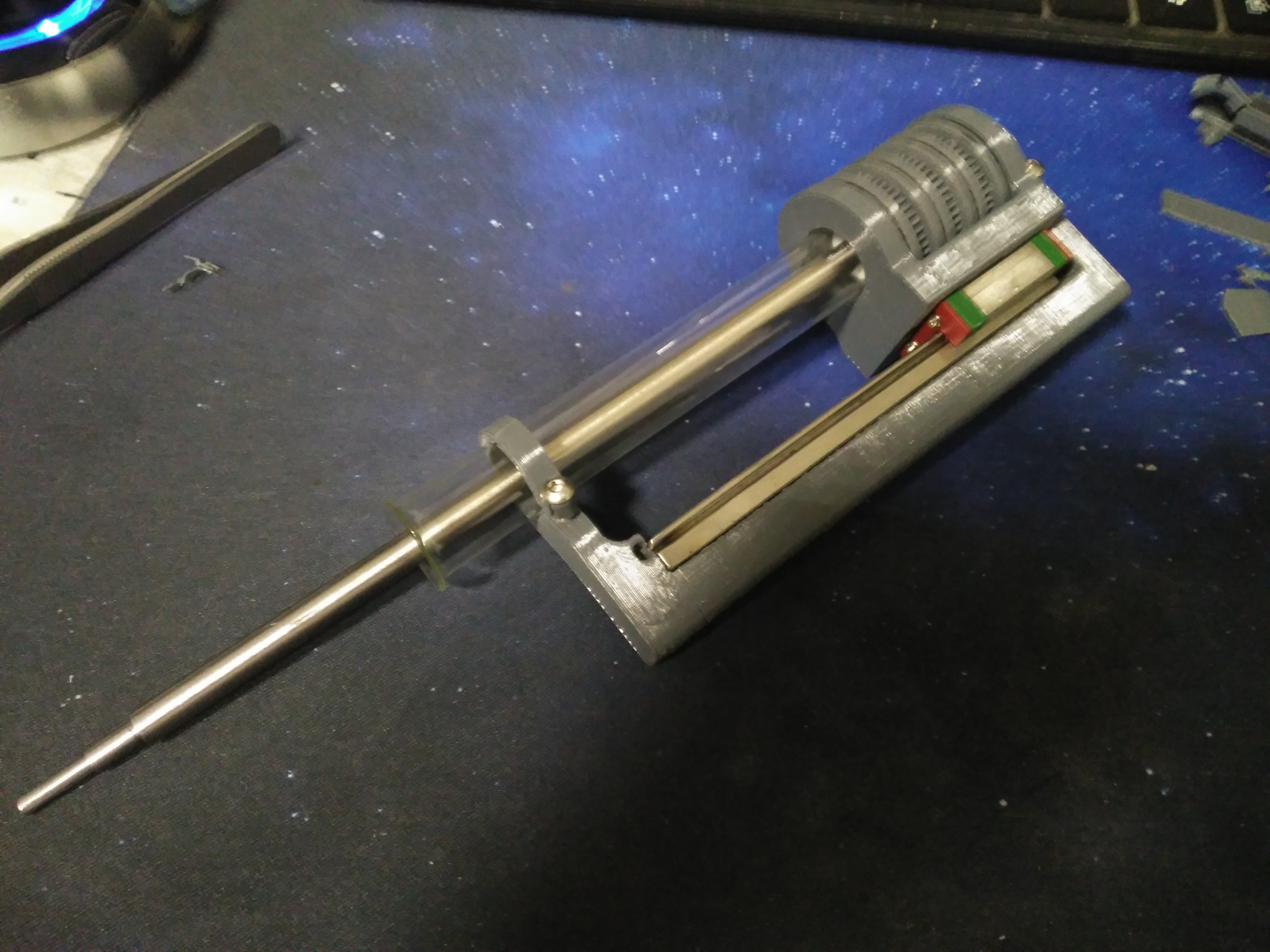
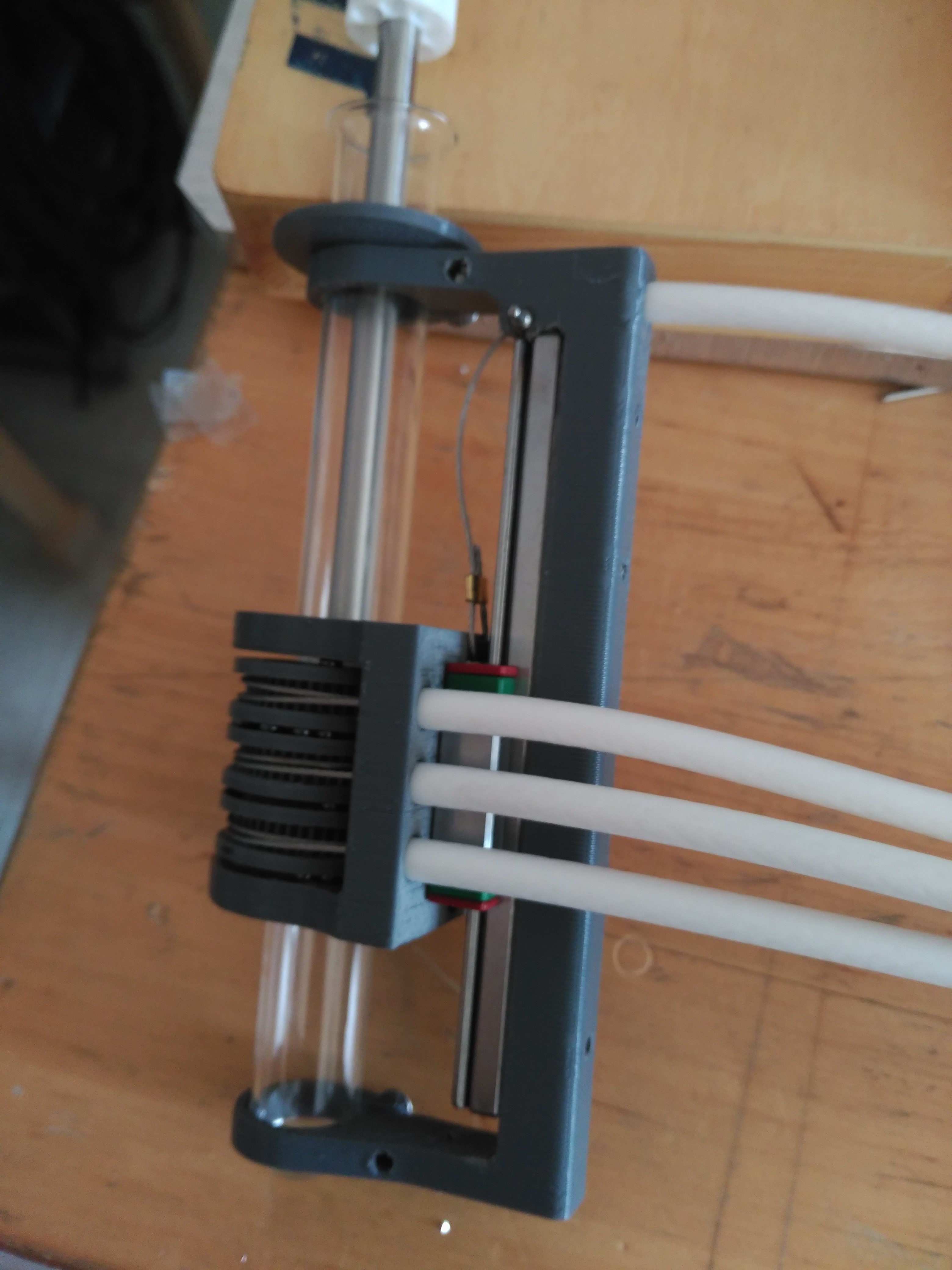
A linear rail was added to the back to attach the motion driver to the test tube and provide Z axis movement/control.
Wich would also be bowden controlled:
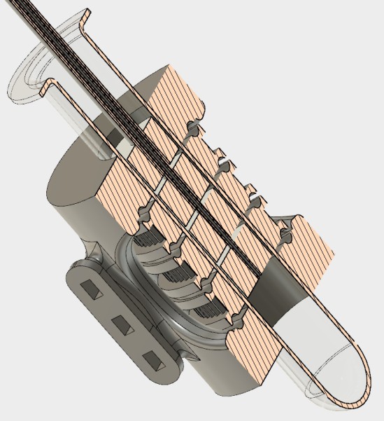
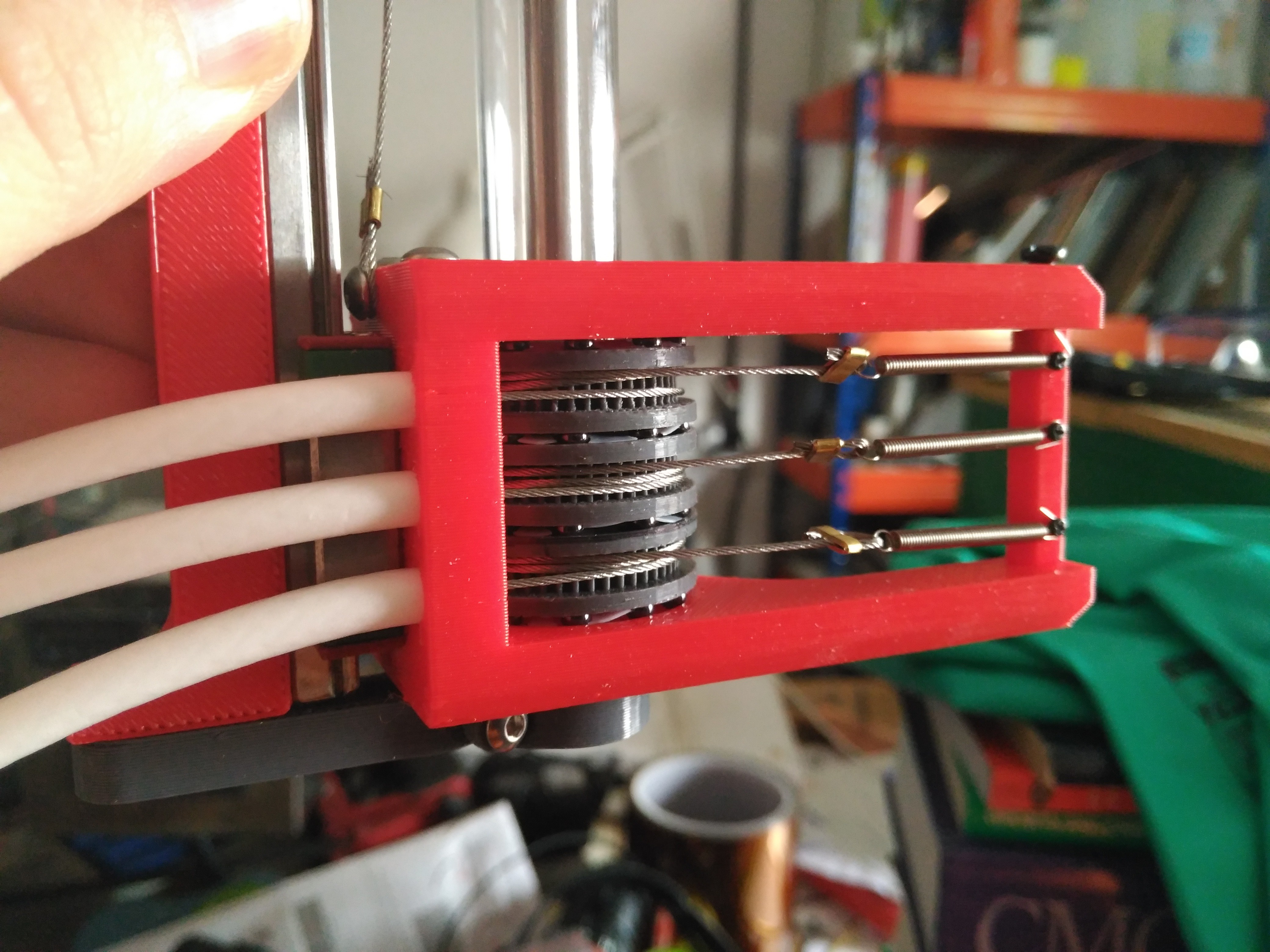
Springs on the other side of the bowdens would provide cable tension. However, altough the bearings could take it, they exerted much lateral force in the pulleys, binding the rotary motion, so, a second version with zero radial net force was implemented.
The axis of the push/pull force in the cable sit in the same plane, nullifying the force exerted on the pulley (technically, it generates a twisting motion as the cable does not alignt with itself, but the bearings can cope with that easily)
Also, the fixed test tube holder didn't really work, as each test tube is slightly different, so, the linear guide holder was made as separate pieces, making the tube supports adjustable.
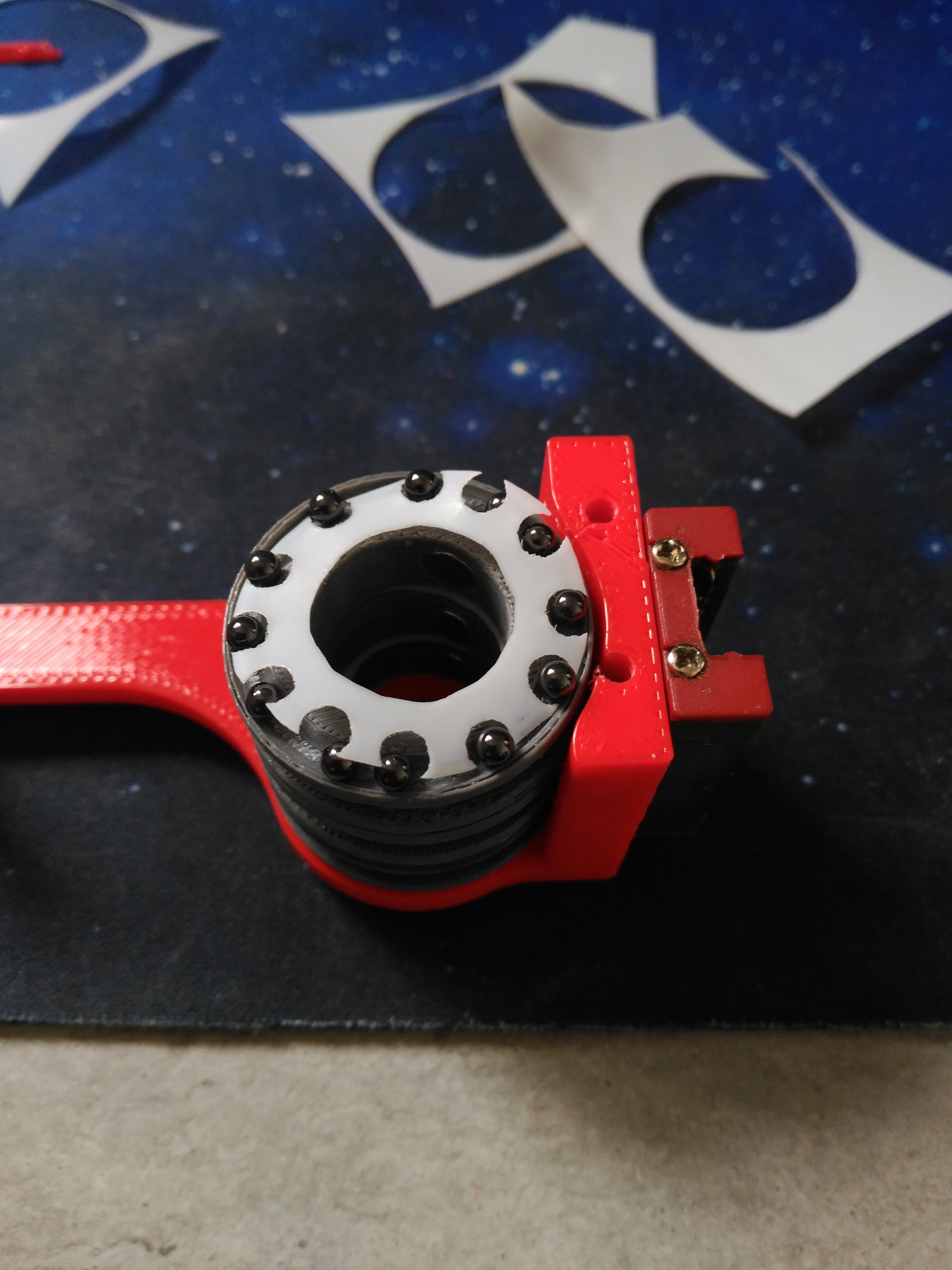
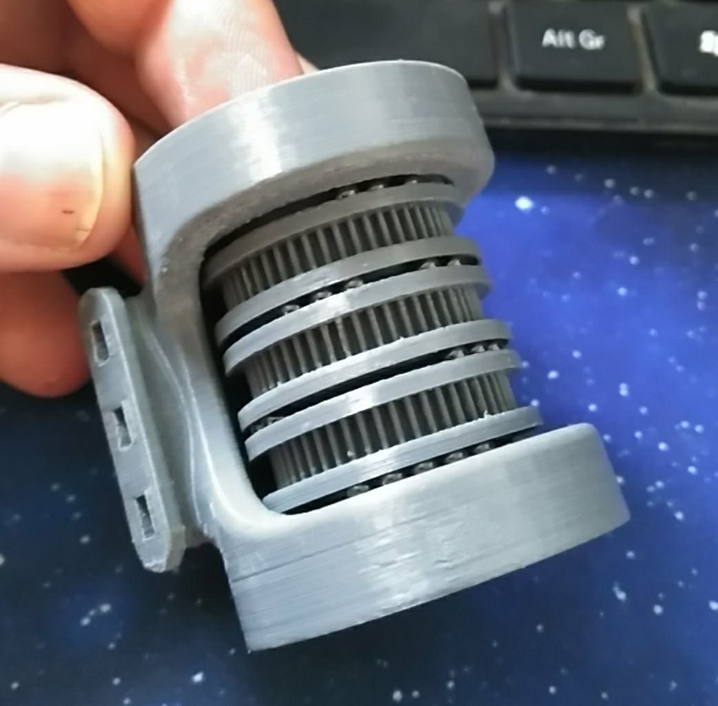
Teflon ball cages where scissor cut so the balls would sit properly in the pulleys:
Small sections of brass tube would be flat clamped to the cable to make connections.
In action:
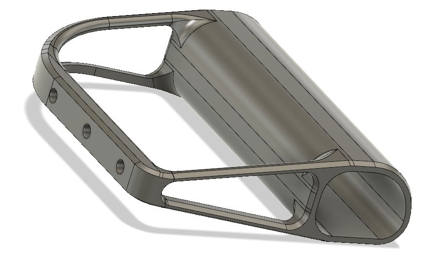
After that, it was time to make a hand controller for it. So I mostly went nuts with the chamfer tool in fusion 360:
That hand piece would get attached to a linear rail with an adaptor, wich in turn would be directly screwed to the sputtering table.
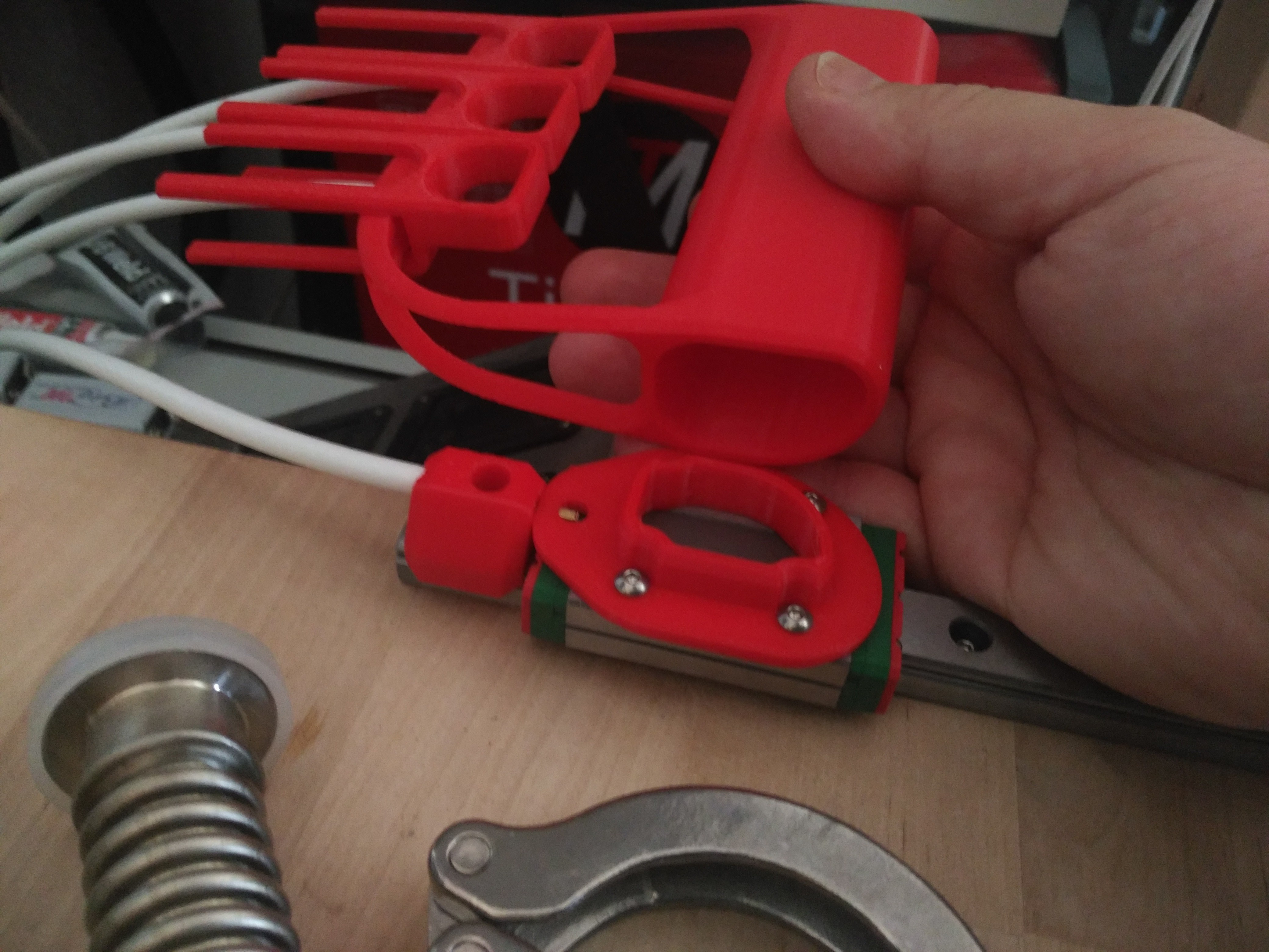
The whole hand will move the Z axis, whereas each finger will have direct control of one of the pulleys with these finger cable pullers:
And how does it work?
AMAZING, if I can say so:
Here's a bottom view of the assembly coupled to the vacuum chamber:
All the bowdens where cut to the minimal lenght and lubed with silicone oil. For upper guidance/parallelism a PTFE guide for the metal parts was cnc cut:
So what does all this accomplish?
I now have a modular system with 3 coaxial axles with Z movement that I can employ for anything inside the vacuum chamber, WHILE it is operating.
I can have different motion groups for different purposes and all I need to do is remove the internal magnet assembly, wich slides out into the chamber, and put a new one, with different end effectors/holders/targets.
Here, for example. I'm spot welding a small strip of stainless, in provision for the small arm that can move samples around:
Instead of an arm, I can use it to put a plate over the samples and cover them until the sputtering is stable and clean.
Or:
I can have one arm with targets, and switch them at my convenience, while a second arm covers the samples meanwhile the changes (leftover sputter of a different material) stabilize.
There are infinite possibilities for this, It is just a matter of what work I need doing inside the vacuum environment.
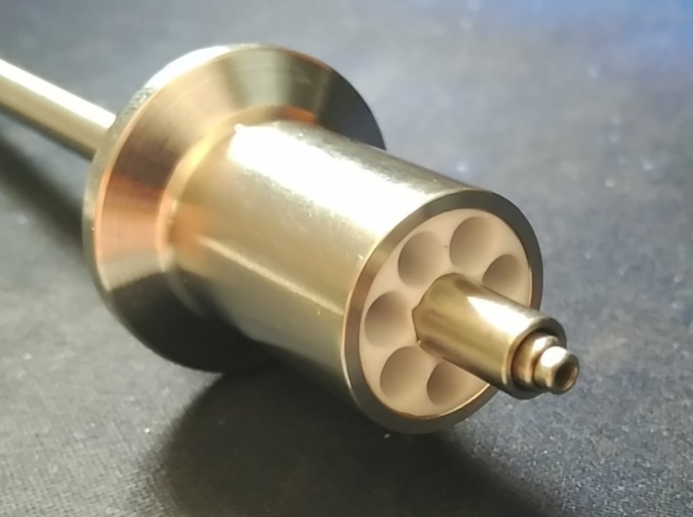
Glass details:
The glass test tube is hand-modified with an Oxy-torch in the lathe, so you can do everything at home, no need to depend on anyone for weird pieces.
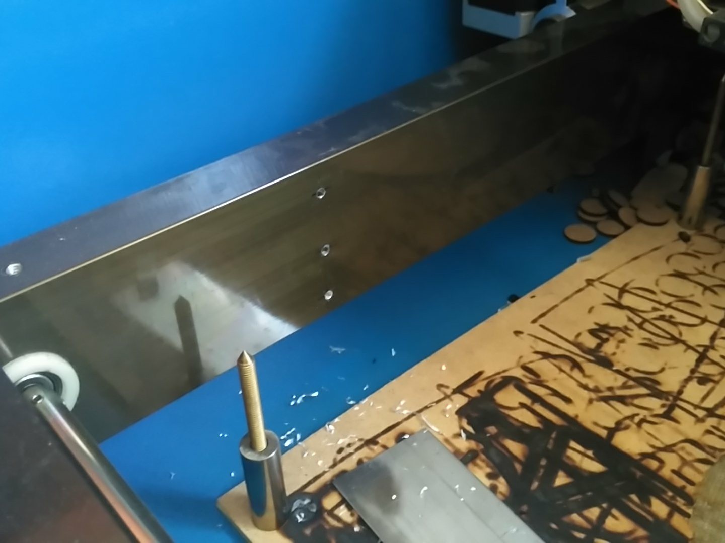
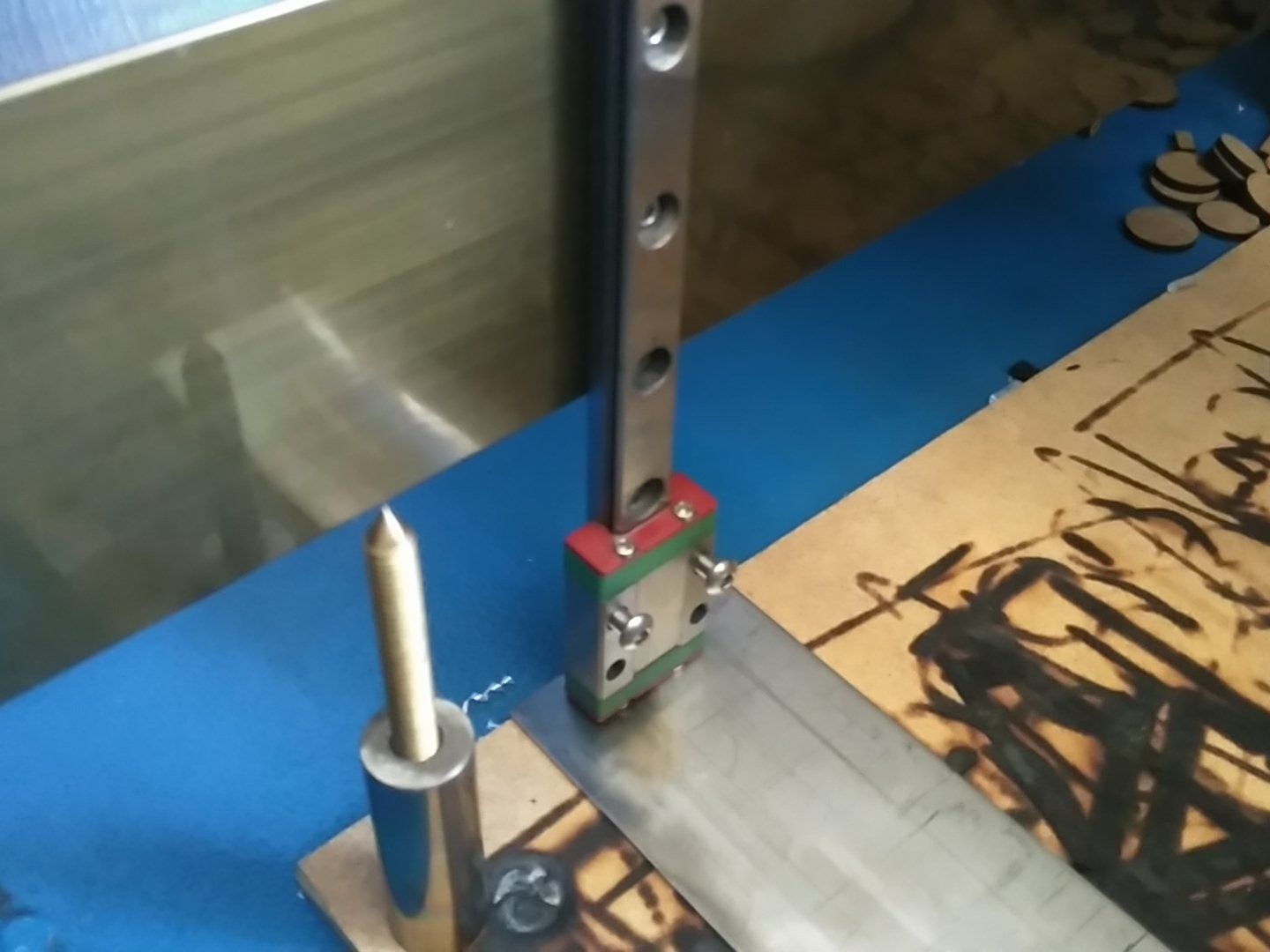
Until now, I had been doing the laser litography tests with the machine as is. Nailing the focal point was tricky, if I ever found it.
Once I started having better results with the technique (right in the above image) it was clear I needed a better way to find and mantain focus with the silicon.
The holder also has to be hollow, since the laser mostly goes through the Silicon, and having a surface just below the wafer, could prove problematic.
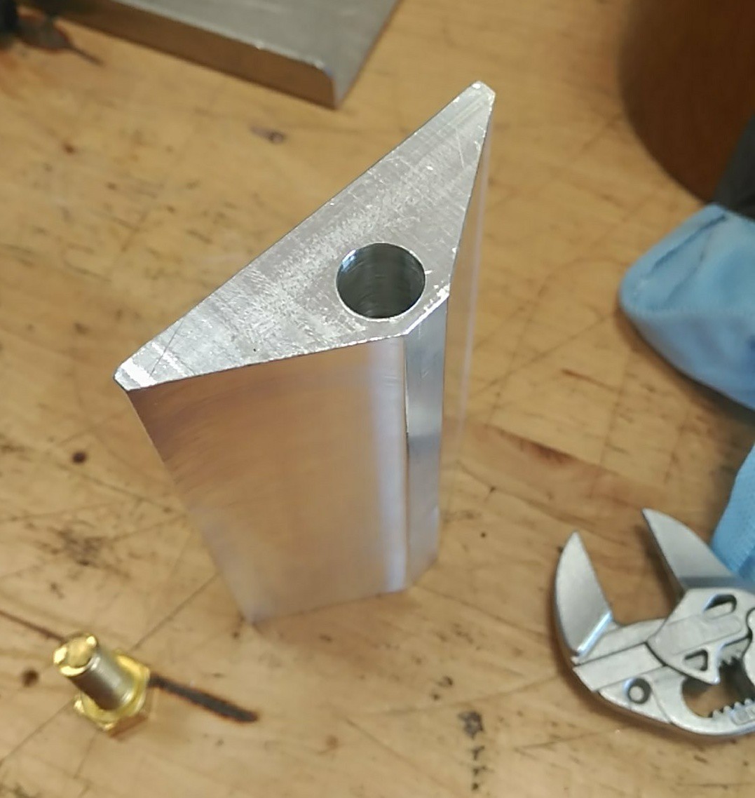
So, holes where drilled...
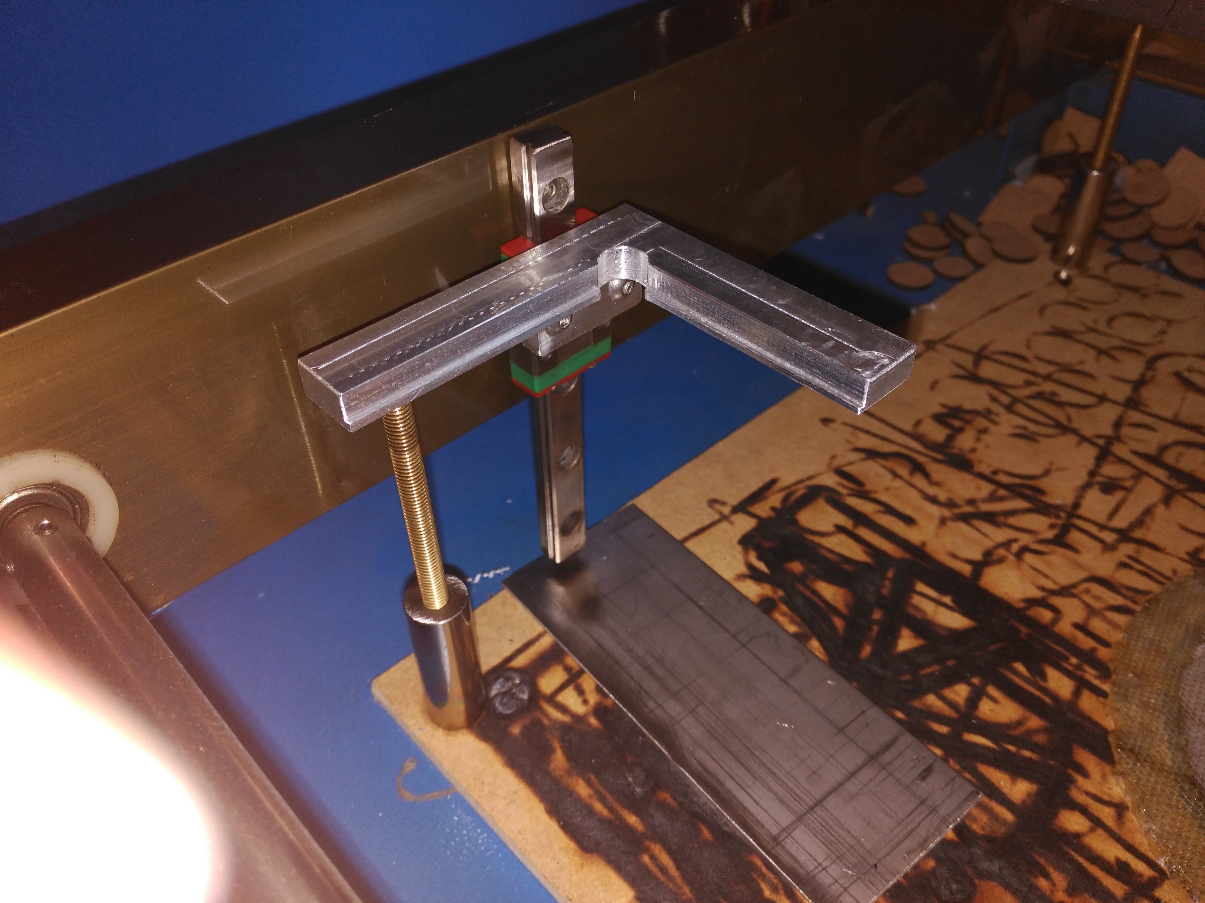
And a vertical linear rail was added:
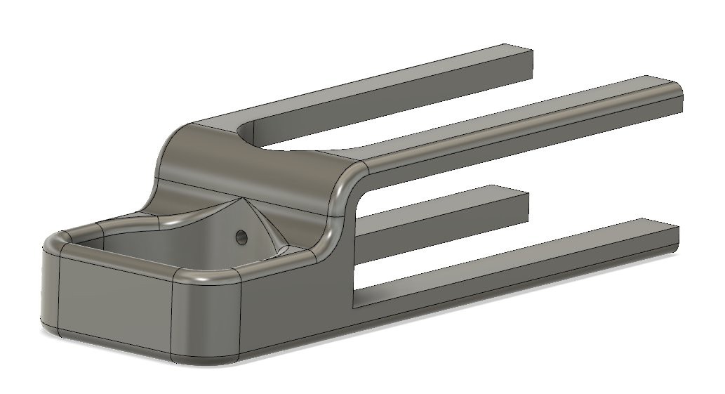
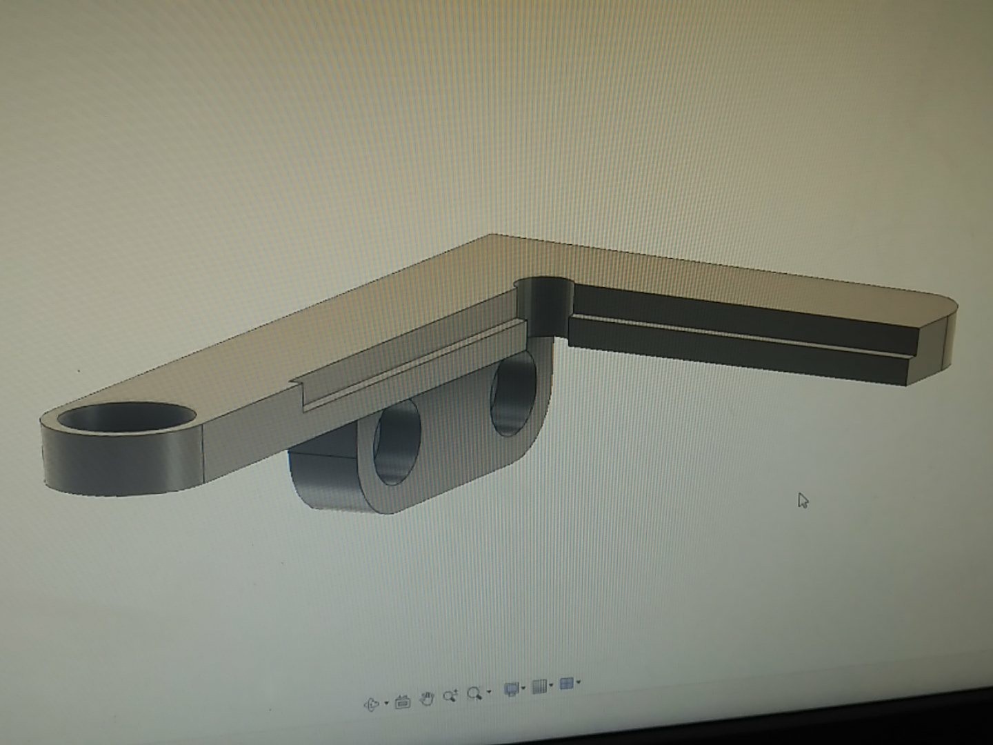
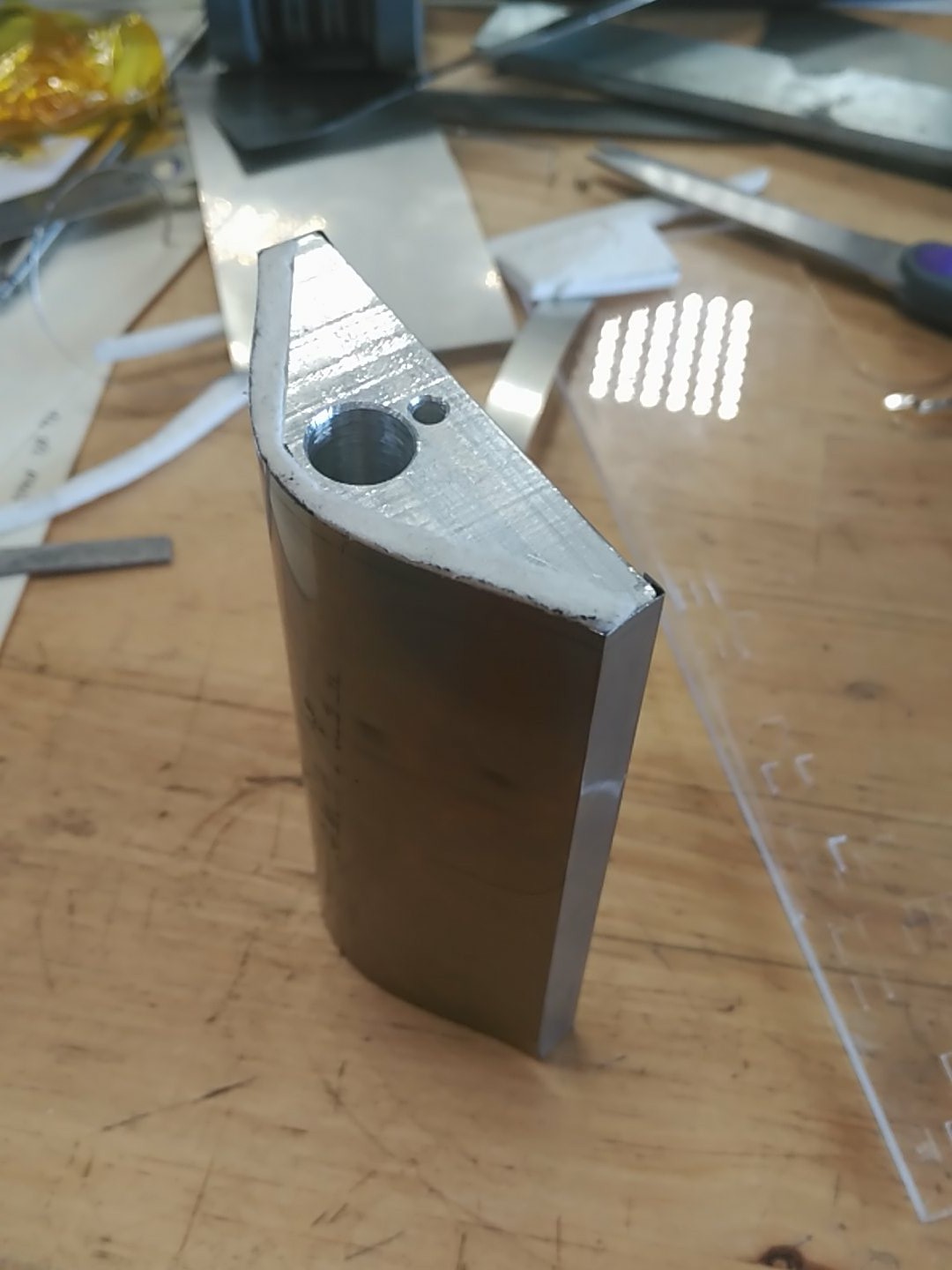
The design requirements dictated the shape, edges and lengths, so there wasn't much to the design:
This piece, working near a laser, should not be made out of plastic, however, for quick tests, I 3D printed it to have a feel of how it sat in the machine. (Just ignore the bearing, it was meant for something else, but it was not needed in the end.)
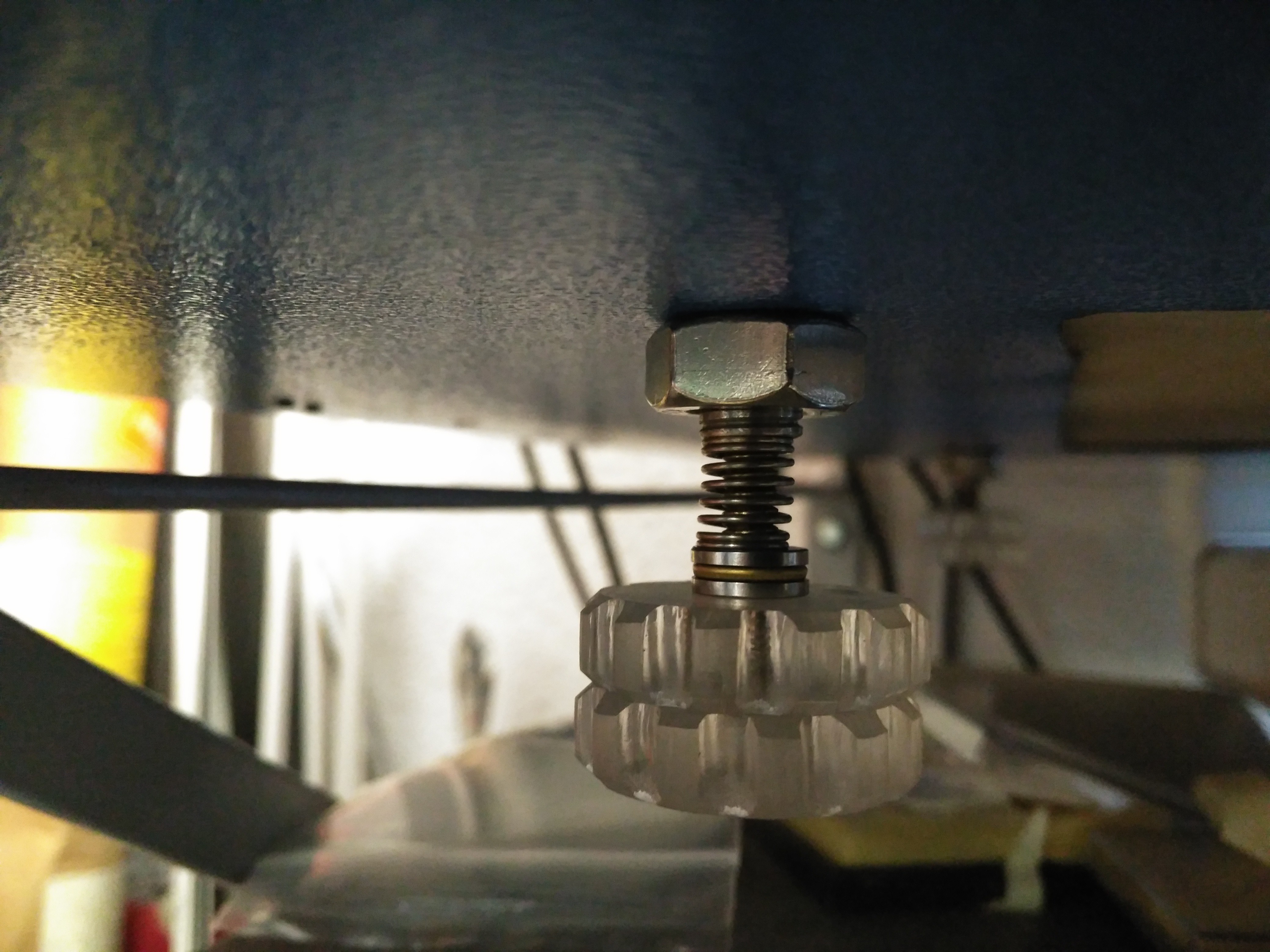
I will be using the cutting height adjusters, however, just as they where, it could probe flimsy for precision height adjustment, so the screw was preloaded with a spring and an axial bearing to prevent twist resistance:
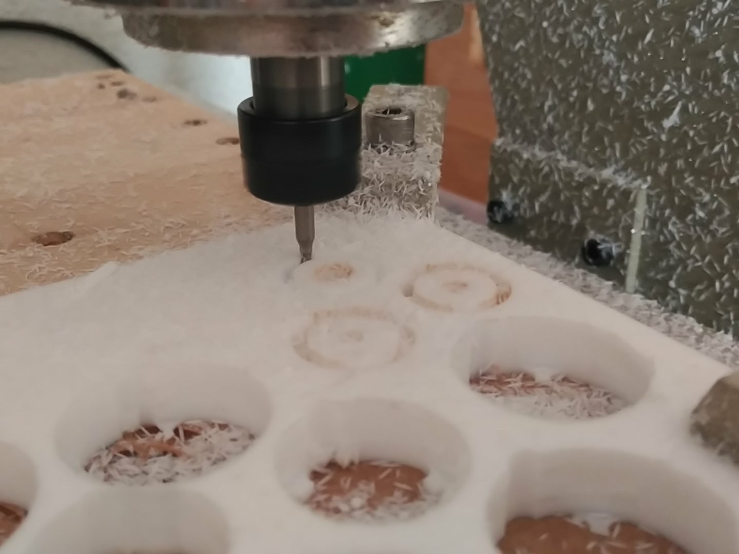
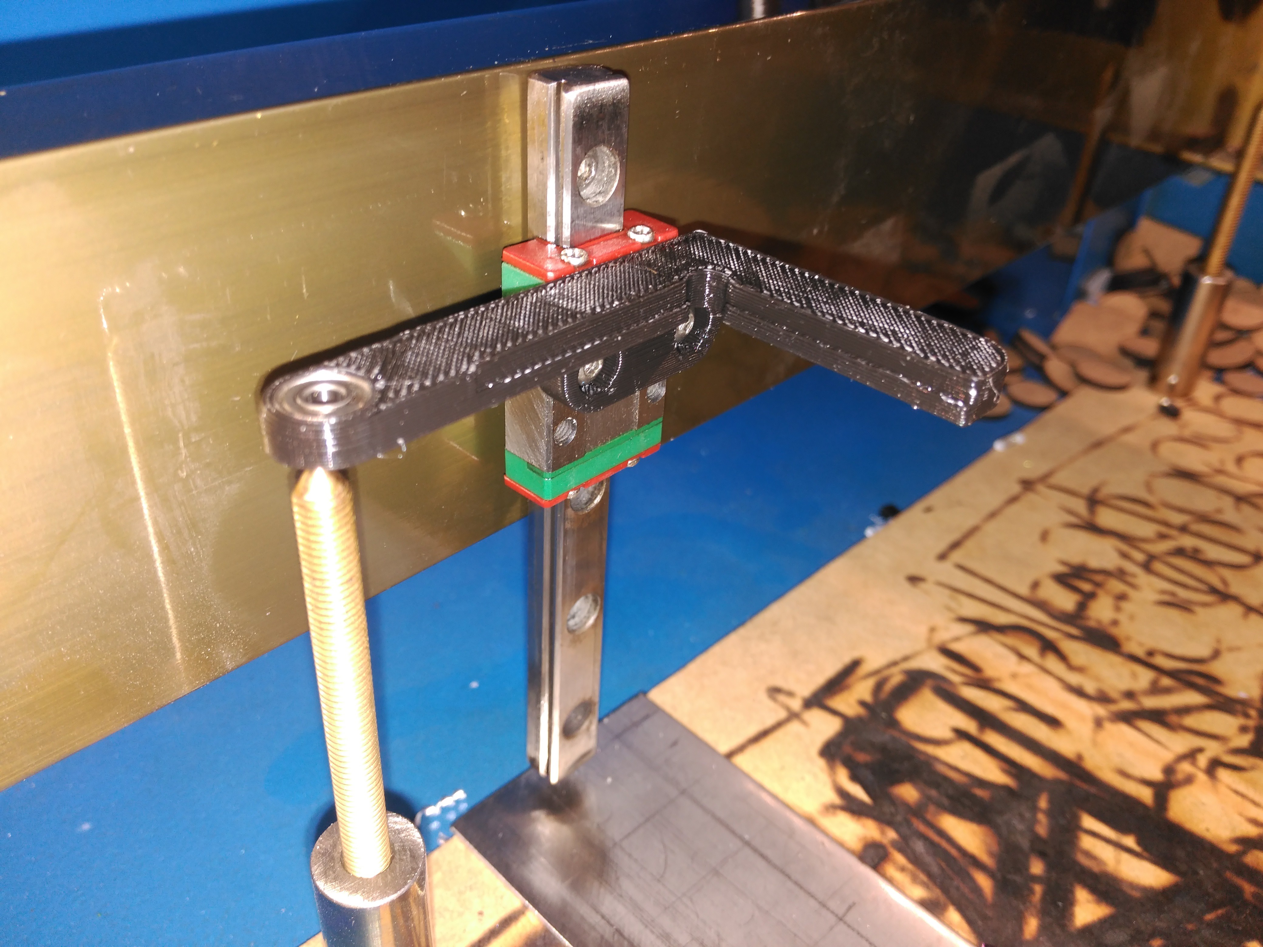
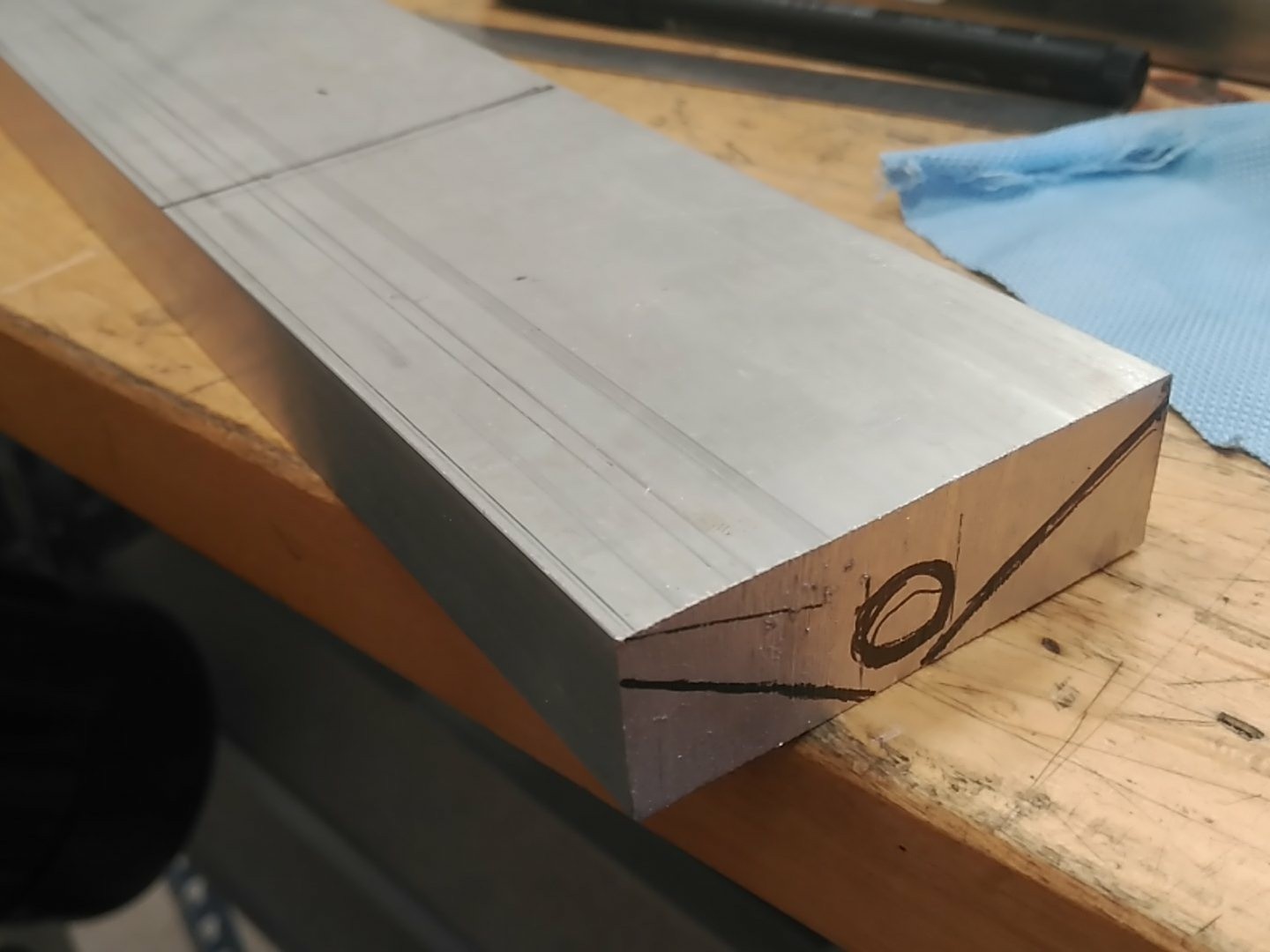
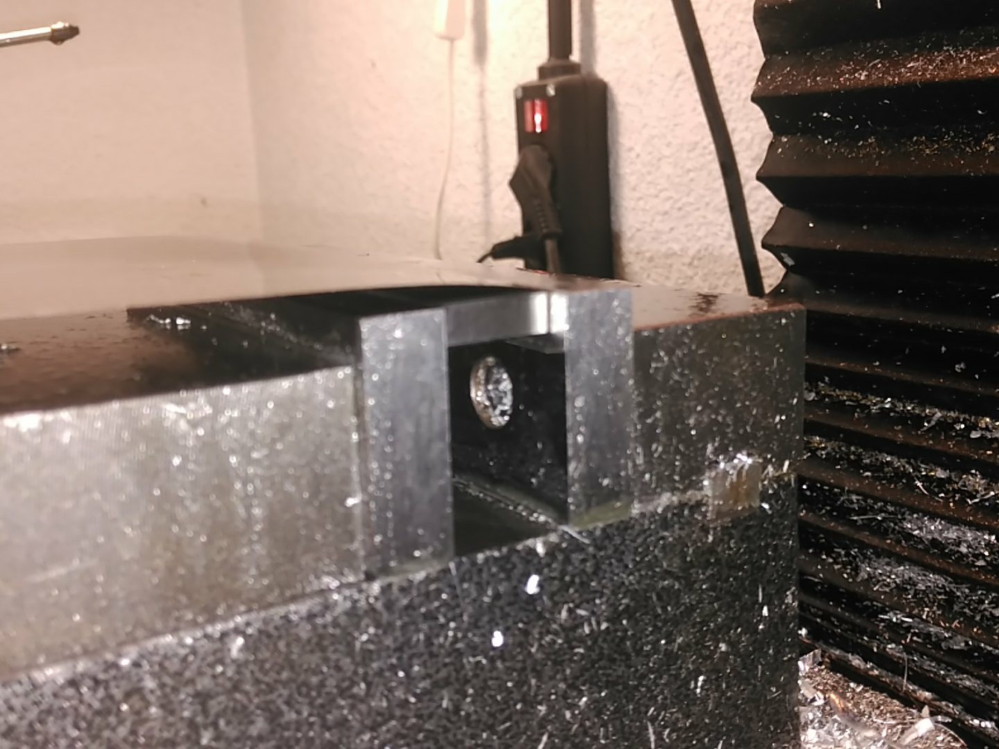
Everything looked great, so I embarked in the machning. Nothing in it was size critical, only the mounting holes, so I preferred to hand machine it, as my mill can remove much more material than my cheap CNC router can.
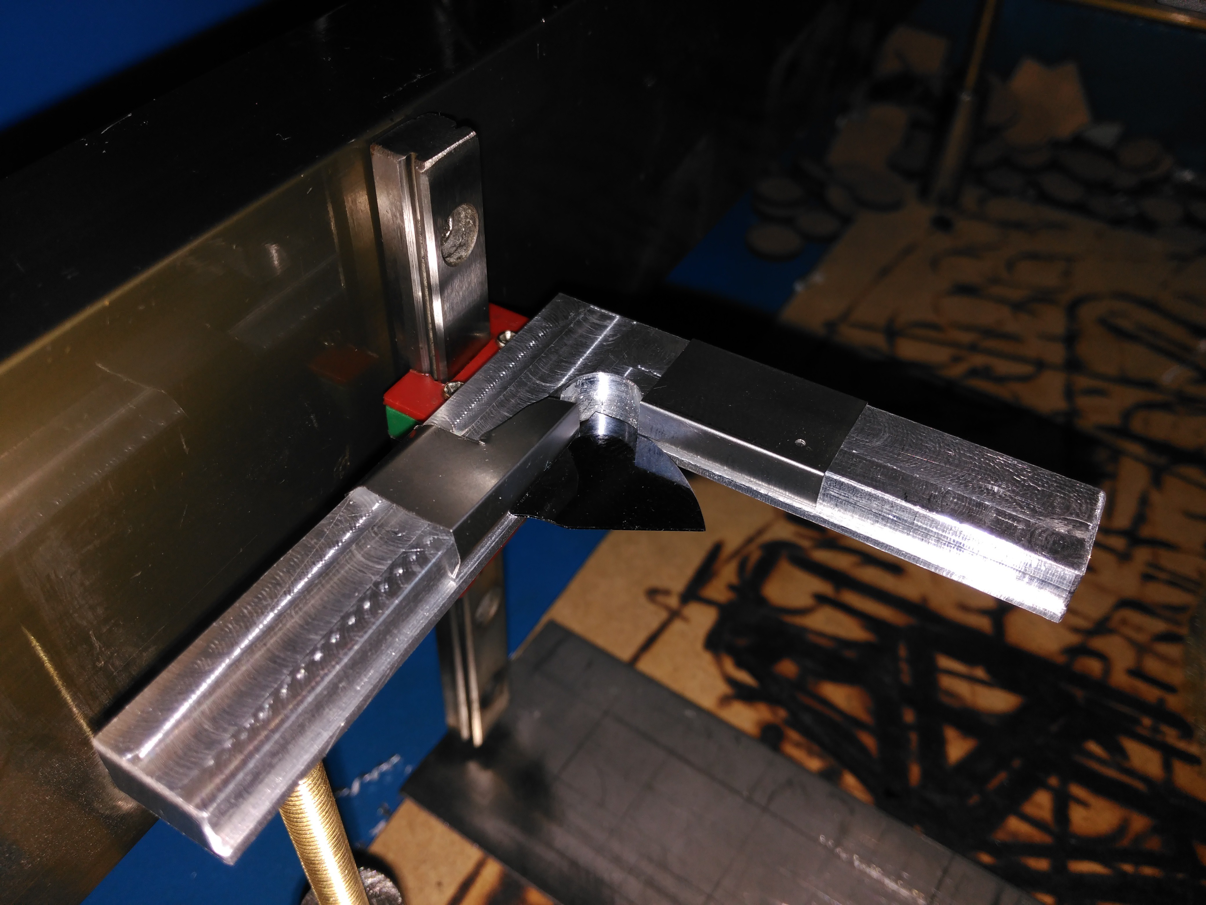
Holding is done through flat springs, sitting against the small 1mm ledges in the piece, and made pretty much like the cover in the hot plate:
(The ones in the image are just temporary, better ones will be made. To prevent chipping, the side in contact with the silicon is rolled, so it presents a smooth surface.)
Up until now, I had been using the oven at a lower temperature, as a makeshift hot plate/convection oven to dry thin fims.
However, as I begin to use the oven for it's intended purpose (growin SiO2 and difussion) it becomes very counterproductive to use it for other things. So, a hot plate to dry the thin films was devised.
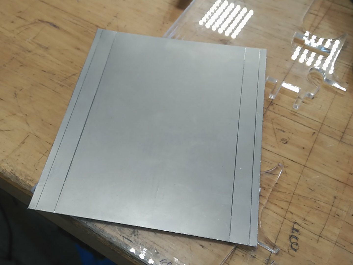
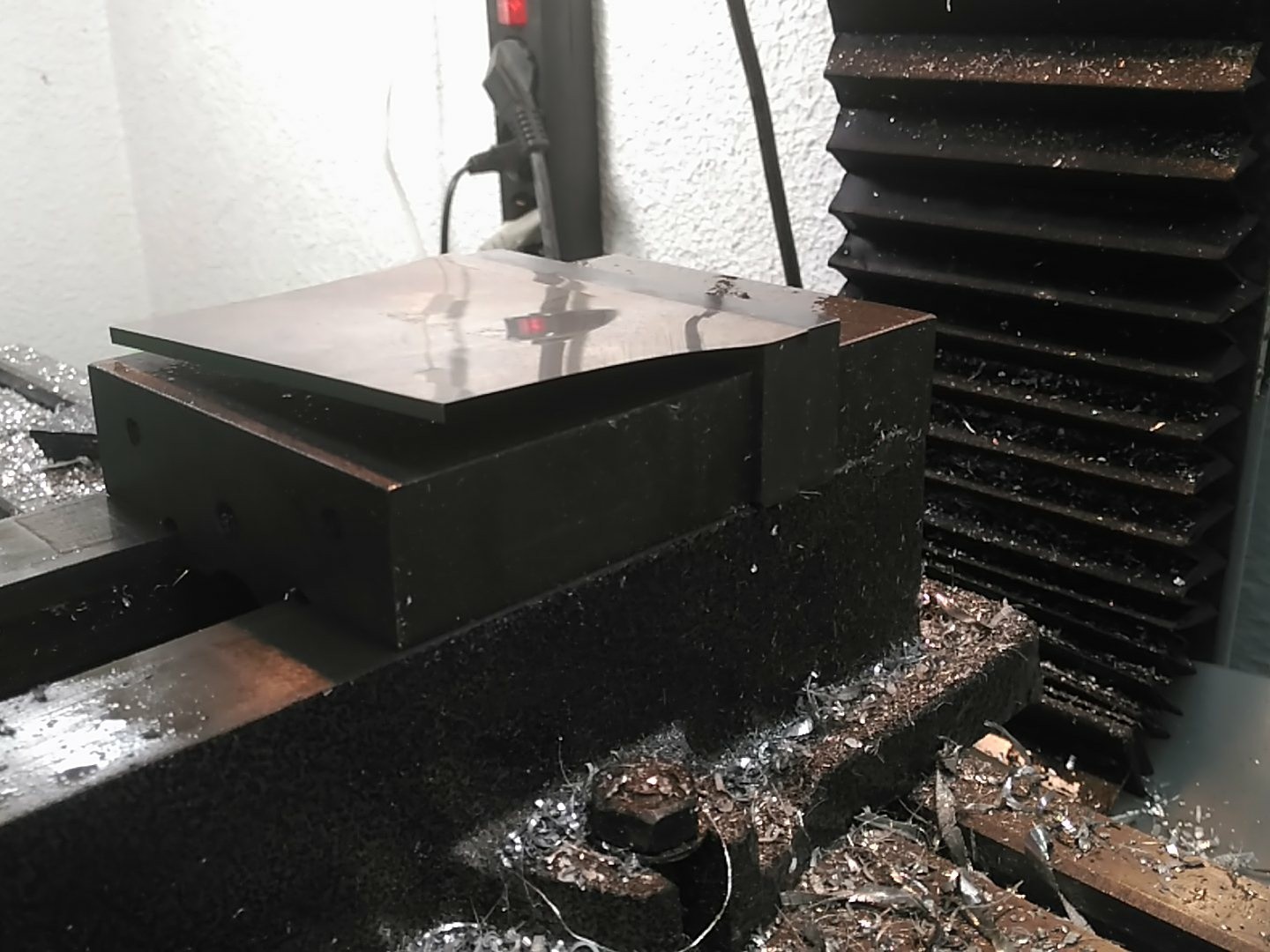
A suitable chunk of aluminium was procured from the workshop, wich offered enough space for multiple pieces and could hold in itself the heating cartridge I had around.
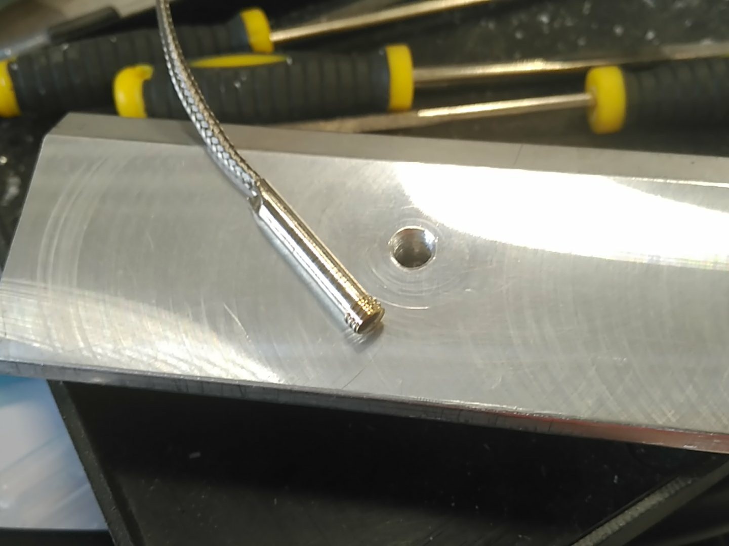
Drilled and milled:
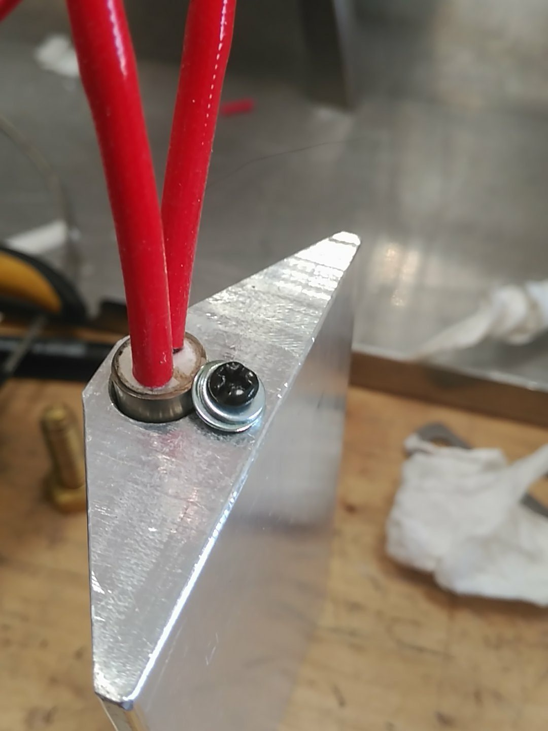
For the K probe, the retention screw had a weird thread I didn't had a matching tap for, so I ended threading the probe itself to M5 and screwing that into the aluminium block. Having it's head sitting just 3mm below the surface of the plate. Plenty of thermal compound was employed.
The heating cartridge was retained with a screw and plenty of thermal compound too.
Finally, I wanted to add some termic isolation to the bottom, so the assembly could be made compact. Ceramic matt tends to be fragile, so mechanical subjection is not recomendable. Instead, I scissor cut a piece of solder paste stencil and marked it with a cutter.
Clamping it into a vice, it was first hand bent and then shaped with a nylon mallet:
The inside corners where bent using a spacer:
With that and careful measurement, a super nice bracket for the ceramic matt was done:
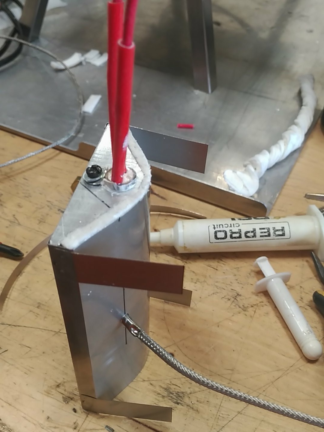
To further isolate the electronics from the plate, sheet metal legs where spot welded to the plate:
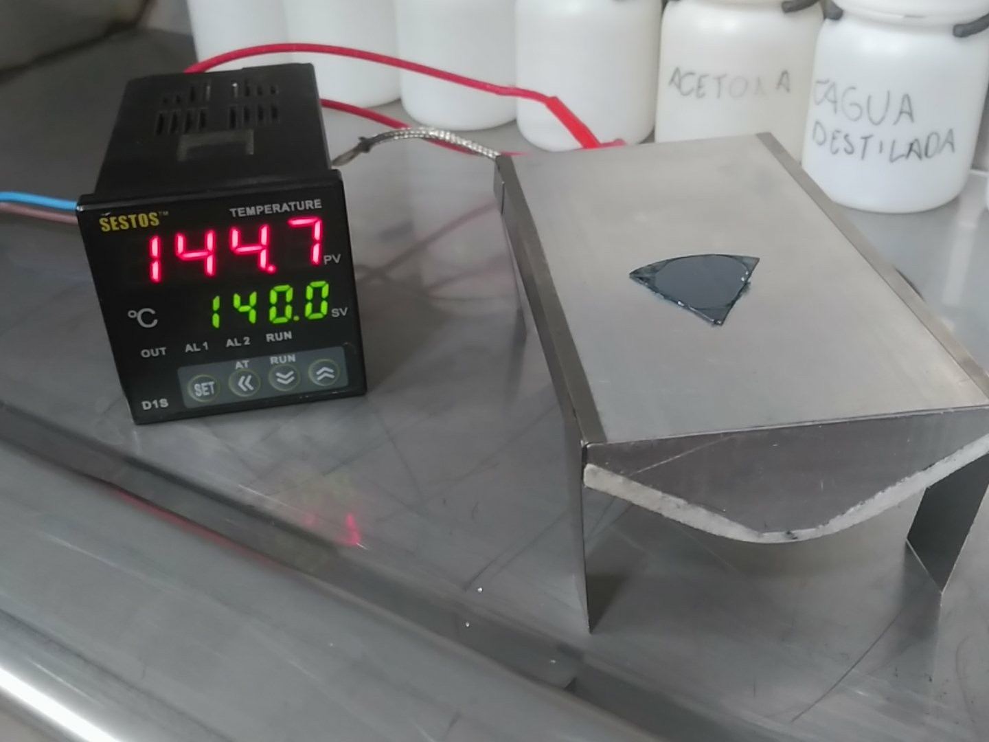
With that, but pending a different temperature controller with SSR capabilities, I connected it to an old controller I had around, and for now, I have a sketchy, but working hot plate!
Once I get the definitive controller, everything will be made much compact, with the plate on top of the controller + SSR, a nice case and some form of heat shield so you can't accidentally touch the hotplate sides.
The gear has been built. The oven, the sputtering rig, the spin coater and the fume hood.
The chemicals have been bought.
All thar remains is to test, test, test...and then more testing. I would hope to have some kind of semiconductor device (a diode?) by september first, time will tell, some say.
For now, I would recommend to look at my twitter account where I post my findings and experiments in real time (using it as a kind of log/documenting process).
With mostly everything ready to begin tests, bits of safety remained to be solved.
Since I will be working with dangerous chemicals, I didn't want to have the small bottles of them hanging around all over the place.
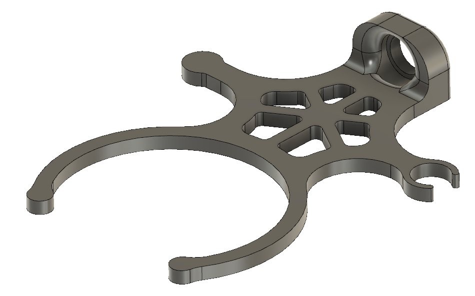
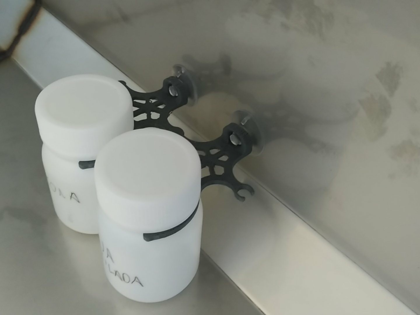
Thus, I came up with this:
This holds onto the bottle neck in the front and has a suction cup in the back, so it can be attached to the wall of the fume hood. It is also interconnectable with other pieces, so it can form a neatly arranged array:
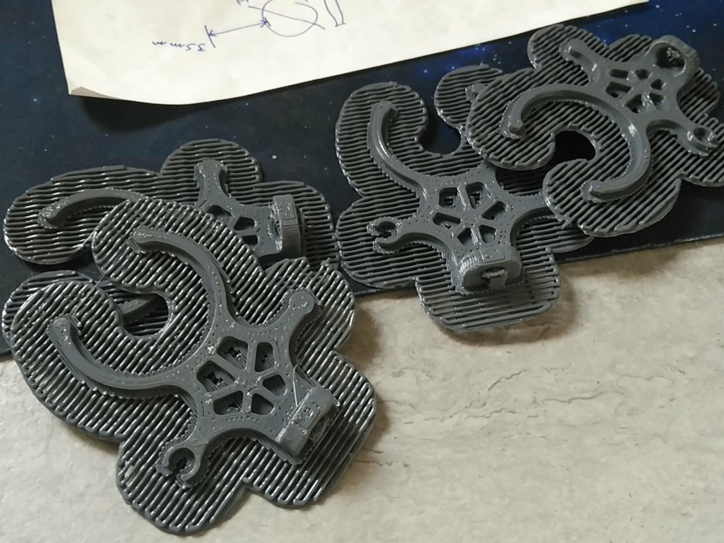
They are easily and fast 3D printed with a 0,6mm nozzle:
They should be improved by changing the 2D side connector (isc clamp) to a 3D version (ball clamp) so they can't slide out, altough that would be difficult with bottles in each holder.
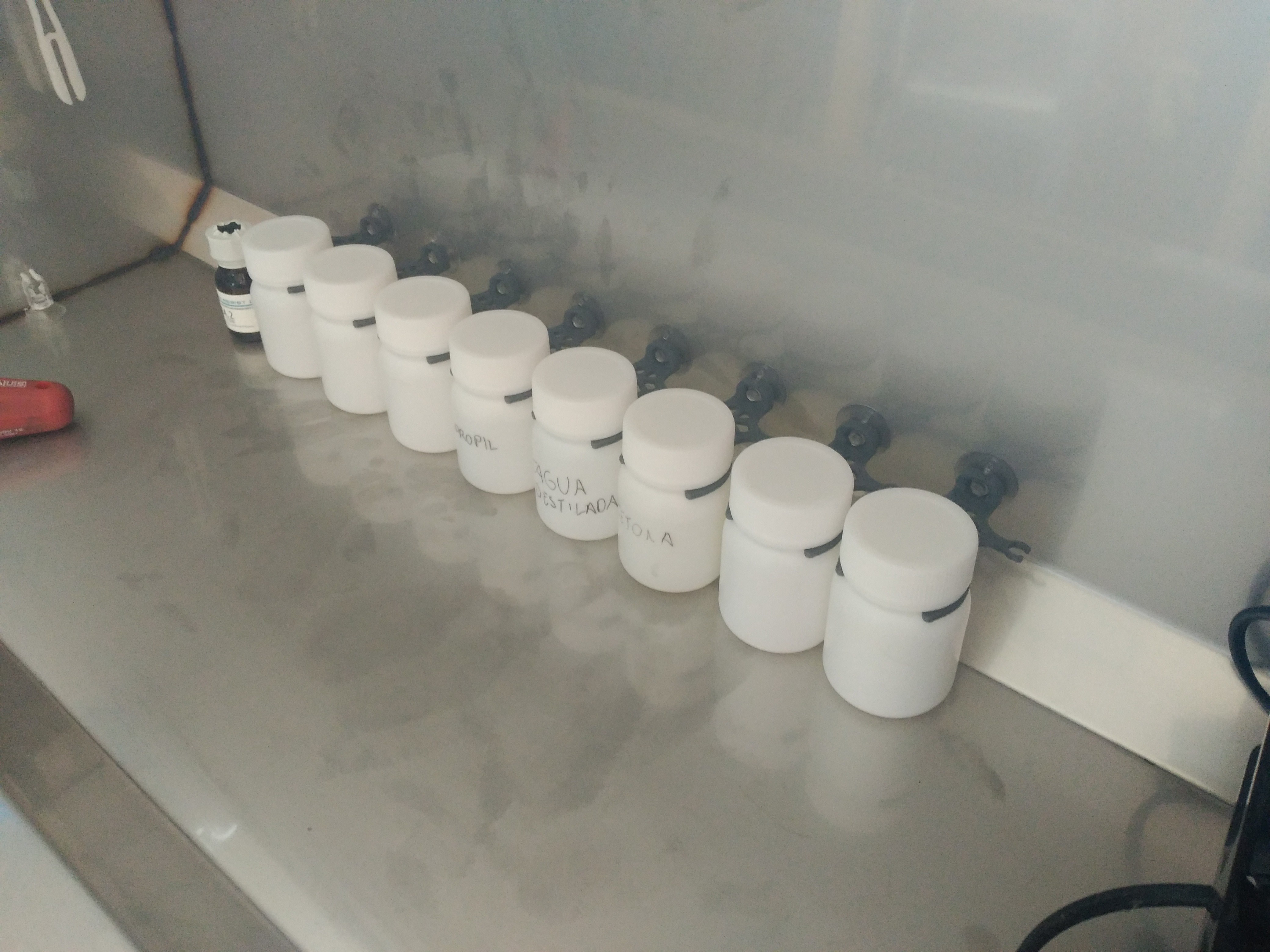
Huge array, in preparation of semiconductor tests:
 Nixie
Nixie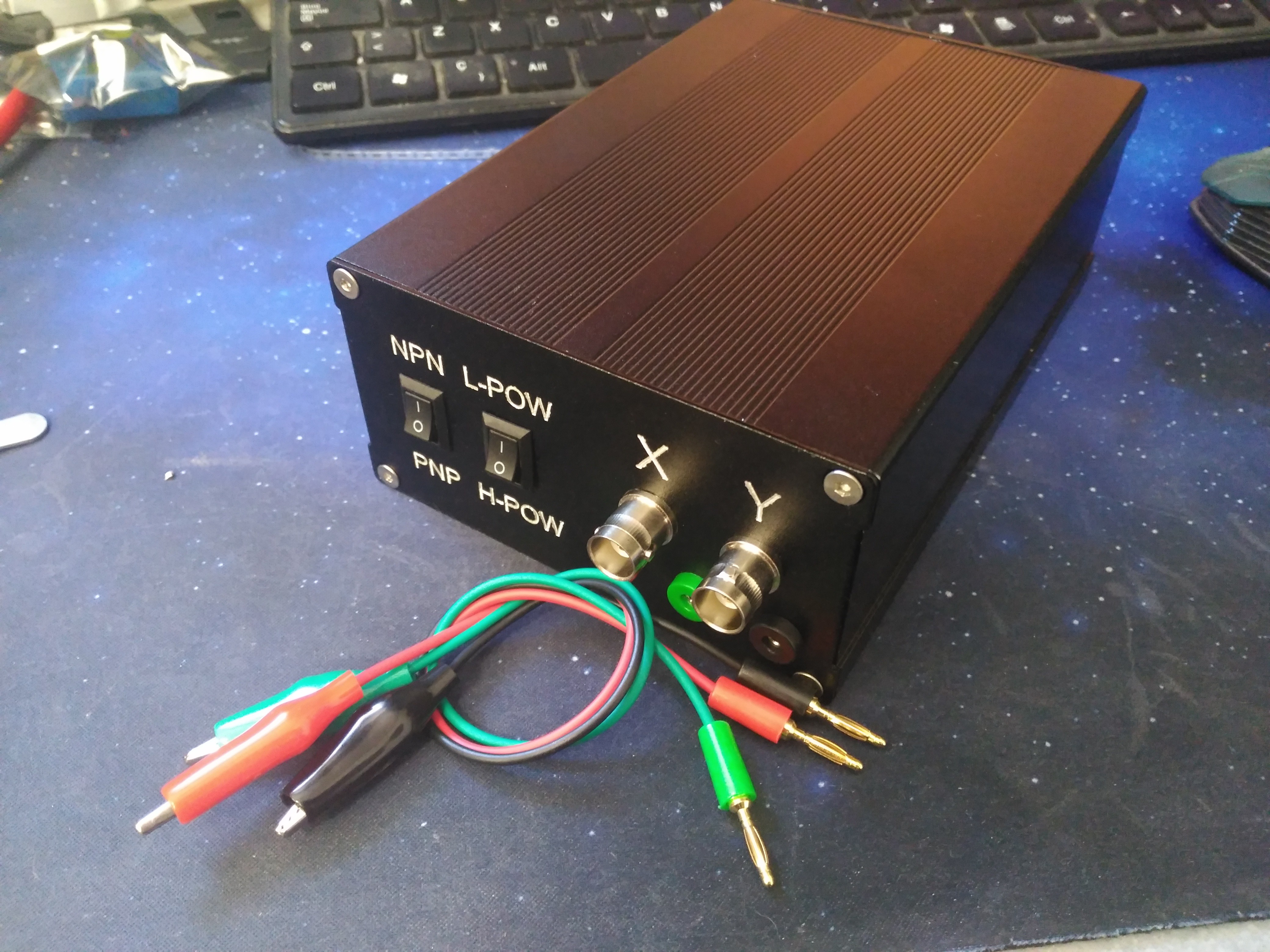

 (after diffusion, before etching)
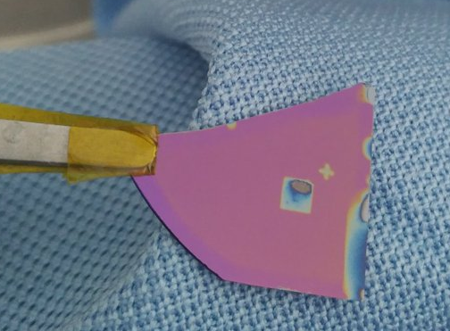 2mm test square and "+" fiducial. Should have left in HF longer, but curiosity got the best of me. ^^