Introduction
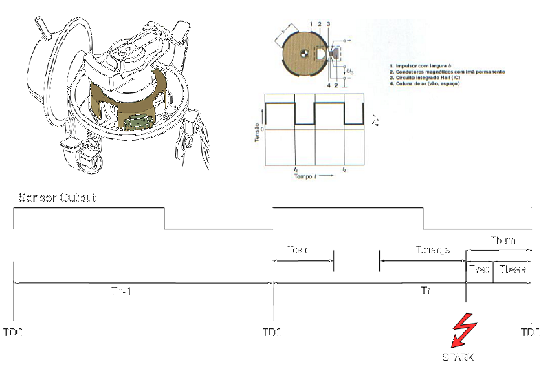
In a typical ignition system the high voltages necessary to burn the fuel are generated by a coil which is driven by a switching mechanism linked to the crankshaft. The switching is mechanically synchronized in order to provide the spark at the right moment, so the fuel has time to burn and push the piston with the power of the explosion.
Such process involves three important time related parameters: Coil charging time, Fuel burning time and Engine speed. The burning time also depends upon the load on the engine which is perceived by the vacuum in the admission chamber (manifold).
One of the problems of the ignition system is that both the charging time and the fuel burning speed are nearly constant allover the engine speed rate, which required some compromise solutions even in the systems with electronic ignition:
- The coil charging time was set about 50% of the time (Dwell time) and the current is limited by the coil internal resistance (a series resistor is also used in some systems). The current limitation implies in a spark with low energy, specially during startup where the battery voltage can drop down to 8 Volts.
- The burning time is changed according to the engine speed by the use of mass and spring mechanism (centrifugal advance) and with a vaccum capsule (vaccum advance). Both mechanisms provide an angular displacement that is tuned to match with the timing required by the engine, but the dispersion of parameters specially on the springs used in both mechanisms is high and you can't find spare/alternative springs to buy, only assembled parts which in turn are physically alike but have different part numbers and no information available.
The present project tries to address both of problems by providing precise timing of both coil charging time and spark release with the minimum addition of parts and adds some safety features.
Design
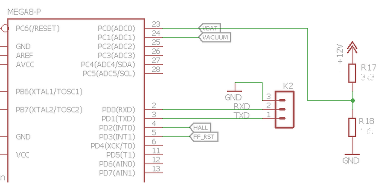
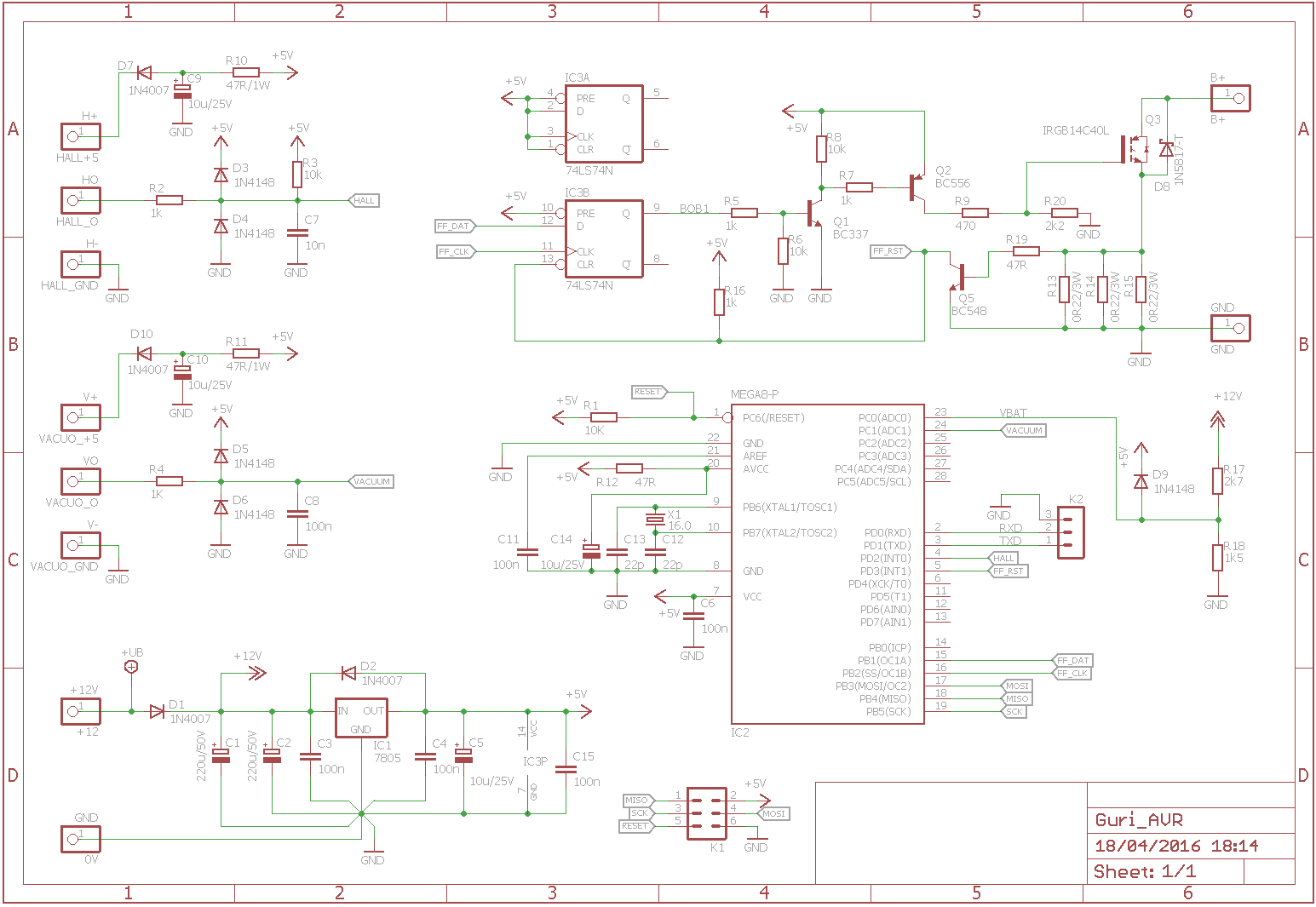
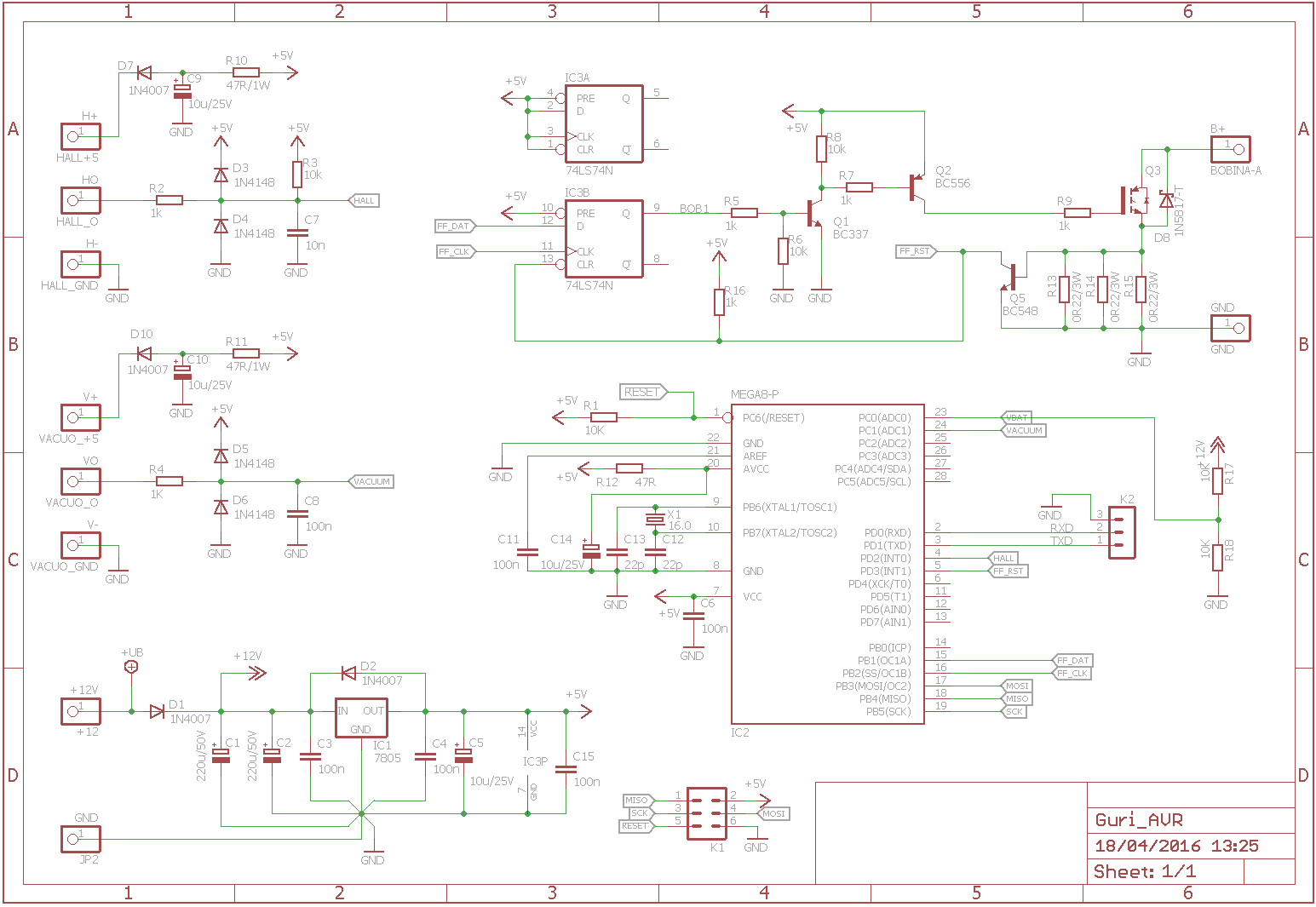
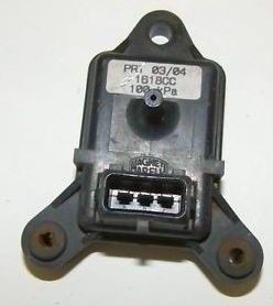
The circuit was designed to stand between the original sensor and the coil. It consists of a Micro controller, a MAP sensor and and a Power Transistor.

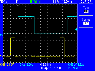
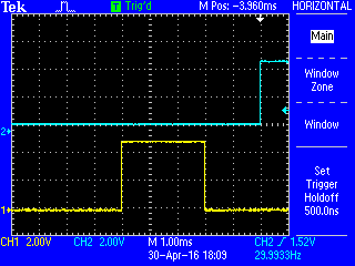
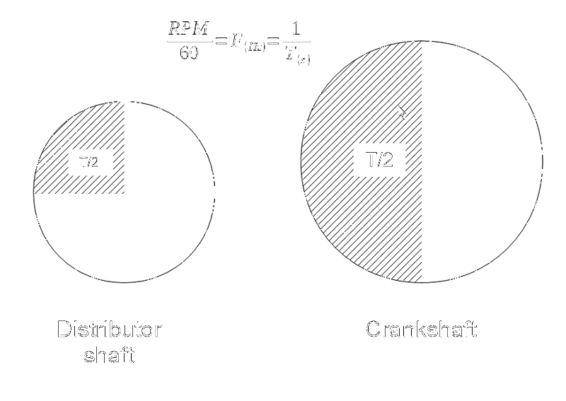
At the TDC the microcontroller measures the time taken in the previous cycle (90° of the distributor shaft). Then the software assumes that the timing of the next cycle will be close enough from the previous cycle, i.e. it assumes that the timing between two cycles is nearly constant (the rate of change can be considered in the calculation using a filter or a PID calculation, tough). Then it adds the base timing with the vaccum timing to calculate the moment of the spark. From the Spark time it subtracts the coil charging time and calculates the moment of the starting of the charge. Both times (Start of Charge and Spark) are programmed in two timers which in turn will generate an interrupt that will turn the coil on and another that will turn the coil off, thus generating the spark that will generate and explosion which will peak a bit after the TDC.
Software Architecture
The basic software architecture consists of a main loop and several interrupts.
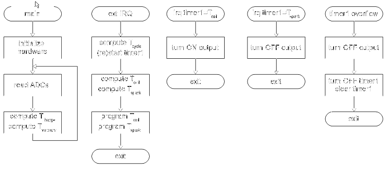
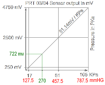
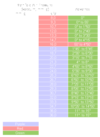
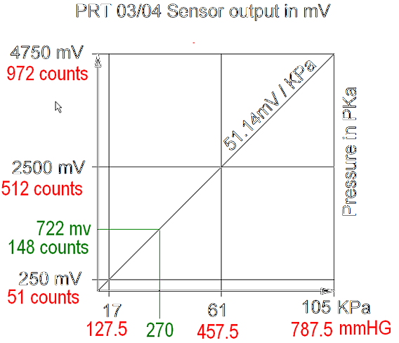
The main loop is where the ADCs are read. One of the ADC channels reads the car battery voltage and use the value to calculate the coil charging time. Another channel is used to read the vacuum signal coming from the MAP sensor and provides an additional time for burning the mixture.
The external interrupt is used to measure the time it take for the engine to turn 180° which is sensed every 90° on the distributor shaft (which runs at half speed of the engine). From this time it is subtracted the base time (around 2ms) added to the contribution from the vacuum sensor and resulting in the time Tspark which is the moment where the spark must be generated. Then, from Tspark is subtracted the coil charging time and the result...
Read more » danjovic







this is awesome work. a system like this would be perfect on my 1965 VW Notchback!