uri.shani
-
Long overdue update - code snippets + hardware
02/05/2020 at 20:17 • 0 commentsI've mostly abandoned this project, but nevertheless I decided to include here some things that worked, some that didn't, and a link to a sort-of-working code.
First - The MIDI + LCD controller didn't work. I cannot recall the exact error, but the reason, if I recall correctly, was the difference between the USB bridge and MIDI UART's pull-up vs. pull-down. If there'll ever be another iteration, I suppose working with a uC that has native USB + a separate USART make that much much simpler.
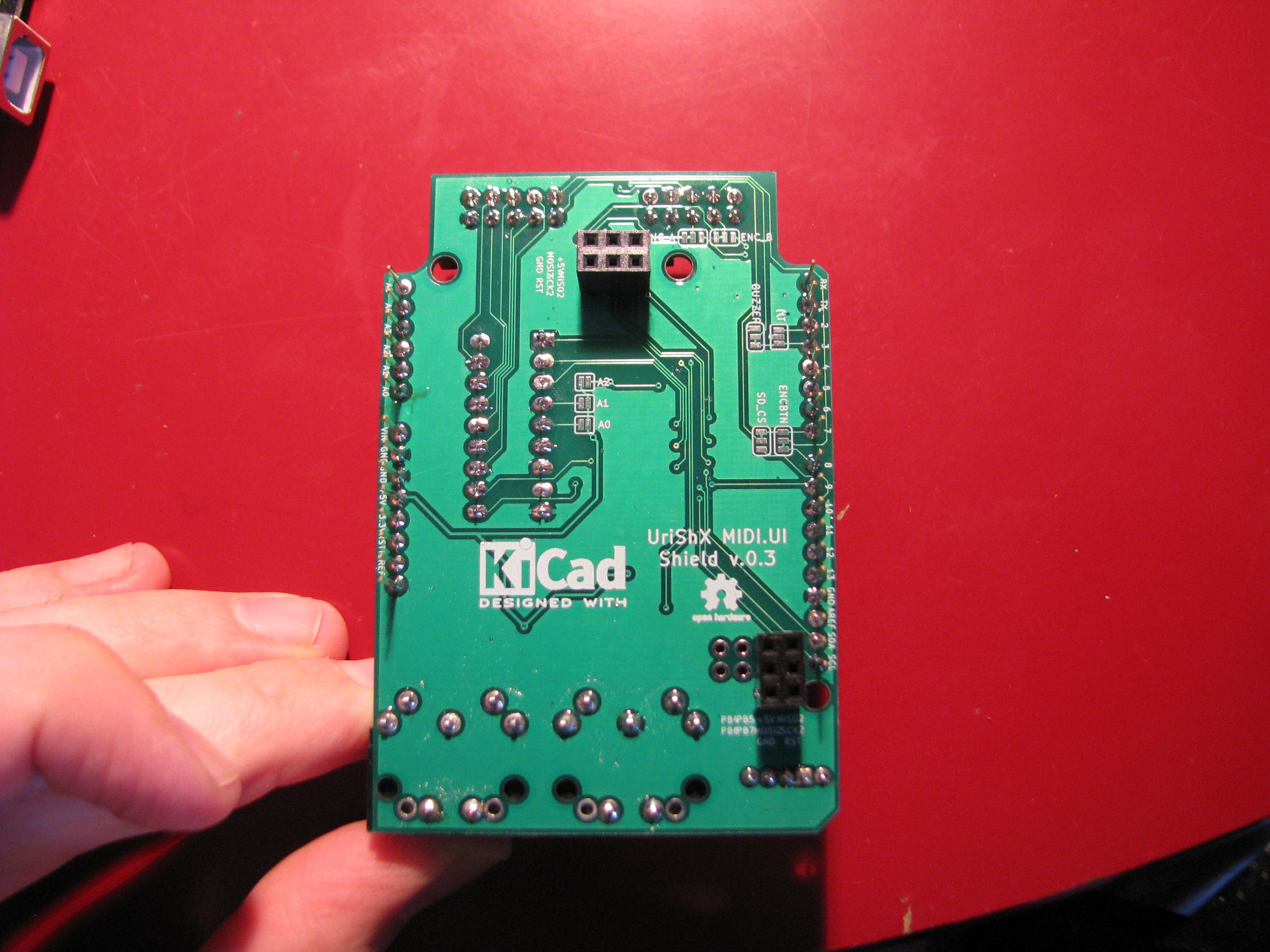
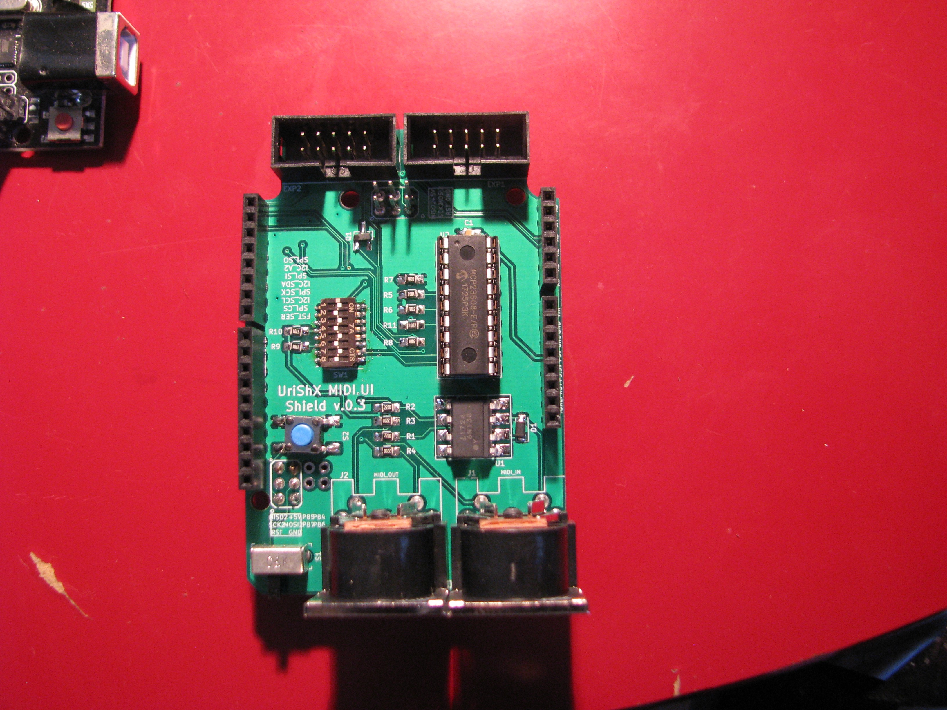
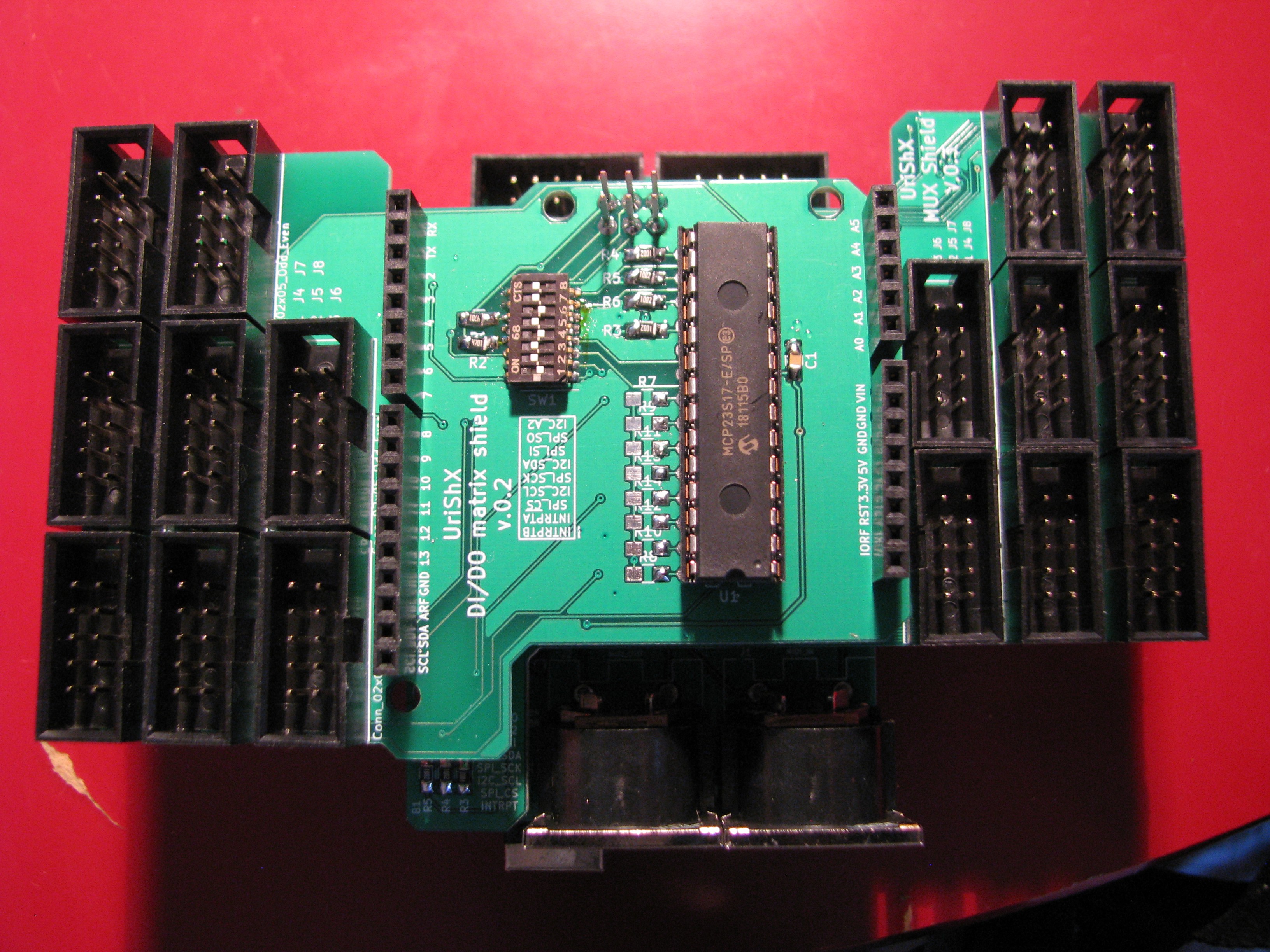
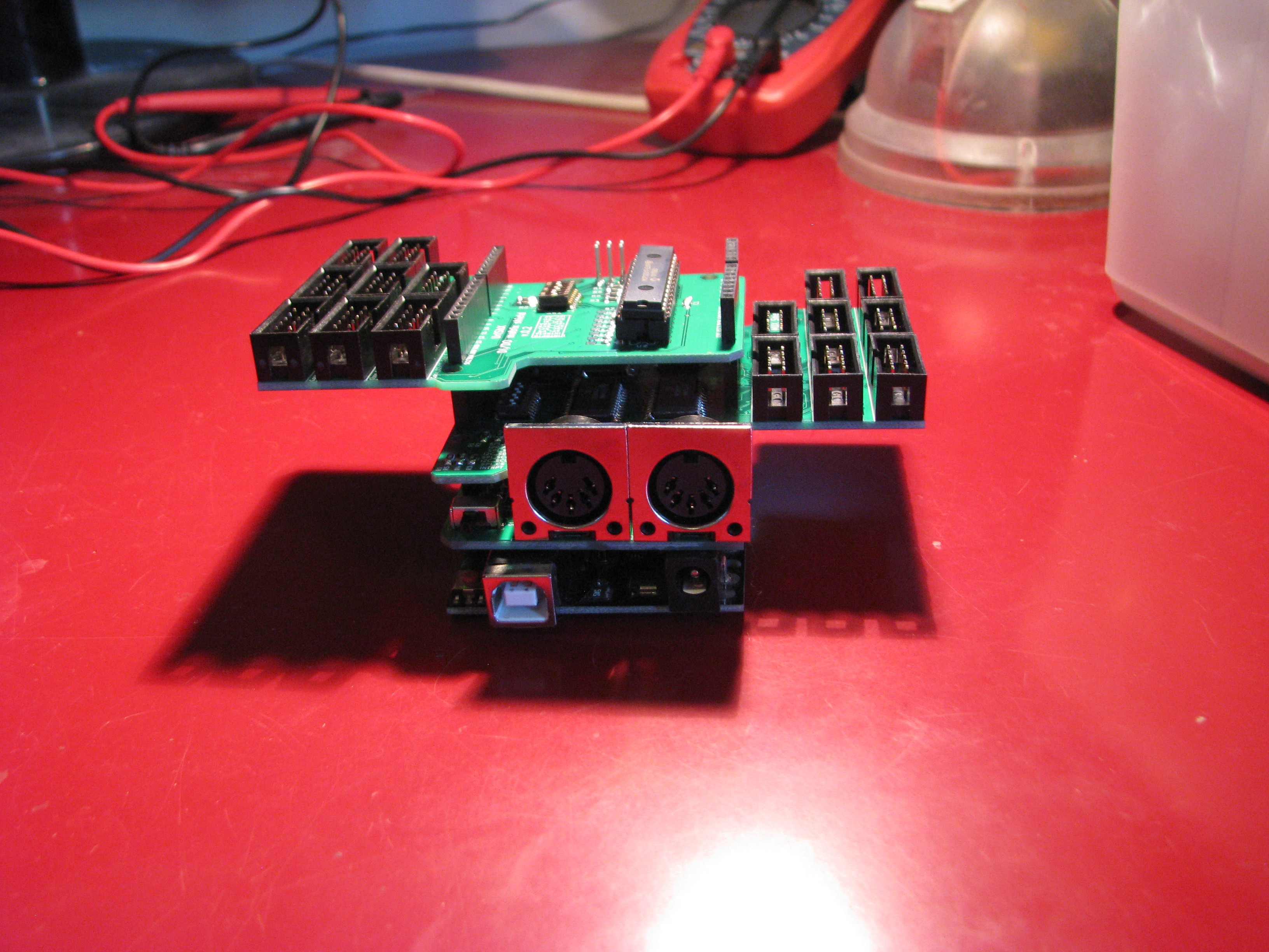
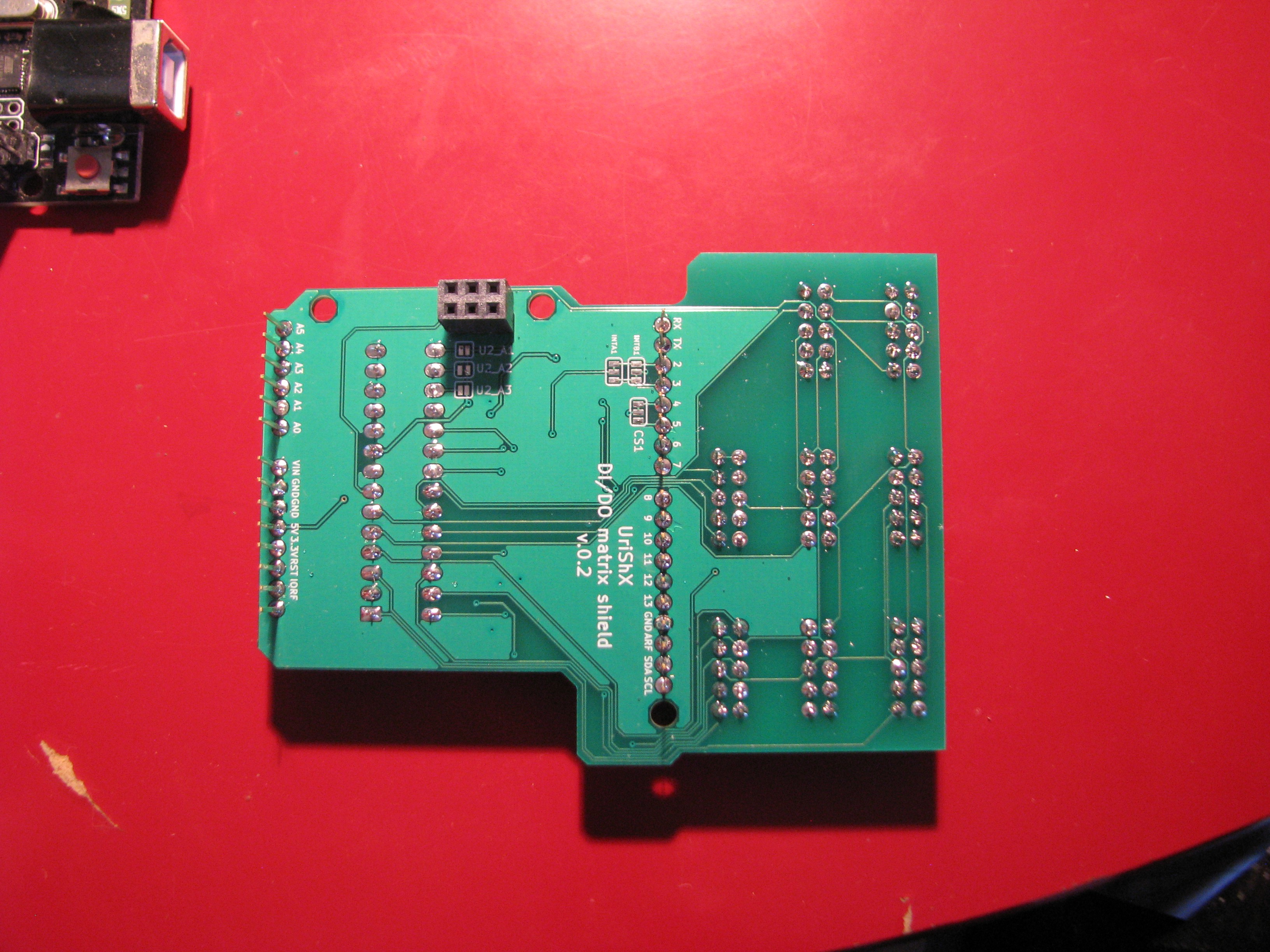
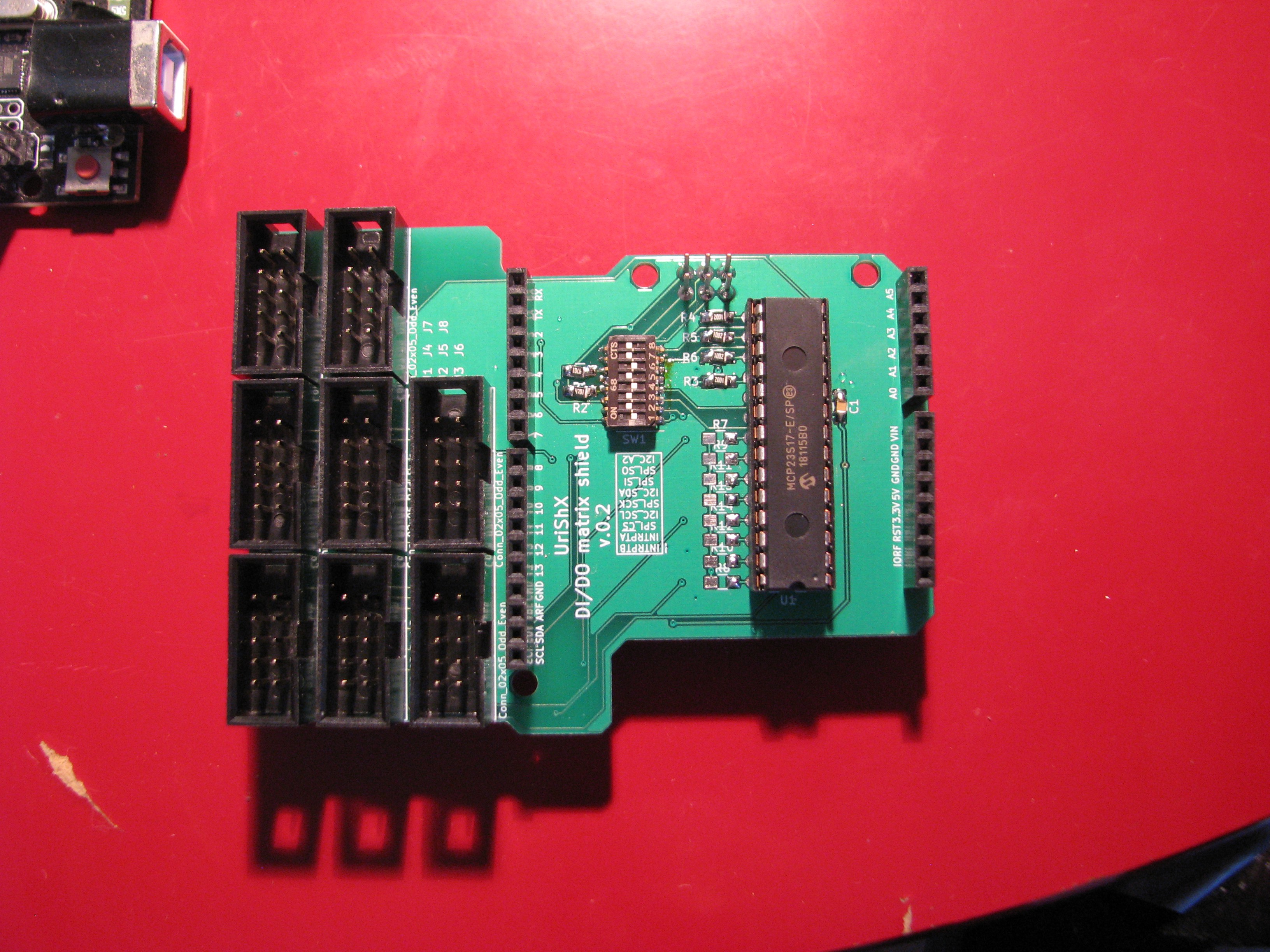
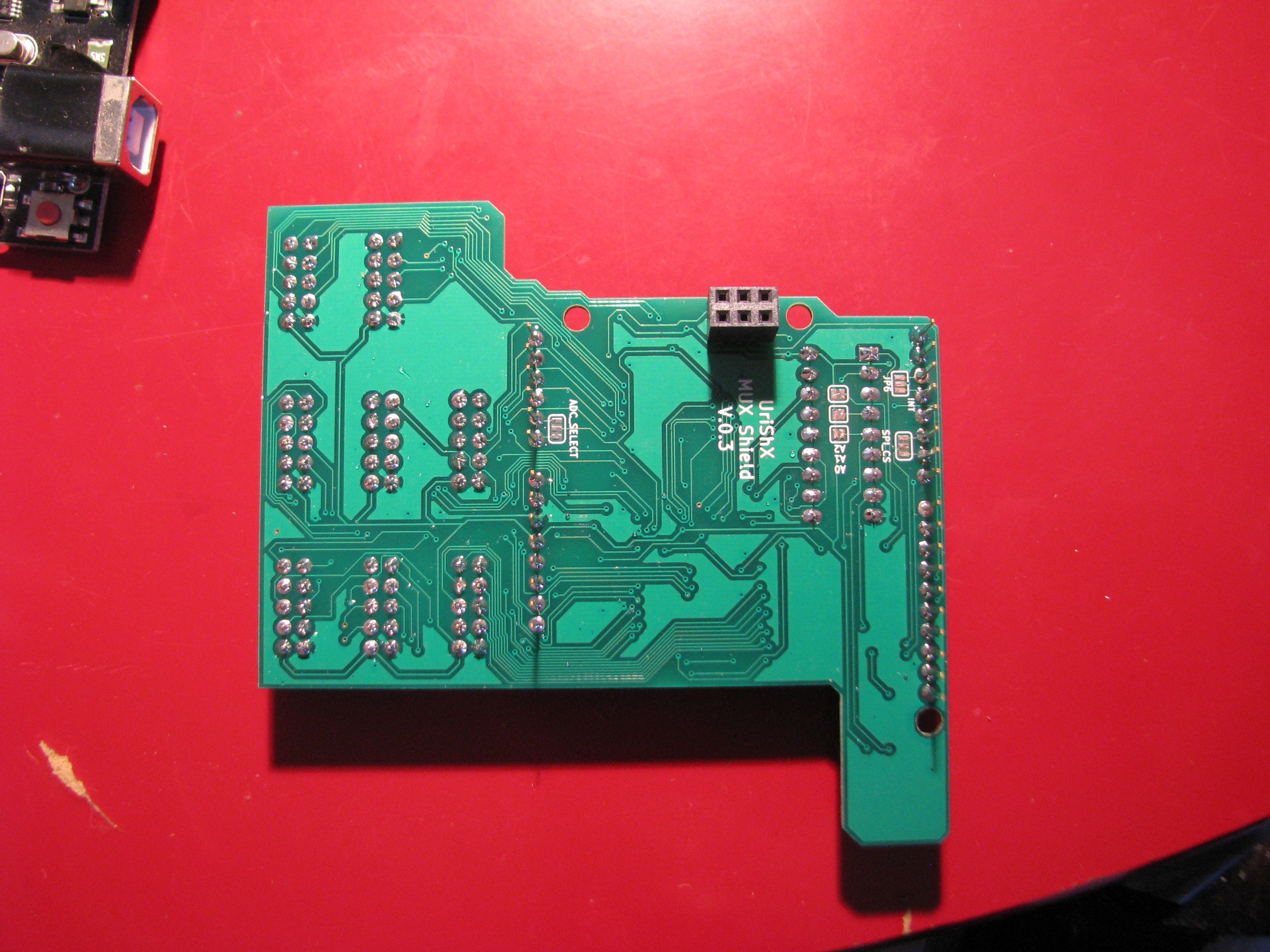
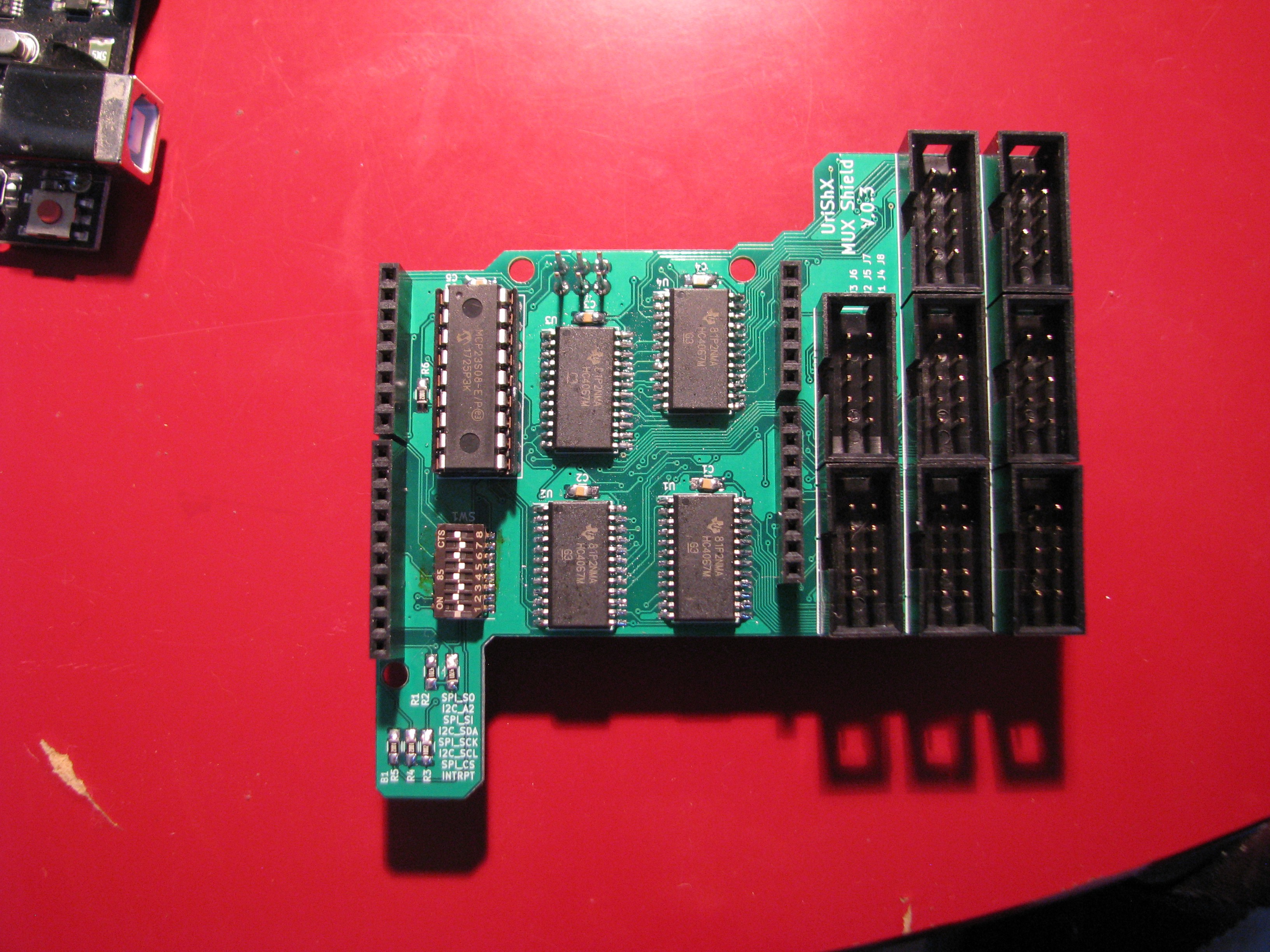
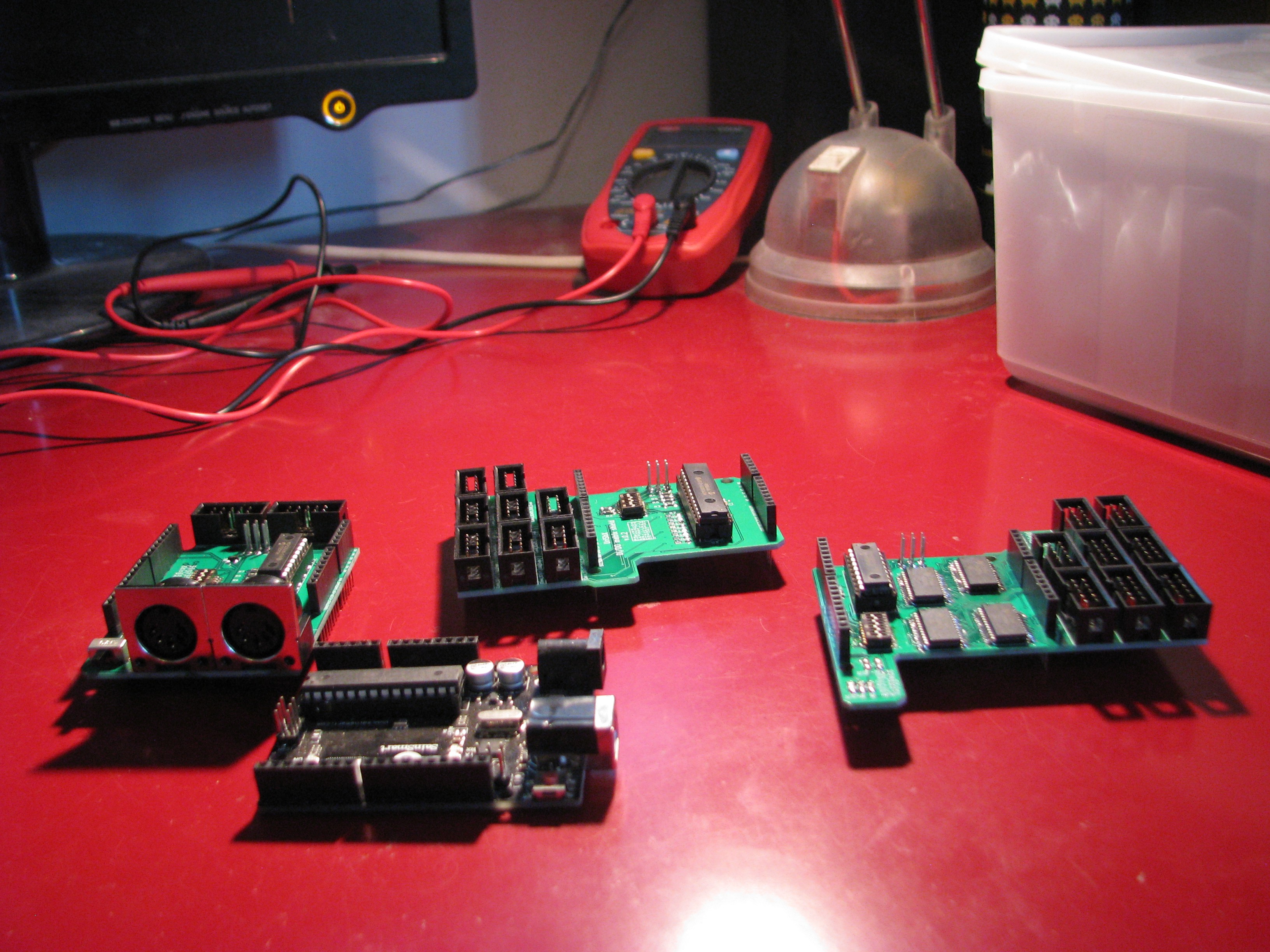
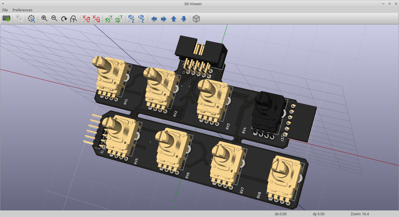
Second - I updated the hardware repository, to include my best efforts to fix issues with the first iteration. I actually think the mux & 64 button DI shields work quite well. I tested them with code that's hosted at these gists (1, 2). The code is dirty and uncommented,
but hey - that's better than no code, right?
Here are some pictures of the the boards:
![]()
![]()
![]()
![]()
![]()
![]()
![]()
![]()
![]()
![]()
-
Day before challenge starts
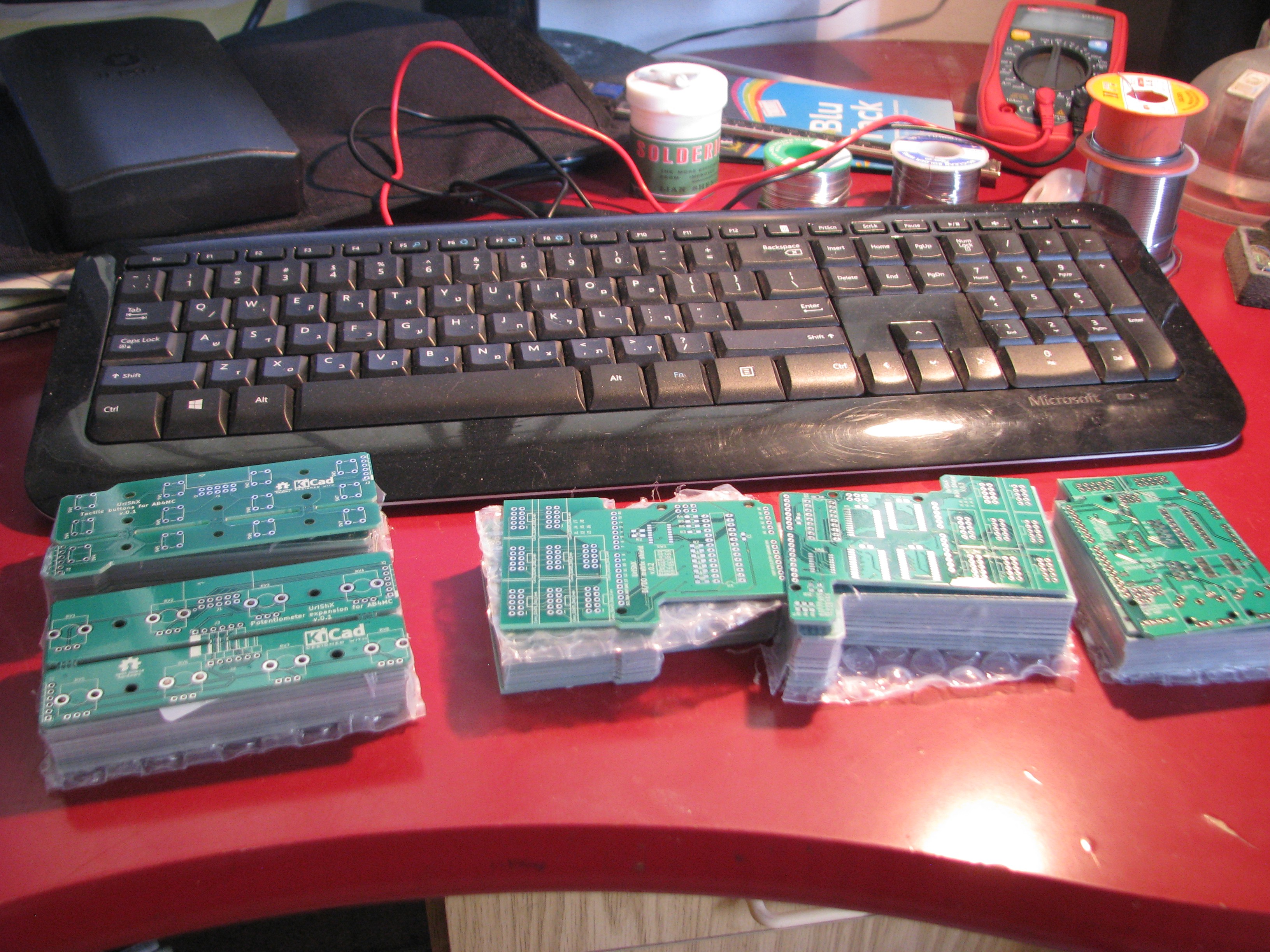
08/27/2018 at 07:23 • 0 commentsI've been hard at work in the last month or so, redesigning all the boards to overcome the issues I found in the first revision. Last night I got a message they were finally drop shipped, and hurried to get them. Just in time! Hopefully by the end of today I'll have some assembled, working boards.
![]()
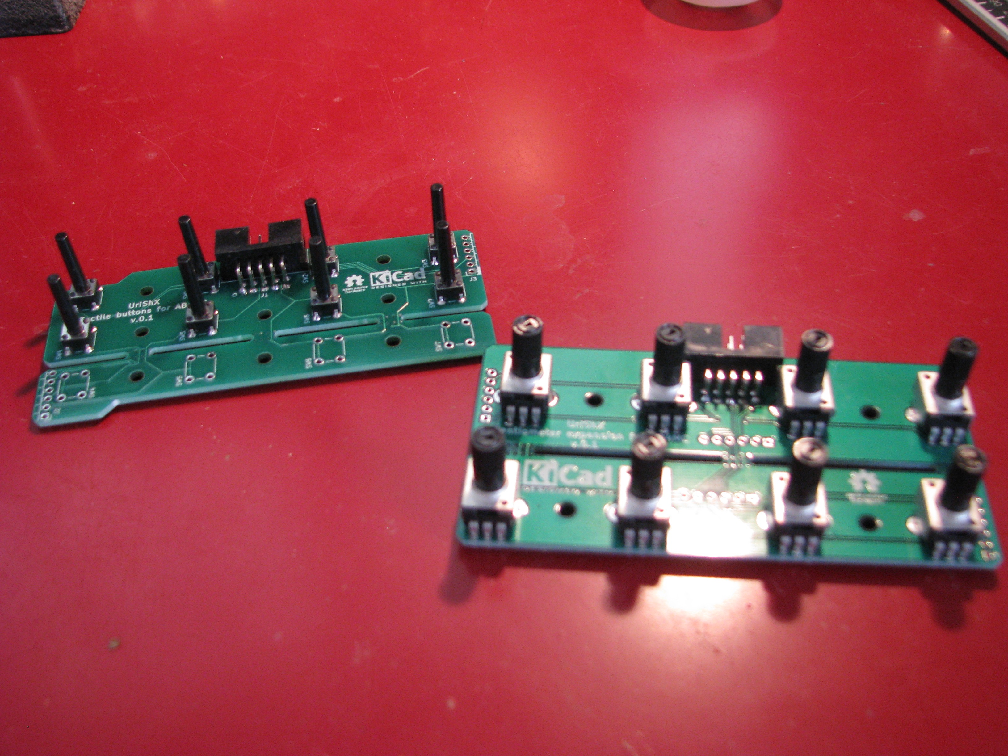
I've also added two new boards - a modular potentiometer expansion board, and a modular pushbutton expansion board (on the left). I got the parts for these from some sellers I found on AliExpress, since I needed there to be enough parts for making an actual interface and the prices were a lot cheaper than getting pots and buttons from Digikey. Sadly, that means I'll be waiting quite a long time for the cheap shipping option. I sure do hope the parts will get here in time. If not, I'll have to come up with some other plan for a working prototype.
-
Redesign, UX considerations, and survey
07/07/2018 at 10:41 • 0 commentsI published a short survey this week on facebook and twitter, aimed at helping me understand more what are the main reasons people don't just go and build their own MIDI controller. If you follow this project, it will be great if you could share this, so I'll get some more replies.
Now more to the point - while I was testing my first designs, I wasn't thinking of a full test procedure, but rather of getting everything to respond. Moving forward to writing comprehensive blocks, I was building the full functionality into the Arduino model sketch, and I came to realize how flawed my design was. So - it's redesign time!
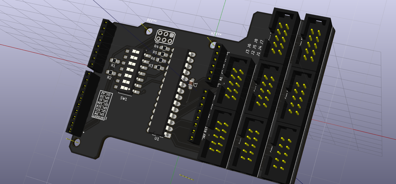
First, I redesigned the DI/DO matrix shield. I updated it to use a single MCP23x17 , and based on Microchip's app note, I've also eliminated most of the small components. Should have done that before I went ahead with the first design, as it wasn't based on an I/O expander, but on shift registers. The app note states that pullup resistors on the inputs help define the time between allowed button presses, but I decided not to include those in this revision. If the current revision will prove to be too "jumpy", I've left enough space on the board to allow for the addition in the next iteration.

The PCB is not yet fully decided upon, but here's a snapshot:
![]()
I still need to think whether to keep using DIP packages, so the user can use either I2C or SPI, or go the more economical route and use SOIC packaged chip, along with preconfigured solder jumpers. Since I aim in some way to make these boards somewhat of an introduction, I think that perhaps the DIP chips may show the intended (novice) user it's possible to make changes. As I learned from my first iteration, all cable connectors were moved to one side of the board, and were changed to 10-point IDC in order to standardize the system. The connectors on the analog MUX shield will be all moved to the opposite side, which will free some space for using both shields at once.
Next, I started designing the peripherals. I started out with an 8 rotary pots plug-in for my analog MUX shield. The pots are on 25 mm between centers, and the two lines can be broken at the tabs and the pots rearranged on a single line. I'm still not happy with the placement of the IDC connector, and will probably need some cardboard cutouts to play with until I'm satisfied.
![]()
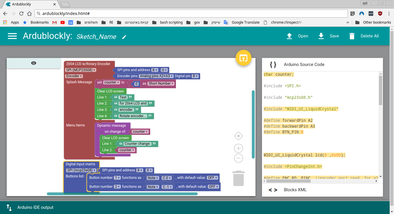
I've also showed the blockly environment to some friends, and got their opinion on looks and feel. I've changed some things in the overall design, for usability. First, I changed the color scheme to imitate what most musicians are used to. I've also made programming the Arduino with the code a bit more accessible (in my mind, at least), by giving the user only the possibility to download the code and open a new window with the Arduino online IDE. I believe that serves both the purpose of shortening my development time, but also to show future users that the Arduino community is quite large, and it is quite easy to explore further if they wish.
-
Long overdue update on shields and block design
06/14/2018 at 07:44 • 0 commentsI just realized I haven't updated this project in a _very_ long time!
I've been actually busy troubleshooting the shields, and making my way through designing the blocks for programming.
The analog multiplexing shield run OK, and allows for reading up to 64 analog inputs through Arduino A0 (can be changed to A1).
The digital matrix took quite a long time debugging. I mounted two individual MCP23X08 on the shield in a matrix configuration, and used the inbuilt interrupt pin to signal the Arduino to check the state of the pins. Most of the debugging was due to the elusive "digitalPinToInterrupt(pin)", as in:
attachInterrupt(digitalPinToInterrupt(pin), ISR, mode);
For some reason this function call is needed when using an Uno (didn't use to be), and it took quite a long time for me to find that out. There is very little detail on that function call, and it seems older code that does not include it doesn't work anymore.
On the topic of the digital matrix shield and the use of two MCP23X08 - I think I'll change that up for a single MCP23X17, and also get rid of all the unnecessary diodes and resistors. I believe that the I/O function of the chip itself should be good enough for what I'll be using it, especially with the built in pullup resistors.
I settled on Ardublockly as my block programming UI. It's both better documented and has got a better support network (through Google's Blockly). It also looks nice, and it's looks can be further tuned through CSS. In the following image are the blocks designed for this project up till now. Far from completion, It's a start, and I'll be designing the blocks for the next few weeks, to get the quick drag-n-drop MIDI capabilities I want.
![]()
-
MIDI.UI board update
04/29/2018 at 16:42 • 2 commentsJust a quick update: In the last week I've been checking and verifying the LCD / MIDI shield. I found some things I forgot to do, like marking the MIDI / serial switch, but more importantly, I found out two major design issues.
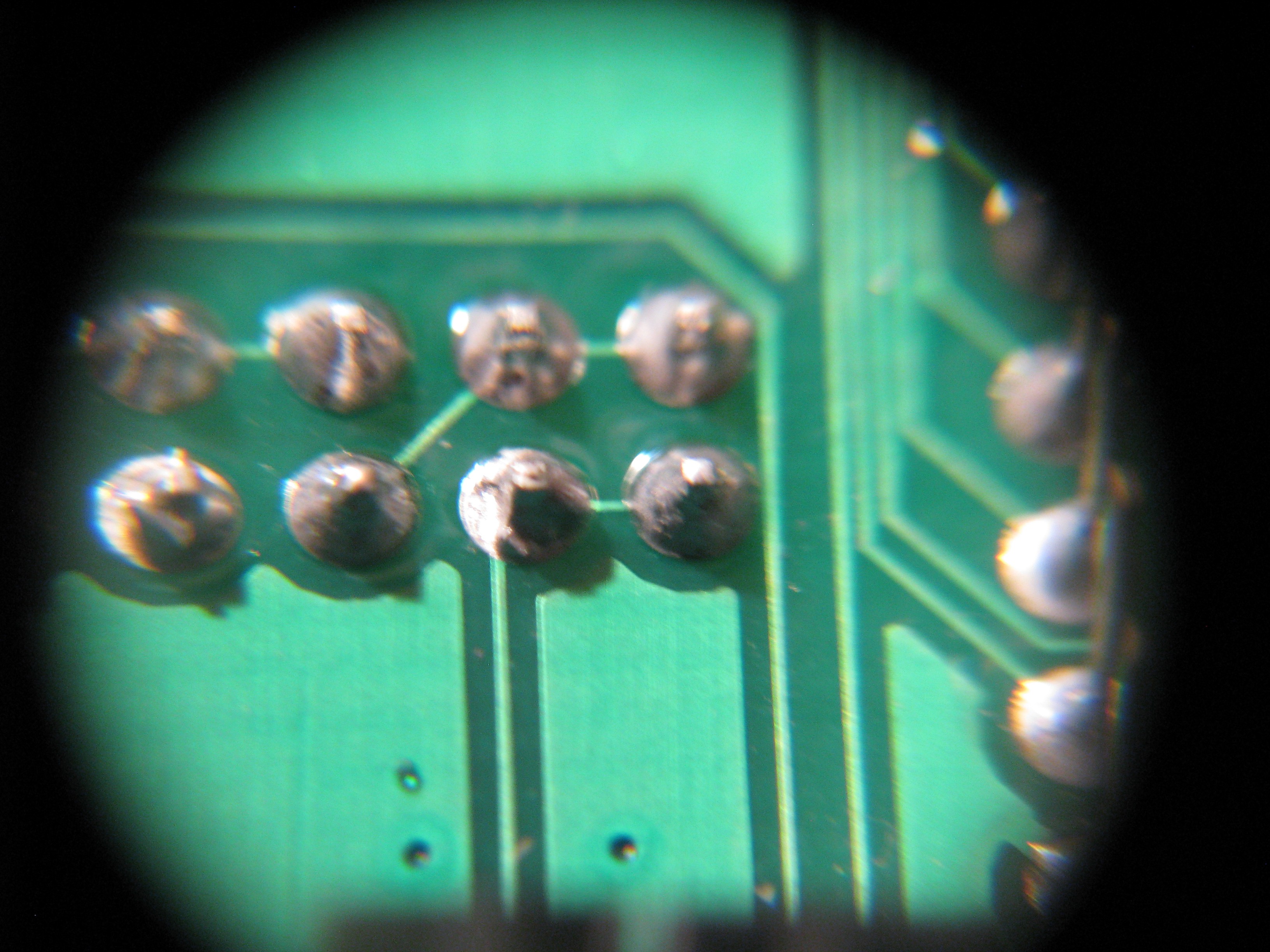
In my schematic capture I replaced and misplaced the RX / TX jumper pins. Since I'm using mocoLUFA as a basis, I wanted to be able to use either the ATmega328p OR the Atmega16U2 for serial MIDI. That way, I can transmit serial MIDI between the two ICs at a much higher rate, to free up important calculation time from the 328, and use the 16u2 for both USB MIDI and add software serial to it. The USB MIDI function uses a circular buffer, so I think it might be possible. Anyway, since I misplaced the names of the pins, when I got to PCB design I jumpered the pins from the hardware serial on the 328 to the intended soft serial on the 16u2. Somehow, when I checked the GERBERS I missed that. when I populated the board and started checking my PC couldn't find the board, and when I checked I found this:
![]()
Jumpered TX pins, lower center I cut this trace, and it seems to solve this problem.
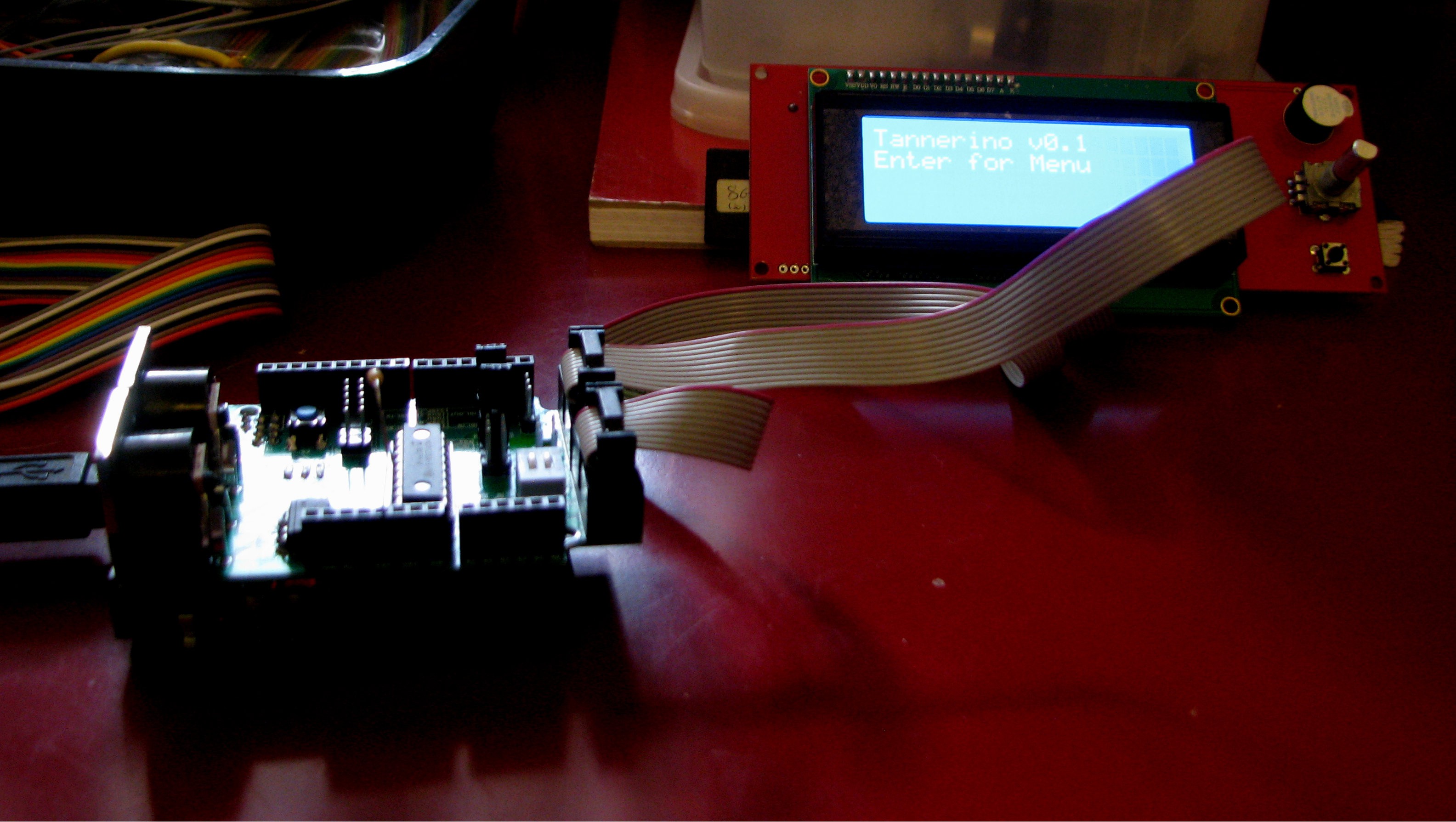
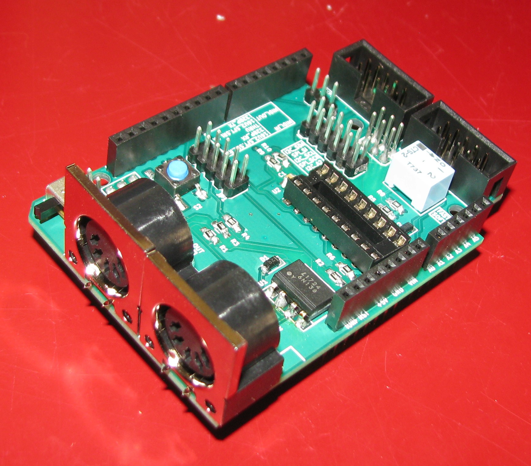
The other design mishap I found took me a longer time to find. It took me about a week (!) to find out I completely forgot to tie the reset pin high, and it seems I forgot to do that in ALL my designs. I was really banging my head to the wall trying to figure out why the design as it was did not work, as it's more-or-less a copy of the Adafruit LCD Backpack. Anyway, for the time being I'll just solder a non-smt 10k resistor hanging in mid airso I can go on. This does seem to work, as can be seen in the next picture.
![]()
There's still Serial MIDI to check, but I've checked all other peripherals of the RRD Smart Controller, and I've been working on implementing a SPI counterpart to the I2C seen in the picture (MCP23S08 instead of MCP23008).
I also found that the placement of the ribbon cable connectors is far from ideal when one wishes to combine the shields. But I'll get to that in a later update.
-
Bringing up my first board
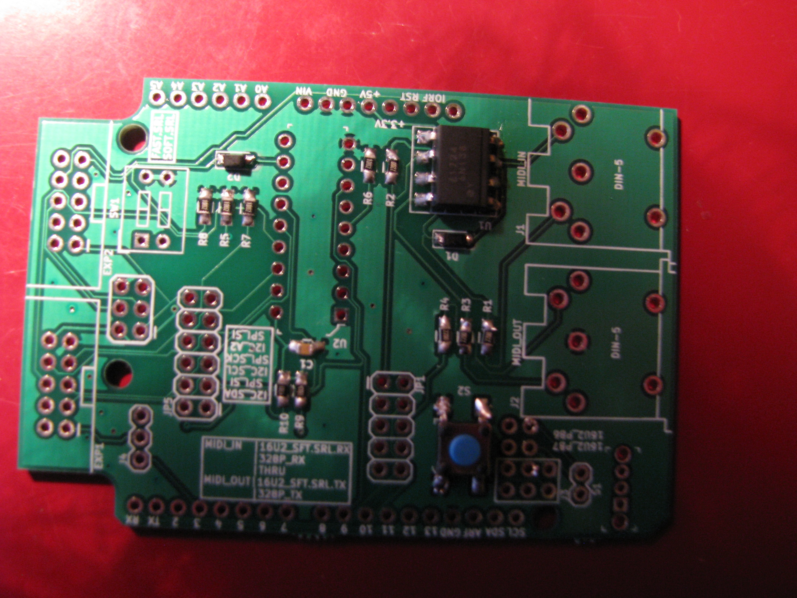
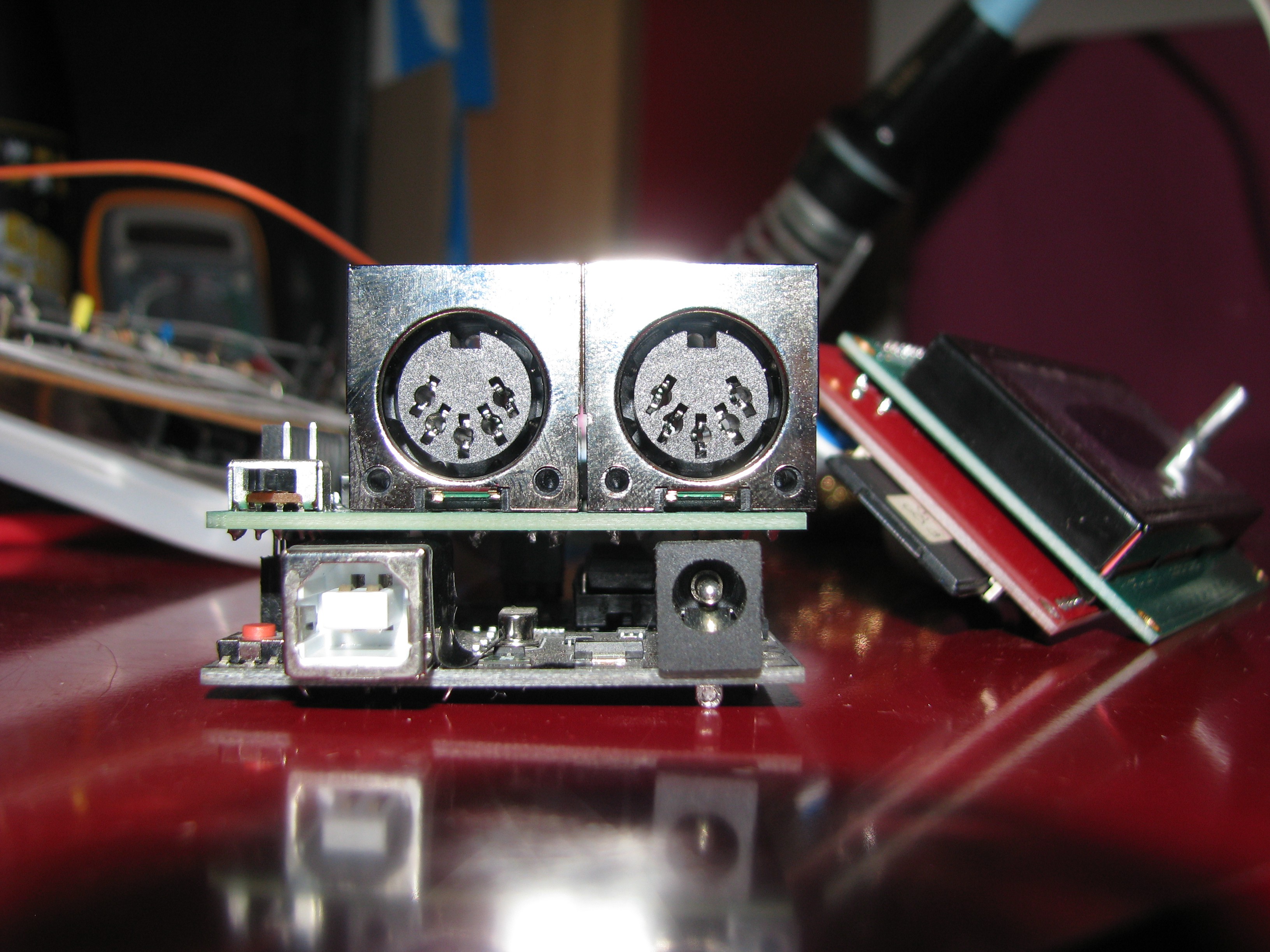
04/23/2018 at 13:21 • 0 commentsI slowly put together the first board I got today. For my first electronic design effort, I don't think it's bad. It's far from being perfect, but I didn't find any shorts, nor have I found gross inaccuracies.
That was my first attempt soldering SMT parts. It's not a very good looking job, but it wasn't that difficult.
![]()
You can probably see in the picture above that the optoisolator doesn't sit quite right. I should have thought of this when I used ready made footprints. the same thing goes for the DIN-5 jacks, as you'll see in the next pictures. I used a ready made footprint since that was easier, then got a different part from DigiKey. That's not that bad, but I should have checked beforehand.
![]()
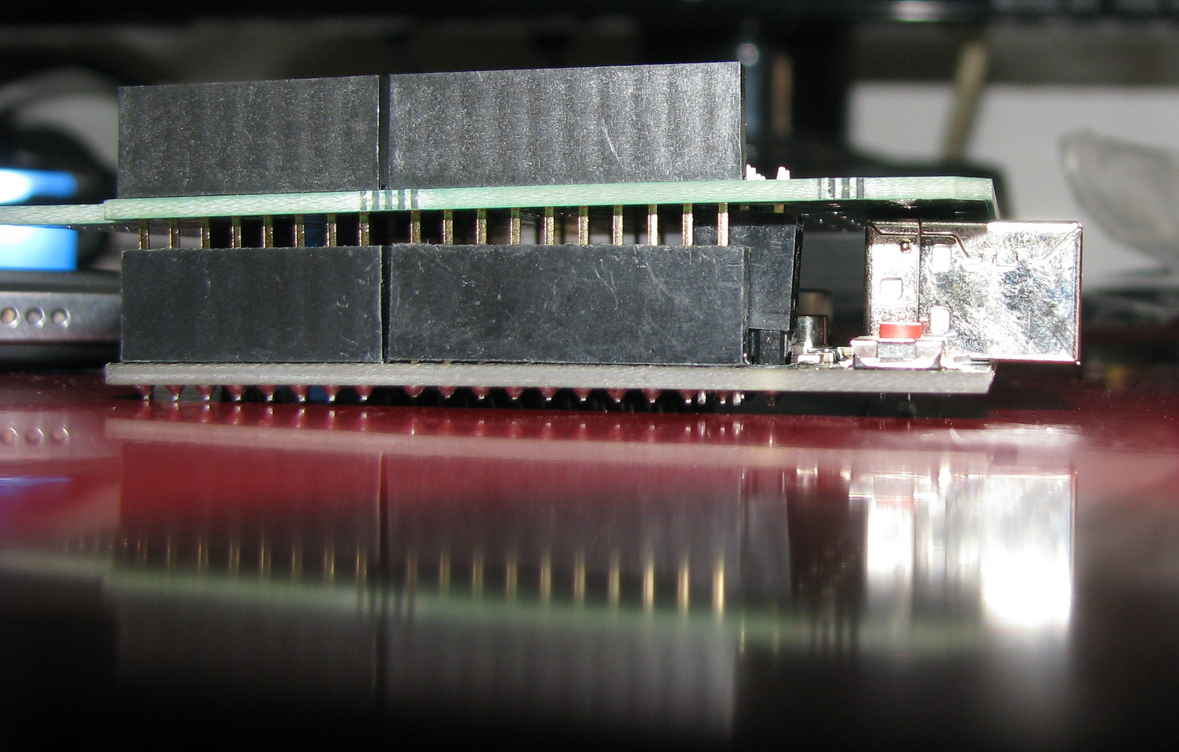
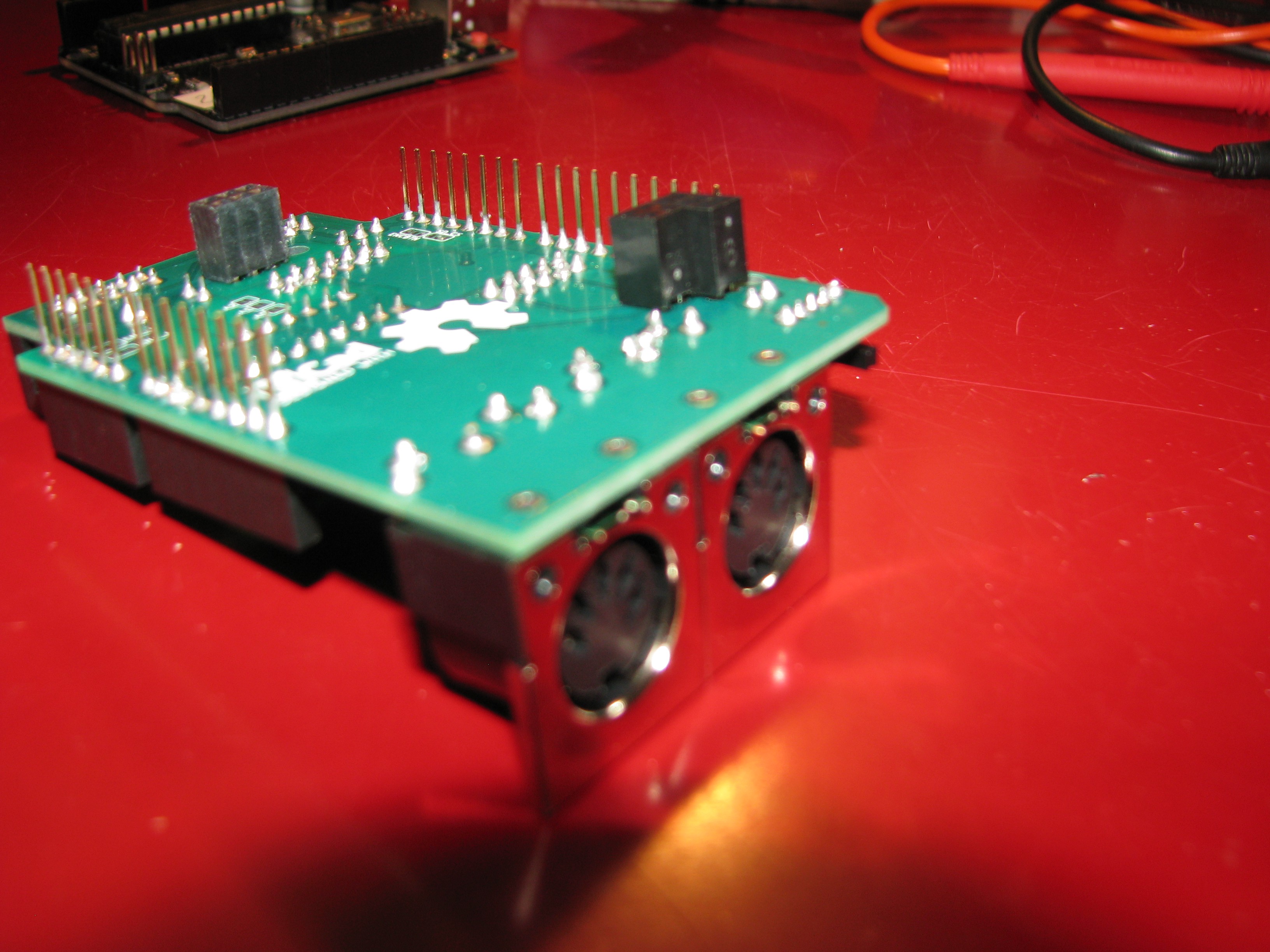
I also got a bit of a misalignment on the Atmega16u2 ICSP. Slanting the 2x headers a bit solved that. The board goes in and out as any other shield.
![]()
![]()
![]()
I started testing the board, but couldn't get the LCD to run. The encoder works, and I still have to do some testing on the SD and buzzer. I'll carry on with testing the LCD with both the MCP23008 & MCP23s08 tomorrow, and hopefully get the screen running so that I can go on with designing block in Ardublock.
-
PCBs and parts arrived!
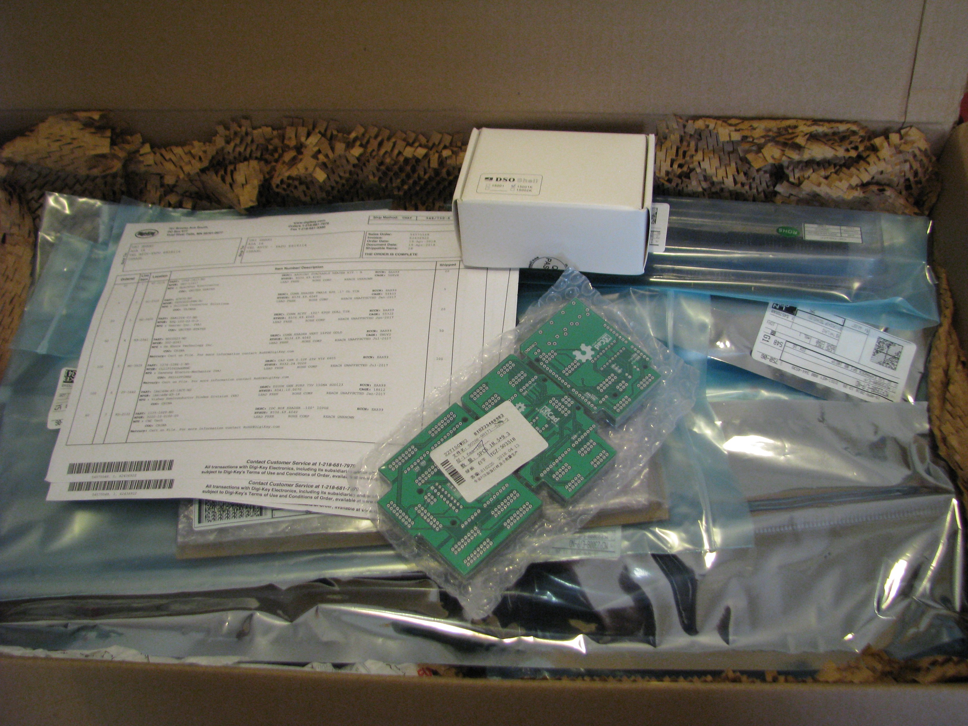
04/22/2018 at 15:57 • 0 commentsThe boards and components arrived today!!!!!11 YAY!!!!!11
![]()
The packaging was great, in the box I got from DigiKey everything was labeled, and the PCBs look great (to my untrained eye).
I also received a Jyetech osciloscope kit in the package I got from Elecrow, which I used to train on soldering. I couldn't find any shorts, but for some reason the control rotary encoder only works one way. I'll email them about that later - but right now, I _really_ want to build and test the UI PCB!
I actually got 7 boards instead of the 5 I ordered, so I hope even if something goes wrong I'll still have enough to fix that.
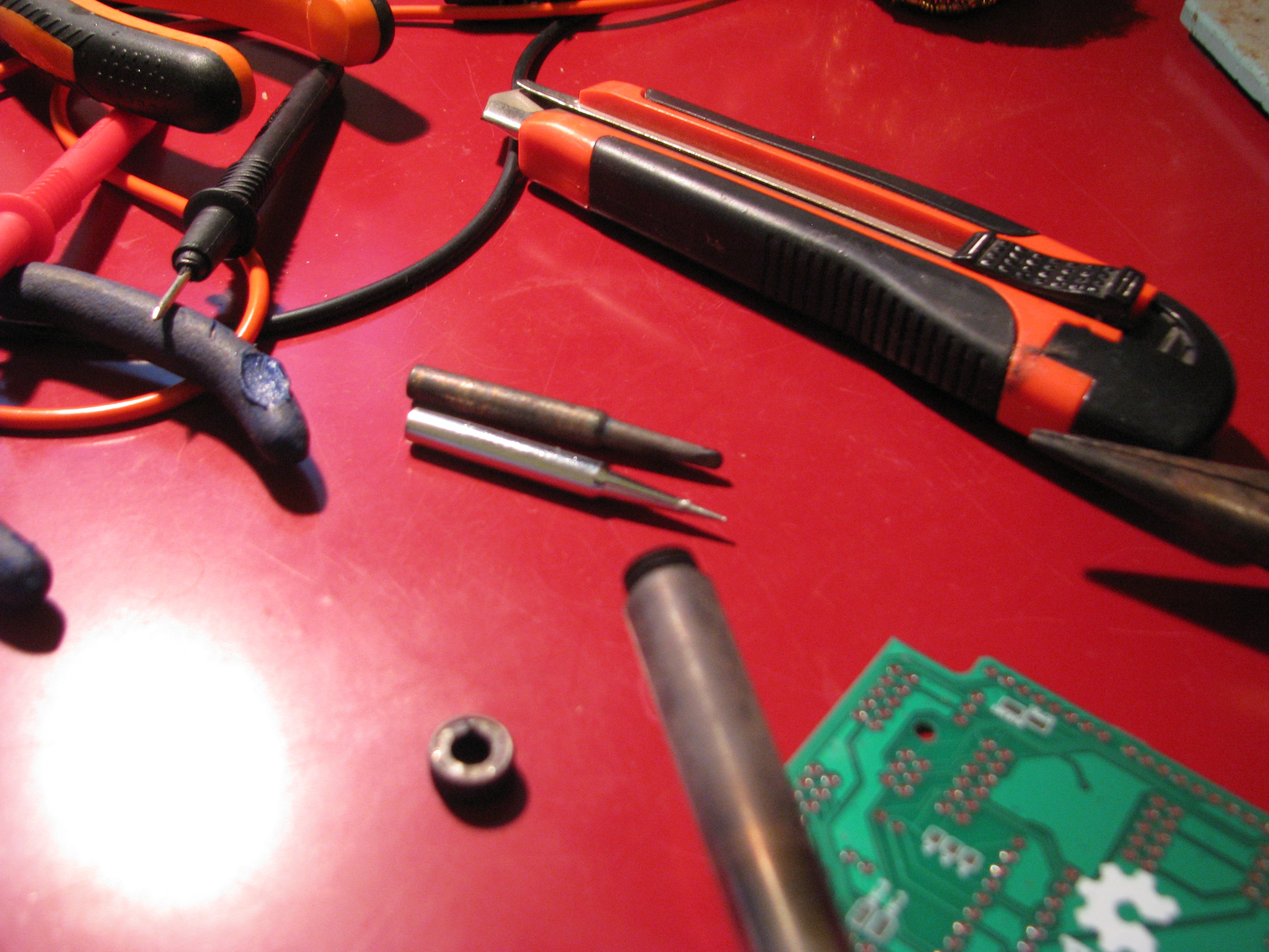
I also got some replacement tips for my OLD iron. I'm using an old Weller WP25 I got from some guy who cleaned his old storage, and really needed a new tip for the tiny 0805 resistors (I've never soldered SMT parts before). You can see why I needed the new tip in the pic below. The old one is just _so_ corroded. Anyway, I'm going to get things done!
![]()
-
UI Shield: making progress, software wise
04/20/2018 at 12:10 • 0 commentsI finally had some time to work on the software side of things in the last few days. I modified the OpenMoCo Menu Manager to work with a rotary encoder, and got it working today displaying a menu for my other project the Tannerino. I've uploaded the modified library to my Github account, and hopefully by Sunday I'll upload a concise example for using it.
I decided to go with the PinChangeInt library and not with the SCoop library, as I'm trying to make the code base for the whole system more concise. I plan on adding a 4 rotary encoder shield, which will probably depend on an additional microcontroller, and I believe getting 4 encoders deciphered will work better with an interrupt based system.
Since I'm waiting on both the boards and the PCBs (which should both be here by sunday), I'm using a '595 for bitshifting the characters to the LCD. When I'll get the MCP23s08 I'm going to modify Adafruit's version of the LiquidCrystal library to work with either an MCP23s08 SPI, 74xx595 SPI, as well as (the already written) MCP23008 I2C. I'll probably have to get an Arduino Mega as well, and configure the library to work in parallel mode with the RepRapDiscount Smart Controller Mega breakout.
-
LCD block design challenges: library selection
04/13/2018 at 10:38 • 0 commentsIn the last few days I was getting the software components for the first Ardublock I plan on coding. This first block will enable users of the UI shield to plan and execute a simple menu system on the 20x4 LCD, which is part of the RepRapDiscount Smart Controller, and also to navigate said menu with the on-board rotary encoder.
First, let me explain my choice of UI controls. The RepRapDiscount Smart Controller is commonly used in DIY (and commercial) 3D printers, and is quite easy to come by because of this. It also has a nice set of features: it has a 20x4 textual LCD (there's a graphic version as well), has a rotary encoder with button, an SD card, and a buzzer, all of these come on a ready to connect board with two ribbon cables and a breakout to connect the board to an Arduino Mega. This seems to me like a good candidate for the plug-and-play usability I am after in this project. This also served as an inspiration for connecting up sub-boards to make up a MIDI controller.
I am planning on using the "OpenMoCo Libraries for AVR" menu manager lib from DynamicPerception (Github). I've used this in the past, and it seems like it will be modular enough to provide me with the modular block-building ability I need for the Ardublock interface. I forked the OpenMoCo libraries, and will upload a version of the menu manager with a rotary encoder interface shortly (I already have this on my HDD somewhere).
Since I will be using ardublocks, handling of the encoder pin change interrupts will have to be done through SCoop, which I haven't dealt with yet - I checked out several pin change int libraries, and settled on PinChangeInt, but there are already SCoop blocks available, so hopefully block design will be simpler.
When trying out the design and seeing what blocks are already programmed, I accidentally erased the sketch I was working on. I need to find out if there's a way to combine an existing sketch with ardublock code. If there is no way of doing so, and some Arduino fork of Blockly will be a better candidate, I might prefer this route. the whole idea of programming the board in a block-based gui is to make people more familiar with the idea of programming, so giving the users the ability to change manually certain aspects of their program is important to me. If you read this and know if any of the block programming languages offer this ability, please let me know.
I also found two faults in my design of the UI shield. When going through my design before sending it to the fab house I found that I forgot to place the two 4k7 pullup resistors on the I2C lines. I'm using Adafruit's LCD Backpack as one of my reference designs, and also plan on using Adafruit_LiquidCrystal as it's already set up to use Adafruit's own MCP23008 lib. I found out that I changed the LCD pins from 1-7 to 0-6. The resistors were put in place before I sent the designs, but the pins will need to be changed on the next revision.
I also found a port expander library which has both MCP23s08 & MCP23008, but haven't had the time to explore it much yet.
-
Rethinking viability
04/10/2018 at 18:46 • 0 commentsI ordered the demo boards today from ELECROW. I went through finalizing the panel and making sure all my design rules were correct and there were no stray ground plane artifacts. While I already had the cost estimates, I re-thought the value of the modularity of having shields which connect to pots, buttons, etc.. It makes building a MIDI controller quite expensive if one needs to have an Arduino, a MIDI / mocoLUFA shield, and an additional shield for analog MUX or a digital matrix, plus pots or buttons or what have you. And you still need to have cables to connect peripherals to the shield. So I think I'll do some re-evaluation of cost, starting with available cables and smt cable connectors to match. I also think that the next iteration of the shields should have a single board for both SPI and I2C, but in a different configuration. Currently, the SPI / I2C selection (based on pin compatibility of MCP23S08 and MCP23008 port expanders) is designed to be done through manual jumper selection, and the port expander can be replaced, as it's spec'd as 18-DIP in a socket. A much lower cost alternative will be to have to have the port expanders as smd parts, selectable only in manufacturing, and having two solder stencils - one for SPI, and the other to bridge connectors and get I2C. A third, kind of compromise, option will be to have the port expanders placed in a smt DIP socket, and the jumpers either as smt DIP switches. Further still, having the port expander in a smt socket while having the SPI / I2C jumper selectors as pads on the board can further reduce cost, while still allowing future flexibility. This is maybe more fitting to the goal of having this system address novice users, since I think most such users will not want to decide whether to go with this protocol or the other, just something that works. Having the chip in a socket and having pads as jumpers still means future compatibility for users who outgrow the use of stock option. I'm currently leaning towards SPI as the main protocol as it's a lot faster, but waiting on the boards to test the usefulness. I'll probably have to design some breakout boards for pots and a button matrix to test the first boards anyway.
Arduino Blocks for MIDI Controllers
A series of typical MIDI-event-oriented *duino shields, accompanied by graphical programming blocks that are MIDI specific.