frankstripod
-
Mouse Update
06/04/2015 at 11:28 • 4 commentsMy mouse still works great and I use it often, but it has been stripped down for parts my in my Driverless Mouse Project. For now its just the trackball, left and right buttons. It looked really sad for a mad scientists mouse, so I want to cheer it up a bit.
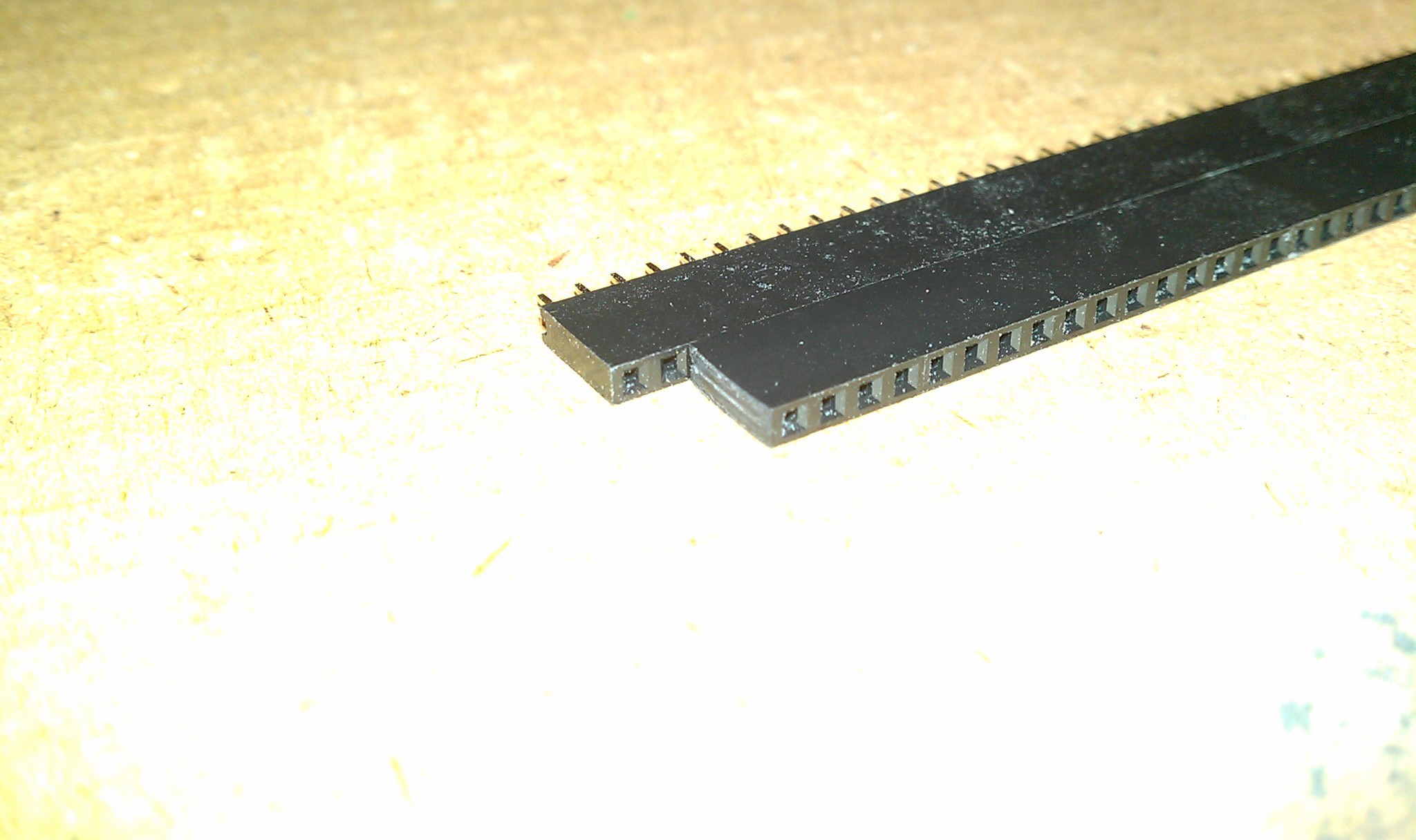
Taking the left cover off completely, I held it up to the light, and I had seen this before but ignored it. The holes in the headers make it semi transparent, like a screen:
Then it hit me; Nothing makes a hacker more happy than sticking some LEDs on something. Some RGB LEDs mounted underneath would shine up through the top and cheer it up for sure.
It will be like Frankenstein Mouse meets 70's Mood Ring. More on that when I get some more parts and LEDs from other projects.
-
Fork in the Road
08/26/2014 at 22:11 • 0 commentsUpdate:
I use the trackball and the LED screen sharing feature everyday as my main input device with no problems. So finishing this project is important to me because I really want one of these now.This project will probably split into two or more projects:
1. The New Device: Driverless Mouse and Keyboard Sharing.
2. My trackball project (here)
3. Other controllers.Details and further development for the Driverless Mouse and Keyboard Sharing:
https://hackaday.io/project/2872-Driverless-Mouse-and-Keyboard-Sharing
:
Side notes:
The three computer system and my desk will be dismantled, and the project is going on the road with me. Project logs may be slow, please be patient.
-
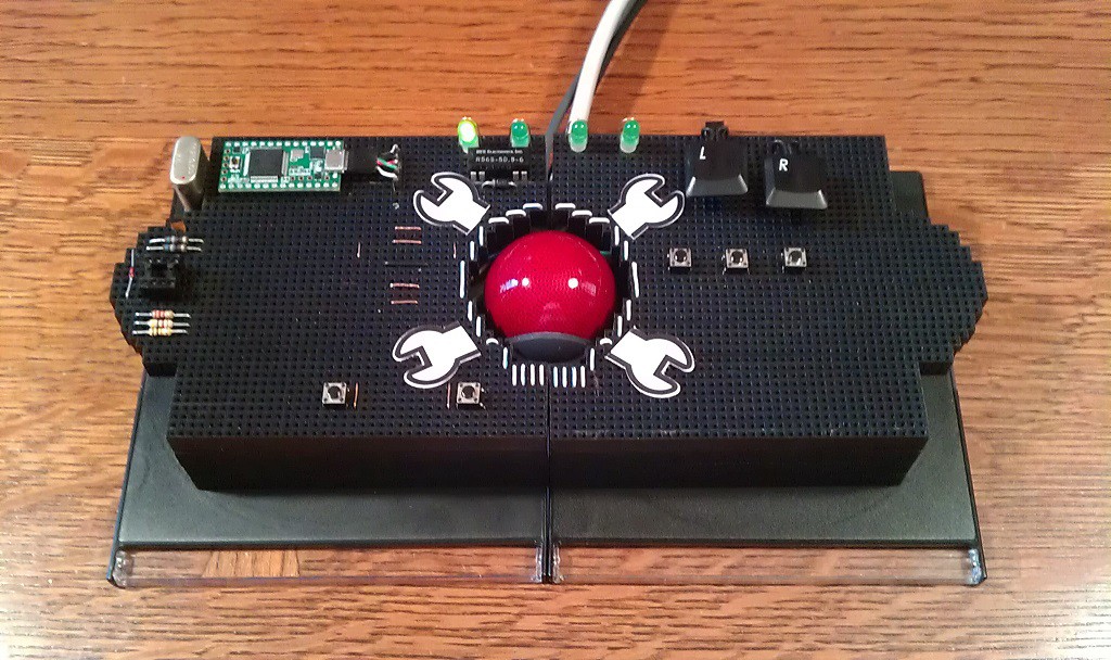
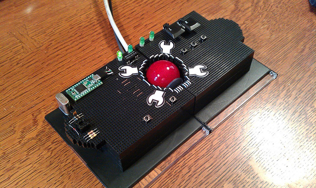
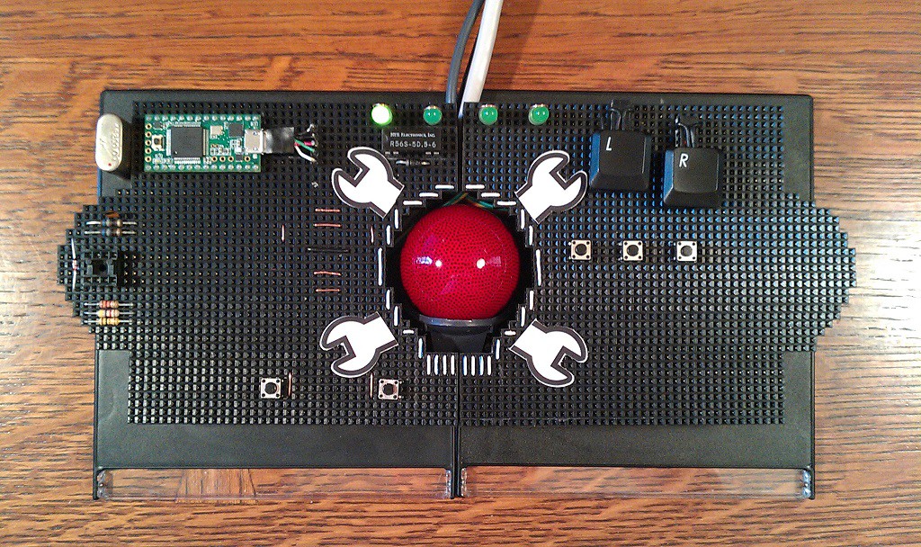
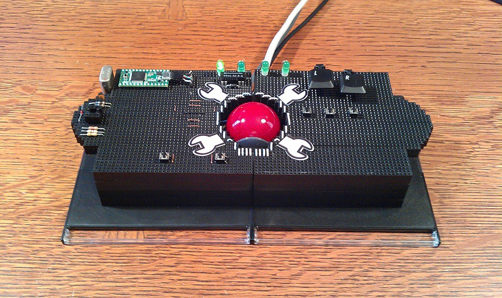
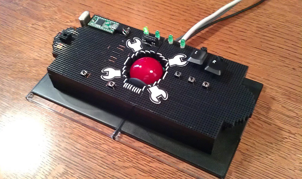
A 100% Hacked mouse.
08/26/2014 at 08:25 • 0 commentsPhase 1: Complete! I built a 100% Hacked mouse.
Ingredients Hacked:
1 Teensy 3.1 Microcontroller. Hack: Chopped together code from Arduino Examples.
1 Logitech Trackball Marble Mouse. Hack: Gutted and reused inner working parts.
100 Female Headers. Hack: Not intended for circuit board-less artsy super glue project.
1 Belkin Four Port USB Switch. Hack: Amputated and rewired LED's and switch.
1 Targus Four Port USB HUB. Hack: Tapping off common power supply.
7 USB Wires. Hack: One cut for power, others in sets of 3 three piggybacked end to end.
1 Cat-5 Wire. Hack: Non-data use for LED's and switch.
2 CD cases. Hack: A temporary base.
My Favorite Features:
1. Its made for me! You probably hate it. I will hate it in two days because of the layout, but now I can't curse when I install the buttons in the wrong place, because I can move them in .100" (2.54mm) increments anywhere on the surface.
2. No Drivers, No Drivers, No Drivers: Also, ALL features work on ALL platforms without even a hint of drivers.
3. Capacitive Touch Mouse and Keyboard Sharing. An all hardware solution to Synergy* software. Shares the mouse across four computer screens on any platform. It also brings along the keyboard and USB hub for all four computers. Also helps passwords and private data from being transmitted over LAN or WiFi when compared to Synergy.
4. An excuse to put LED's on a mouse.
6. In-System Programmer: I always wanted an ISP, now there is one on my mouse, complete with a staging area ready for an ATtiny85, spare parts, and room to jumper to something larger like an ATmega328p.
5. Instant change of hand positions on to duplicate button patterns to reduce fatigue.
6. Four way capacitive touch sensor scroll pad.
7. Breakout Sockets next to pins for quick connecting. Teensy pins, USB power and data.
8. Programmable buttons, and application specific buttons.
9. Left Click drag lock; Press once to hold, again to release.
10. Ctrl Left Click; Open link in new tab.
11. Select All, Cut, Copy, Paste, Enter and Backspace buttons.
12. Ctrl Lock and Shift Lock.
13. Middle button (Sounds boring, but I never had one because of the devices I was using.)
![]()
![]()
![]()
![]()
![]()
-
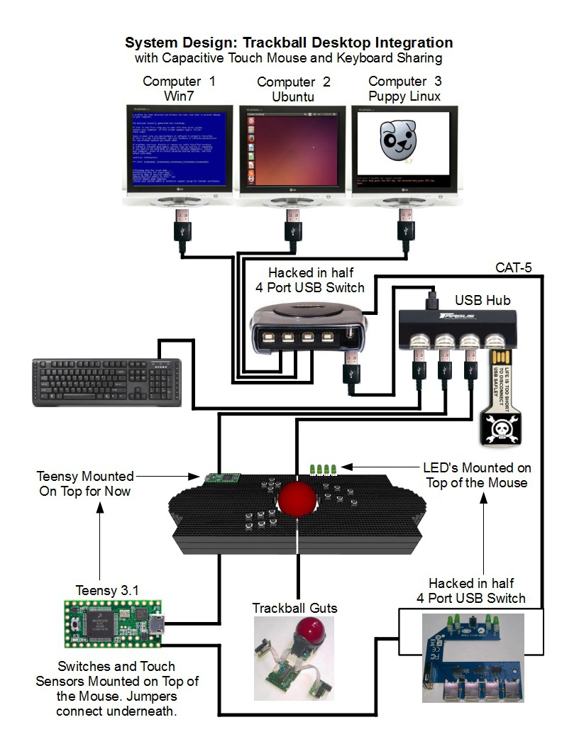
System Design
08/21/2014 at 03:29 • 0 commentsThere are two system diagrams. The first is the projects current working prototype:
![]()
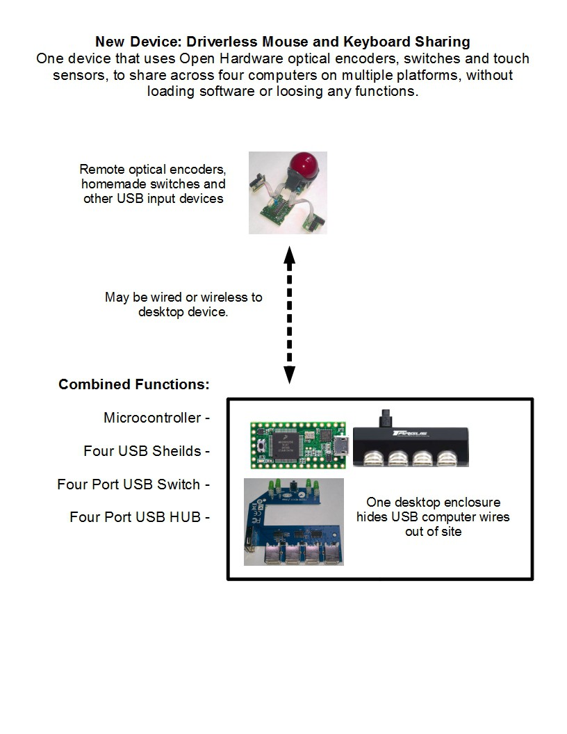
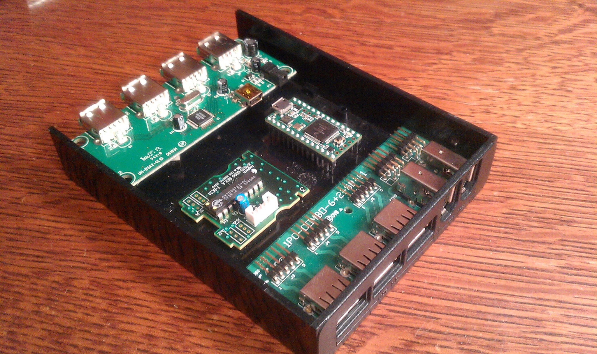
The second is the Open Hardware device I want to build.
![]()
The device needs a new name that accurately describes it.
Imaginary hypothetical image:
![]()
More info coming soon.
-
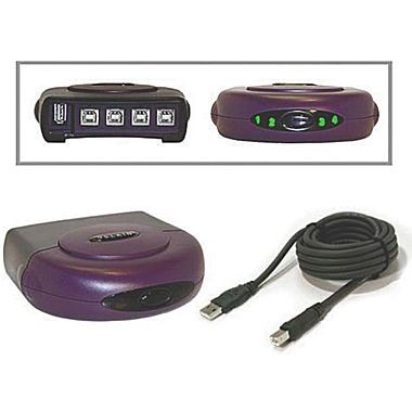
Synergy Mouse and Keyboard Sharing
08/21/2014 at 03:26 • 0 commentsCapacitive Touch Mouse and Keyboard Sharing:
I put the description first, then pictures and how I hacked it later.
The Teensy switches and manages a four port USB switch with four LED's and four touch sensor buttons
Synergy: Please visit and donate to synergy-project.org.
First I would like to explain my love and addiction for a program called Synergy. It shares a keyboard and mouse between multiple computers. One computer with a keyboard and mouse is set as a Synergy server, then other computers are added as clients and communicate over a local network. I love that its Open Source, multiplatform, and has a quick smooth transition from one screen to another.
Synergy dislikes:
- Its network dependent so any computer or router with a hint of connection problems fails.
- All client keystrokes like passwords and account numbers go through the local network, although there is an option for encryption.
- Setup can be complicated with mixed platforms.
- It can not be used on screens where the client is disabled. For example; BIOS setup, Windows user account control, live CD's, some network passwords and user logins.
How its hacked:
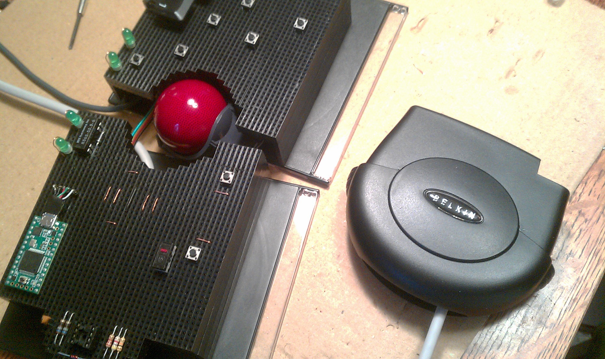
I purchased this four port USB switch years ago to avoid the aggravation of swapping USB plugs every time Synergy disconnected.
![]() I hacked
the USB switch into a hardware solution by having the Teensy
Microcontroller do the switching for me.
I hacked
the USB switch into a hardware solution by having the Teensy
Microcontroller do the switching for me.It originally worked by pressing the only switch, which increments the port number by one, and back lights the port number LED.
Inside:
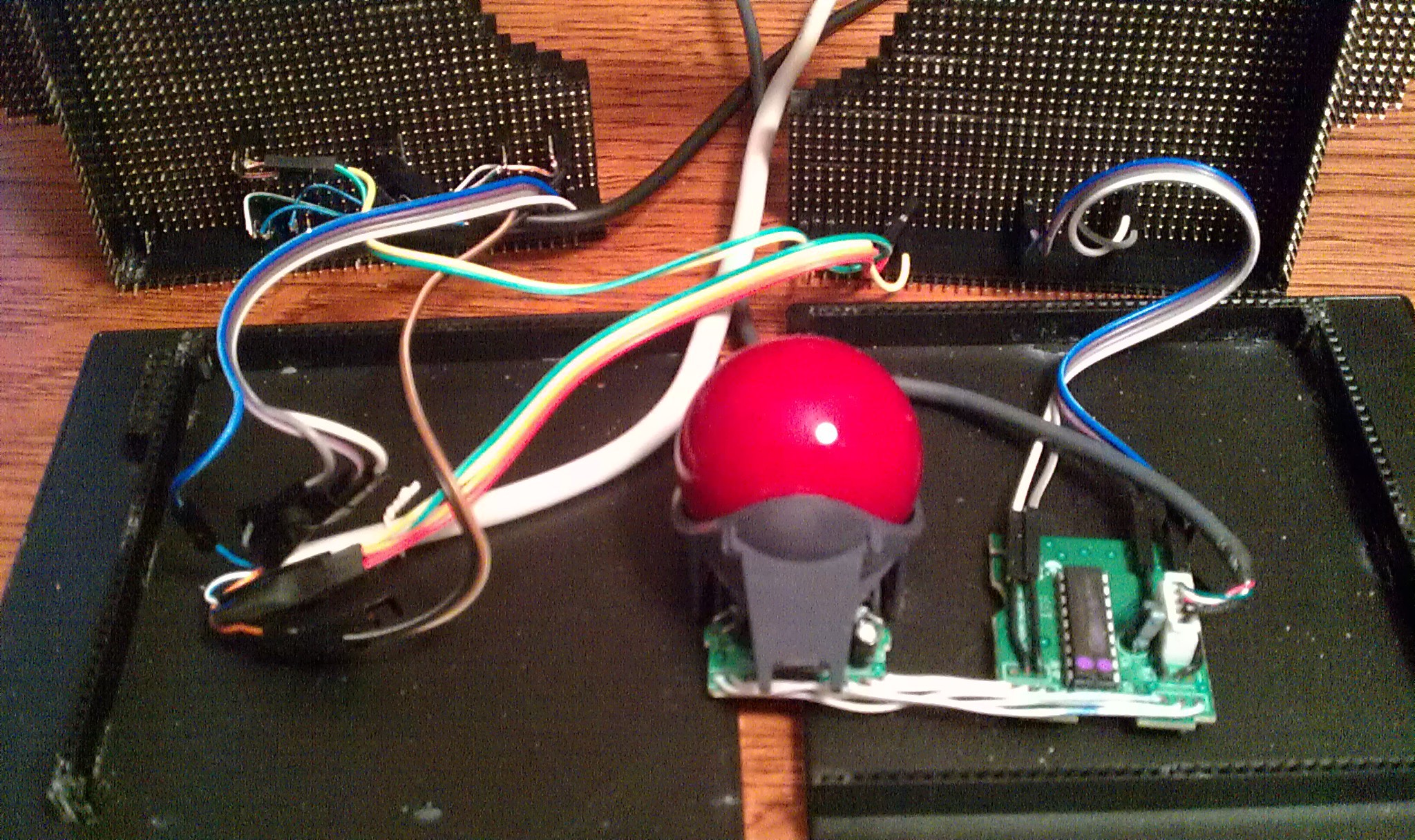
![]() If you cut the board in two, I would want the lower half behind the desk, out of sight with all the wires. The upper half looks like it needs a hacking onto the top of my trackball!
If you cut the board in two, I would want the lower half behind the desk, out of sight with all the wires. The upper half looks like it needs a hacking onto the top of my trackball!Desoldered the LED's.
![]() I tested the circuit with a multimeter and the wiring was confusing at first because the left pair of LED's connect anodes to ground, and the right pair connect cathodes to the same ground. To keep it simple, and to utilize the built in resistors...
I tested the circuit with a multimeter and the wiring was confusing at first because the left pair of LED's connect anodes to ground, and the right pair connect cathodes to the same ground. To keep it simple, and to utilize the built in resistors...![]() ... I kept the circuit the same through the CAT-5 wires:
... I kept the circuit the same through the CAT-5 wires:Each pair of LED's gets three wires: LED#1+, LED#2+, common pair ground.
Plus two to short the switch underneath.
![]() Homemade two pin female jumpers made from two pin headers.
Homemade two pin female jumpers made from two pin headers.Common ground wires matched in pairs.
![]() Back in its shell. Cable runs through missing LED hole, strain relieved by a cable tie on the inside.
Back in its shell. Cable runs through missing LED hole, strain relieved by a cable tie on the inside.![]()
A USB switches' worst nightmare...
![]() ... and kept alive to see its own working LED's amputated and transplanted on my track ball.
... and kept alive to see its own working LED's amputated and transplanted on my track ball.![]() The wire on the third LED is a hacked experiment for touch sensors on LED's.
The wire on the third LED is a hacked experiment for touch sensors on LED's.Desktop integration on three computers:
![]()
Cable restrained to the base. The more flexible wire female jumper wires connect to the solid wire, then taped.
![]() Then plugged directly underneath the transplanted LED's
Then plugged directly underneath the transplanted LED's![]() The third jumpers connect under the touch sensor wires.
The third jumpers connect under the touch sensor wires.Connecting the Teensy:
![]() I used an NTE R56S-5D.5-6 reed relay: (5v, 3.8v min), and a "flyback diode." The relay does not have a built in diode. (the "R56S-5D.5-6D does; that first "D" is tricky. NTE_R56_57specs.pdf )
I used an NTE R56S-5D.5-6 reed relay: (5v, 3.8v min), and a "flyback diode." The relay does not have a built in diode. (the "R56S-5D.5-6D does; that first "D" is tricky. NTE_R56_57specs.pdf ) Thanks to the PJRC forums for the information on the flyback diode saving the Teensy from sure death from the relays coil. Next time I will get the ones Paul recommended;
http://forum.pjrc.com/threads/23693-Baisc-Teensy-2-is-the-switch?highlight=9007-05-01
http://www.digikey.com/product-detail/en/9007-05-01/306-1063-ND/301697
The NTE116 (1N4004) diode and the relay were in stock at my small local electronics store.
Jumpers made from two pin female headers and solid strand wire:
![]() The two header sockets have the wire insert 3mm pin fix. The two male pins are bent together into a two pin jumper, and then soldered to the wire. This connects the relay to the diode in parallel. See relay pins pictured above.
The two header sockets have the wire insert 3mm pin fix. The two male pins are bent together into a two pin jumper, and then soldered to the wire. This connects the relay to the diode in parallel. See relay pins pictured above.![]() Two pin jumpers relay to diode:
Two pin jumpers relay to diode:![]()
Two pin jumpers on the Teensy side make for easy access breakout sockets on top.
![]()
The code for the Teensy is simple:
See which LED is being touched, figure out how many steps from the current port to the desired one with some simple math, then send that many long delay pulses to the relay. The coed is below and needs to be cleaned up. I was trying to blindly integrate variable names. The delays were easy to figure out by "higher/lower" testing for speed and consistency.
I triple checked the connections before connecting the Teensy. It turns out the relay sends an unknown (to me) signal to the USB switch moving it backwards (decreasing); so I just reversed the formulas in the code to work backwards.
Wish List:
Making an Open Hardware trackball with optical encoders, controlled by a microcontroller, that traces mouse movements to calculate each computers mouse pointer position (without drivers). That will allow for screen edge detection and gestures for smoother faster screen transitions, eliminating the need for the touch sensors.//
//
/* Mouse Controler Project 2014 @ hackaday.io by frankstripod via Teensy 3.1
*/
// Touch USB switch setup:
const int u = 4; // Number of USB touch sensors used
int upin[u]={0,1,22,23};
int ubase[u];
int usb[u];
int unow=1;
int utouch = 1;
int relay = 0;
int relaypin = 3;
// Touch sensor adjustments:
int sensitivity = 130;
int touchDelay = 100;
int Delay = 100;
int c; // Generic counter
int led = 13; // Blink conformation
void setup() {
Serial.begin(38400);
for (c=0; c<u; c++) {
ubase[c]=touchRead(upin[c]); // Baseline calibration
}
pinMode(led, OUTPUT);
pinMode(relaypin, OUTPUT);
}
void loop() {// Read the sensors
utouch = 0;
for (c=0; c<u; c++) {
usb[c] = touchRead(upin[c]);
if (usb[c]-ubase[c] > sensitivity) {
utouch = c+1;
}
}
// Skip the rest if nothing is touched
// Figure how many steps
if (utouch) {
relay = 0;
if (utouch > unow) {
relay = 4 - (utouch - unow);
}
if (utouch < unow) {
relay = unow - utouch;
}
unow = utouch;
// Pulse relay that many times
for (c=0; c<relay; c++) {
digitalWrite(relaypin, HIGH); // increment +1
delay(10);
digitalWrite(relaypin, LOW);
digitalWrite(led, HIGH);
delay(100);
digitalWrite(led, LOW);
}
}
} -
ISP and Retro Crystal
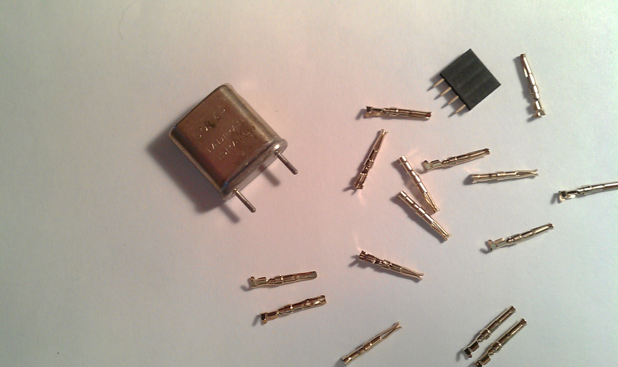
08/21/2014 at 03:15 • 0 commentsA funny thing happened when I walked into my favorite local electronics store.
I asked for the impossible 3mm pin connectors. They gave me the smallest socket inserts they could find in the store, They didn't work, but I took them anyway thinking I could crimp or modify them later. (That didn't work.)
Then I asked for an ATmega328p and a 16MHz crystal for programing it. They didn't have the ATmega in stock, but came back with this:
![]() Its an old style crystal from an old amplifier (I think). I wouldn't think of mixing old tube style components with newer 3.3v logic, but when I saw it, I knew it was going to give my trackball the retro feel it was needing to make it even more artsy. Then later I found out those pin inserts actually made a perfect socket for it.
Its an old style crystal from an old amplifier (I think). I wouldn't think of mixing old tube style components with newer 3.3v logic, but when I saw it, I knew it was going to give my trackball the retro feel it was needing to make it even more artsy. Then later I found out those pin inserts actually made a perfect socket for it.![]() Deadbug Style!
Deadbug Style!![]() With headers of course.
With headers of course.![]() The alligator clip test lead is pointing to the two sockets to the crystal.
The alligator clip test lead is pointing to the two sockets to the crystal.I don't know if its even possible to use this. Any ideas? I will need to thoroughly test and research this before using it. I just think it looks cool.
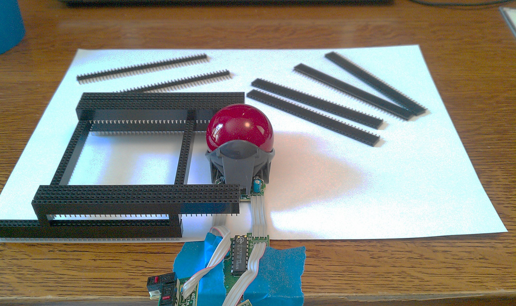
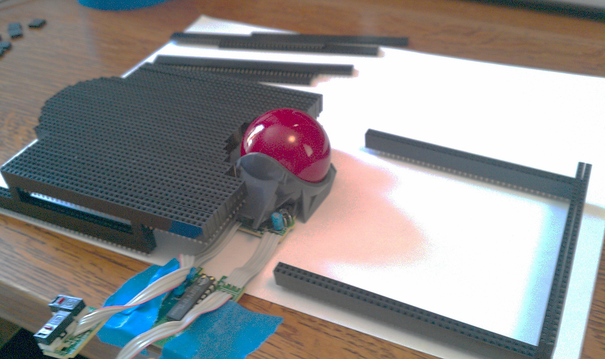
The platform on the end is almost ready for programing an ATtiny85; with room for spare parts!
:
:
In-System Programmer: Finding this was like a dream come true
http://arduino.cc/en/Tutorial/ArduinoISP
http://arduino.cc/en/Tutorial/ArduinoToBreadboard
My trackball was made for this!
To be honest, I mounted the Teensy 3.1 on top of the mouse just because I thought it would look cool, but now realize having access to all the pins allows me to share it with other projects. A second solderless breadboard and a few jumper wires start an experiment in minutes, or I can skip the breadboard and test a component right on top of the mouse itself. Every pin on the Teensy will be connected underneath to its adjacent socket on the top of the mouse, so a male jumper wire connects in seconds. Uploading and rebooting sketches for other projects does not mean full loss of the mouse because the Logitech chip still handles the trackball and both the right and left backup buttons, so I can program an ATtiny85 and surf at the same time without switching cables. Also, the mouse and keyboard sharing feature has a mechanical USB switch fall back mode with a tactile switch, and still works with the keyboard or even a second mouse, when loading sketches.
-
Jumpers and Switches
08/21/2014 at 03:13 • 0 commentsConnecting Teensy:
It would have been typical for me just to plug a standard cable on top of the Teensy and say "there, I fixed it!" But I wanted this to be integrated into the design. The goal here is USB for Teensy, and breakout pins on top.
I don't know why I did this this way but this is how it went. Five wire USB cable chopped.
![]()
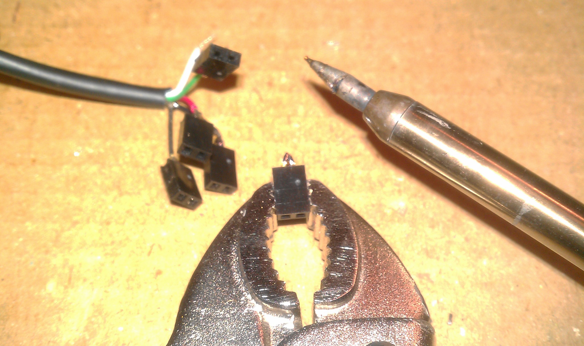
Two pin header pins bent and soldered. Each two pin jumper splits each wire; one for Teensy, one for a breakout connection on top of the trackball.
![]() 5x
5x![]() Two pin header sized squares of electric tape between each.
Two pin header sized squares of electric tape between each.![]() All five super glued together (held in position with two male header strips not shown.)
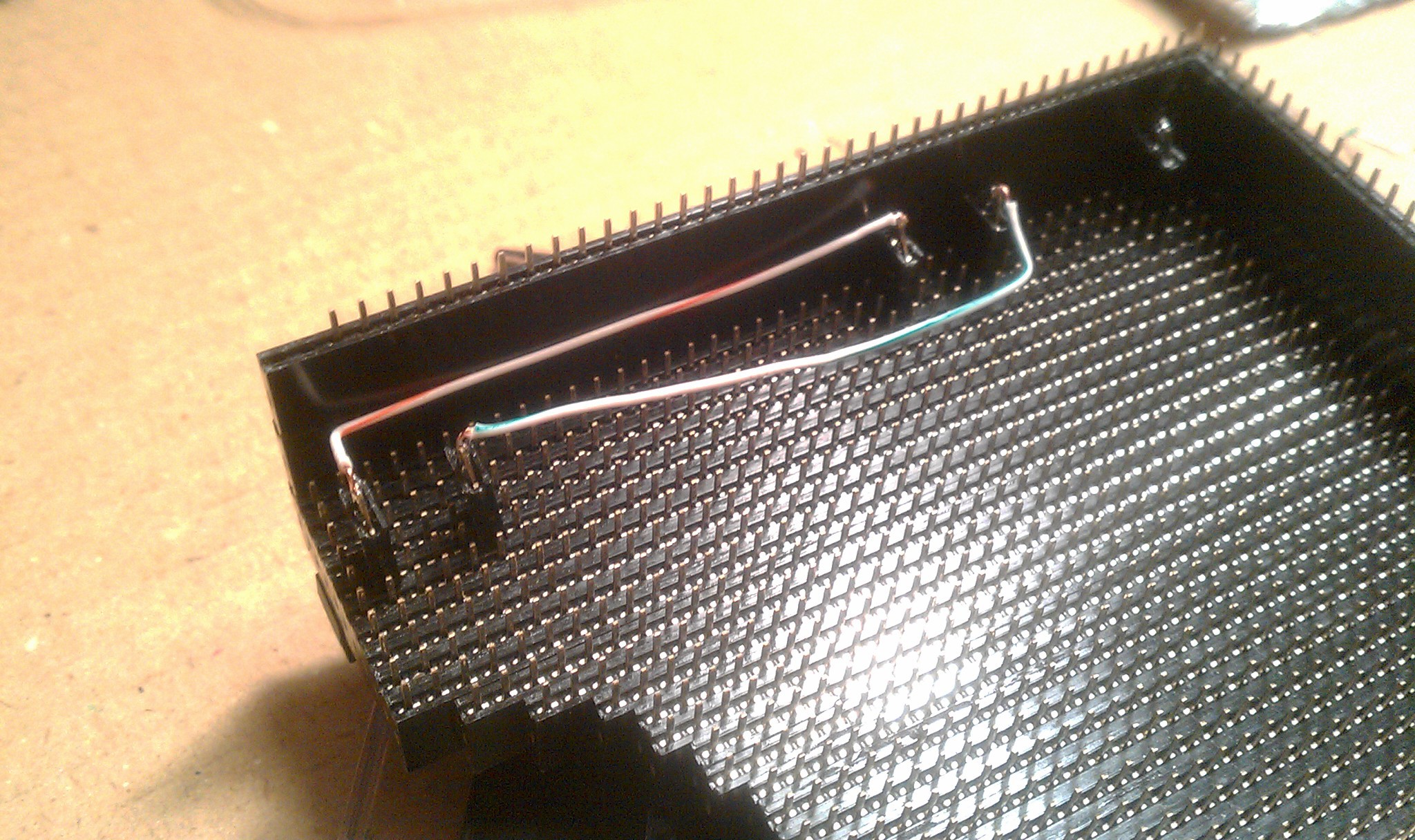
All five super glued together (held in position with two male header strips not shown.)A rectangle of super thin clear plastic cut from the recycling bin glued along the side for support. Homemade connector:
![]() Plugged in underneath.
Plugged in underneath.![]() On top I chopped an old USB micro cable for its connector. I had to be careful not to bend the delicate wires barely held on with glue. Soldered to a five pin male header, plugged into place.
On top I chopped an old USB micro cable for its connector. I had to be careful not to bend the delicate wires barely held on with glue. Soldered to a five pin male header, plugged into place.![]() Each pin is duplicated to its corresponding female socket.
Each pin is duplicated to its corresponding female socket.![]()
:
:
:
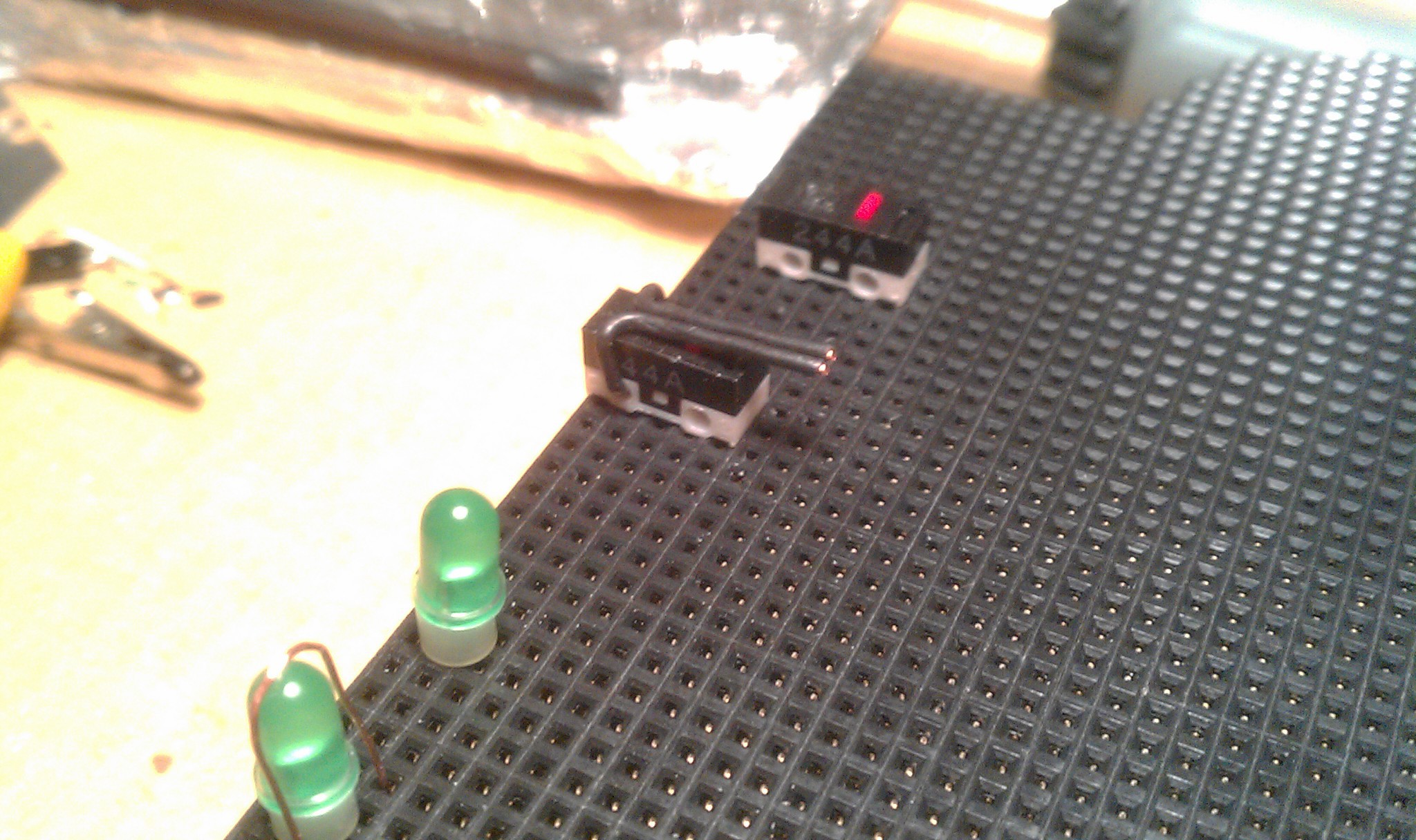
Secondary left and right buttons:
There are the desoldered mouse switches. 20 gauge solid wire with black insulation was used as a lever.
![]() Then keyboard caps L and R were pried off of an old PS2 keyboard. The wire wrapped around the bottom, making a telegraph style button. Supper light touch and slightly flexible, but defiantly needs something like a 3D printed upgrade.
Then keyboard caps L and R were pried off of an old PS2 keyboard. The wire wrapped around the bottom, making a telegraph style button. Supper light touch and slightly flexible, but defiantly needs something like a 3D printed upgrade.![]()
:
:
:
Another possible layout.
![]()
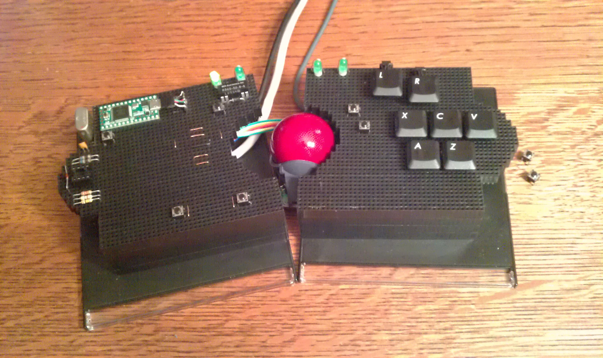
The split design conforms to my hand real well.
Touch sensor scroll wheel is back (just left of the trackball).
:
:
:
No PCB :(
You probably think I hate circuit boards. I don't. This project just turned out to be more artsy then most people are comfortable with. Not having one kept the height down; this is even slightly shorter than the original Logitech Trackball. In the back of my mind i'm subconsciously building version 2.0 which has a more solid design:
1. Circuit board holds female headers with extra long pins, soldered through the hole, then trimmed down to 7mm (6mm socket friendly + 1mm for solder).
-
Trackball Install
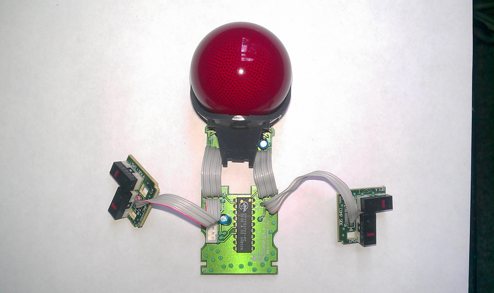
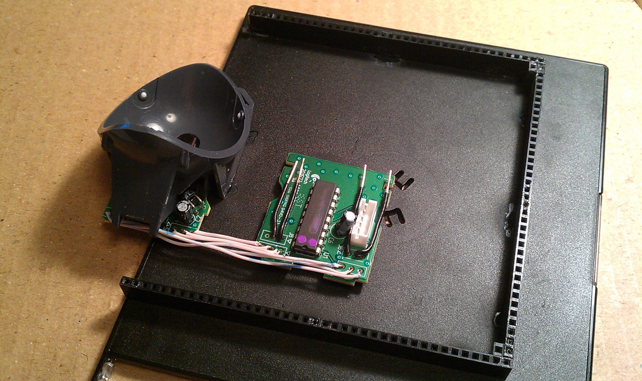
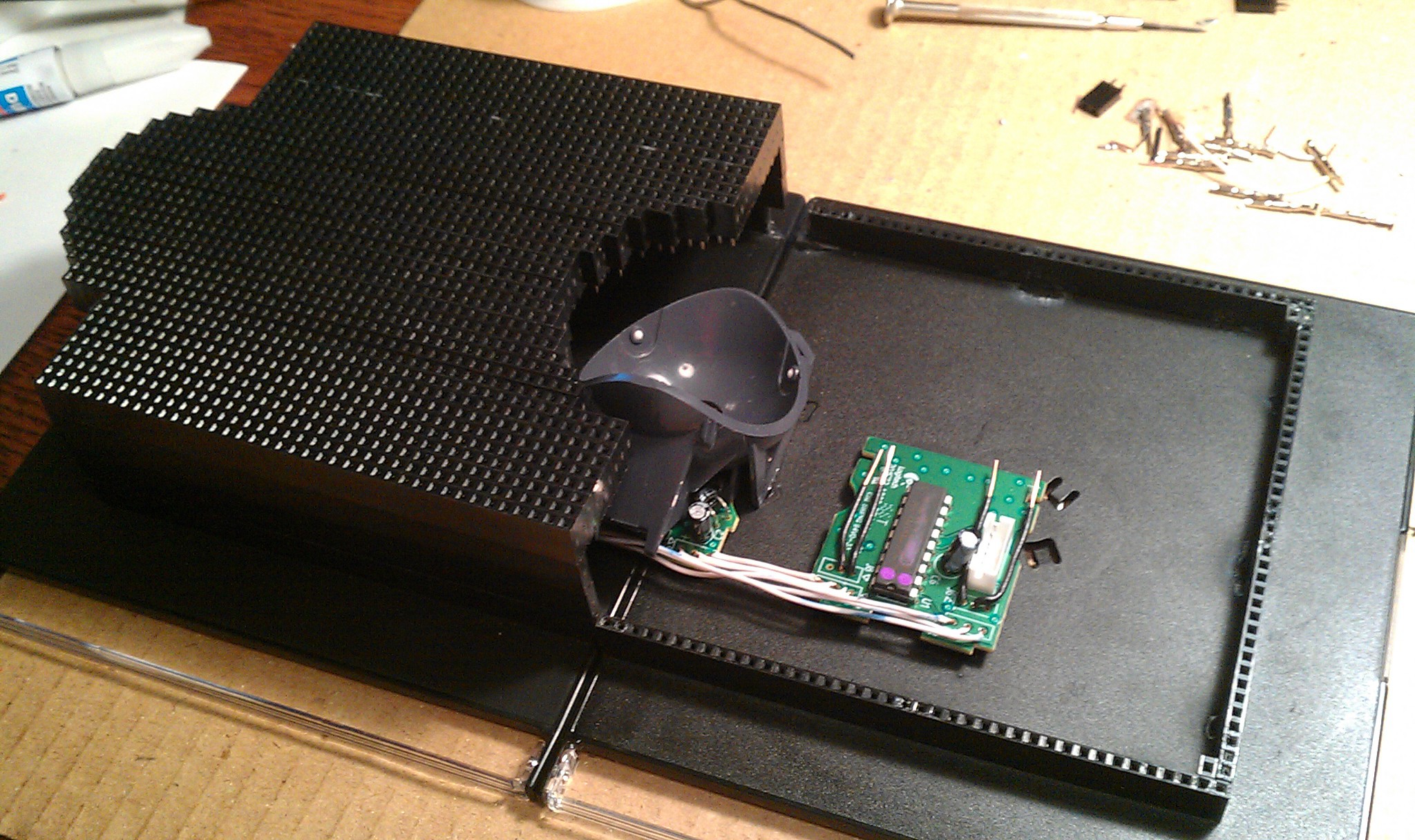
08/21/2014 at 02:06 • 0 commentsThis would not fit inside my trackball.
![]() Chopped
it, soldered it, hacked it.
Chopped
it, soldered it, hacked it.![]() Dead bug
style. I soldered the wires long through the holes to keep air space underneath.
Dead bug
style. I soldered the wires long through the holes to keep air space underneath.![]() The
black 20 gauge wires soldered on top work with the female jumpers. These are for backup left and right mouse buttons if the Teensy is disabled.
The
black 20 gauge wires soldered on top work with the female jumpers. These are for backup left and right mouse buttons if the Teensy is disabled.![]()
This was designed split in the middle for hand comfort, like a split ergonomic keyboard.
![]()
The right half gets the trackball.
![]() The first jumpers!
The first jumpers! ![]()
The first components on the board! The two mouse switches.
![]()
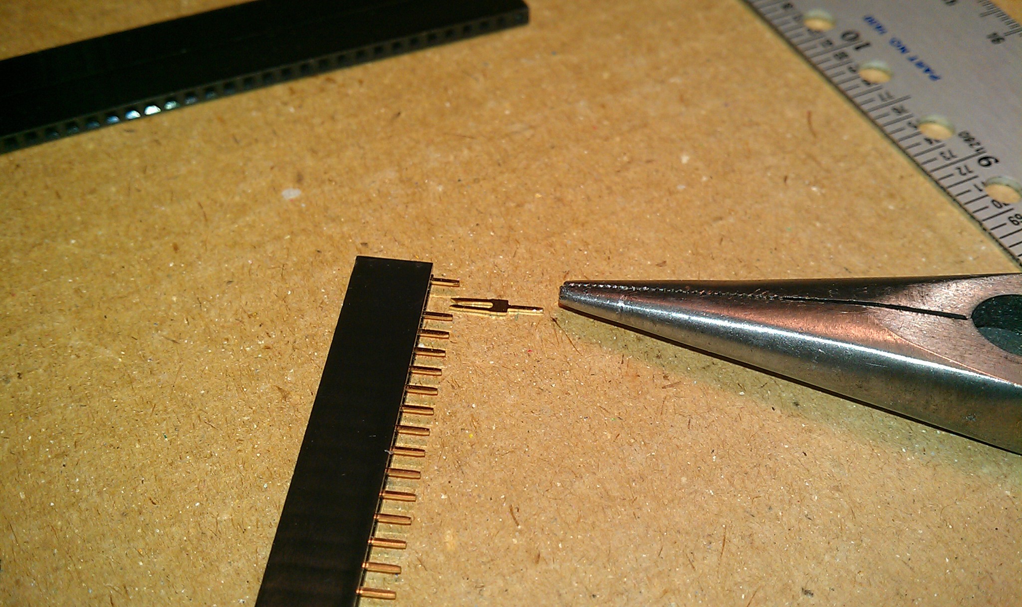
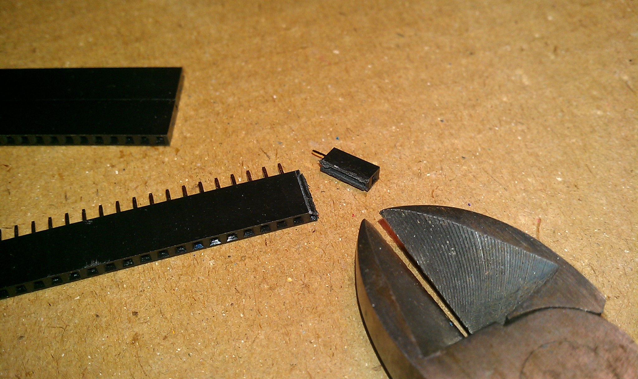
Remember the "3mm pin in 6mm socket" problem from the "Adafruit vs Futurlec Header to Header Grudge Match"? I found a simple solution. I inserted 24 gauge wire into the socket, cut it off even, then wiggle the 3mm pin along side of it. More pictures later.
-
Glued
08/21/2014 at 01:56 • 0 commentsI couldn't help myself and changed the shape once more, but its done now.
![]()
had made six 38 pin female headers as crossbars for support.
![]()
Pull the pins
![]()
Chop it
![]()
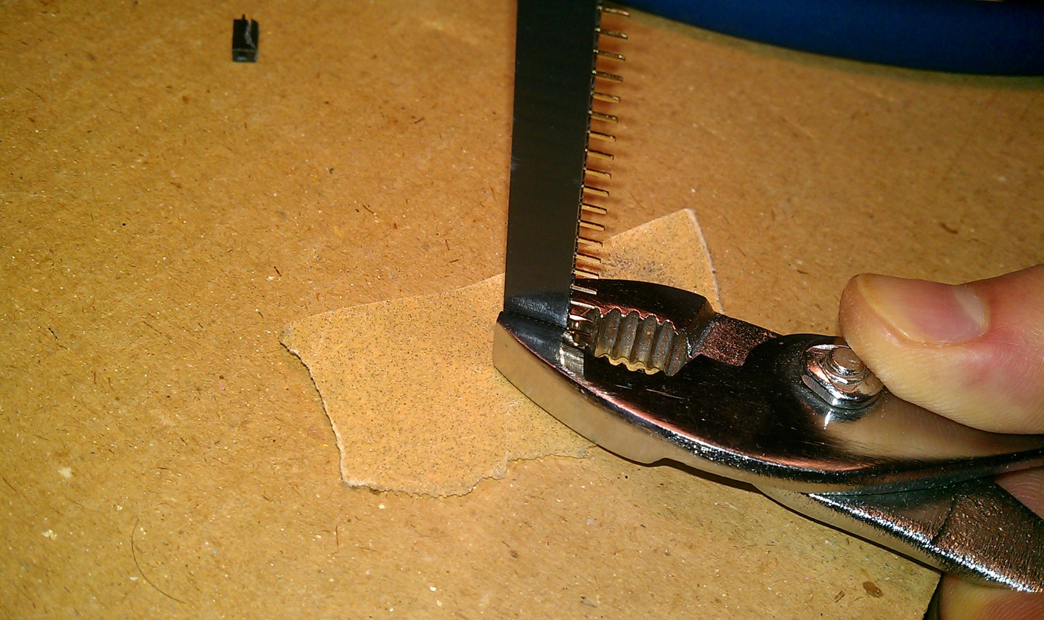
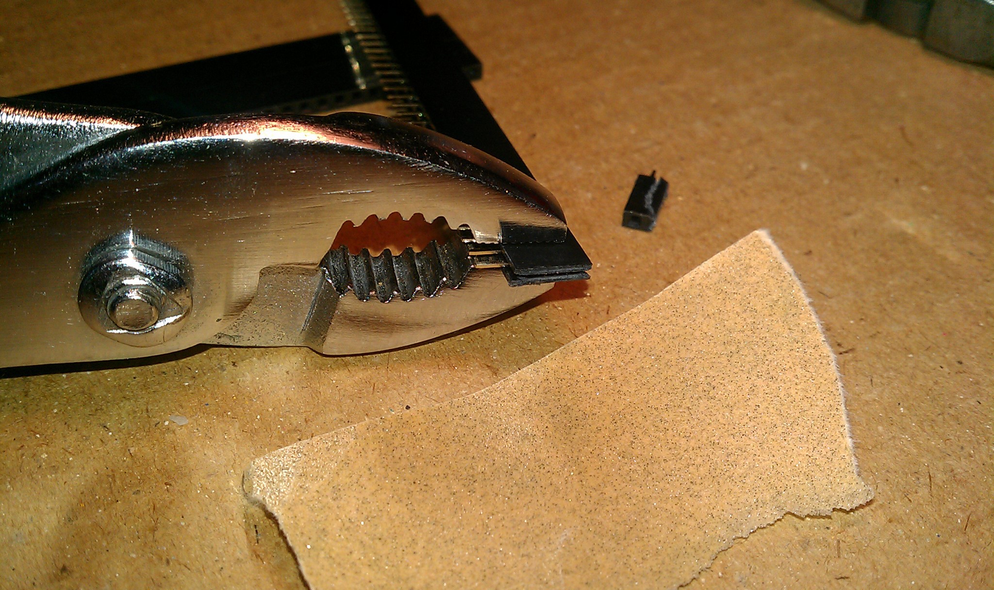
Sand it.
![]()
I had 220 sand paper. I would have preferred higher like 300.
I just eyeballed by hand it every few seconds to get it square.
![]()
The ends won't be seen anyway. They will be glued inside.
![]()
I really wanted to make a thin wooden base for this. Instead I had two thin plastic CD cases that just seemed to fit just right as a temporary base. Three headers on each make two 120 pin sockets (almost) to access the inside.
![]()
Update:
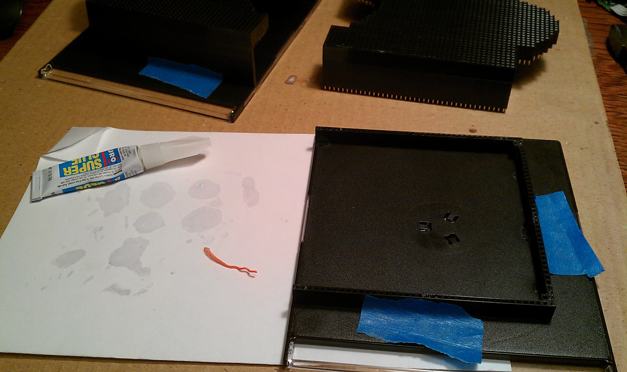
Super glue worked well at first. The cheap stuff gives you a little wiggle time to position correctly. The top split apart a few times at weak spots. Most of the glue joints did well but several were stubborn, even after sanding, as if something spilled on those. I got a Loctite's "Plastics Bonding System Fuses hard-to-bond-plastics" super glue with separate primer/activator. It fixed the stubborn ones, but no wiggle time at all.
-
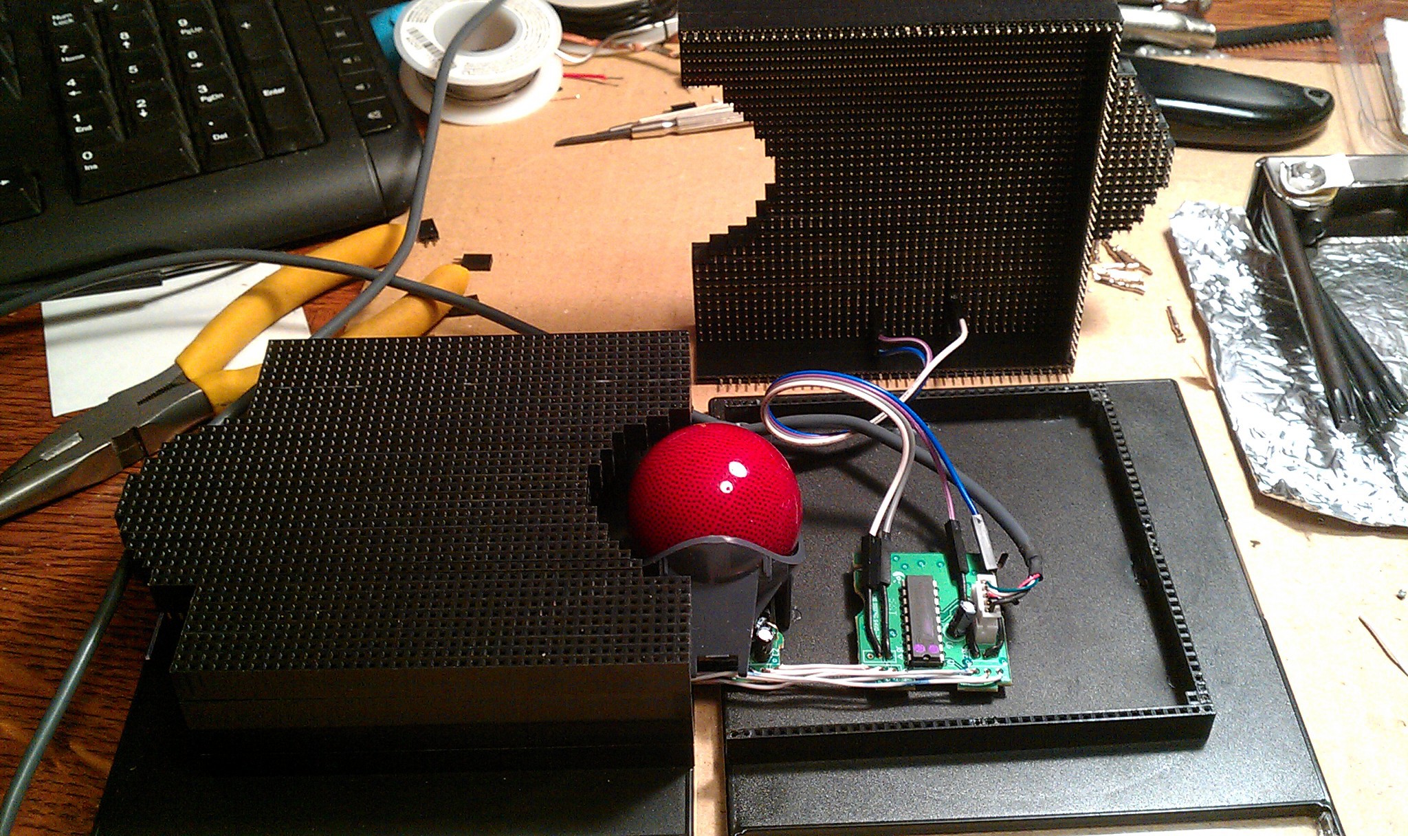
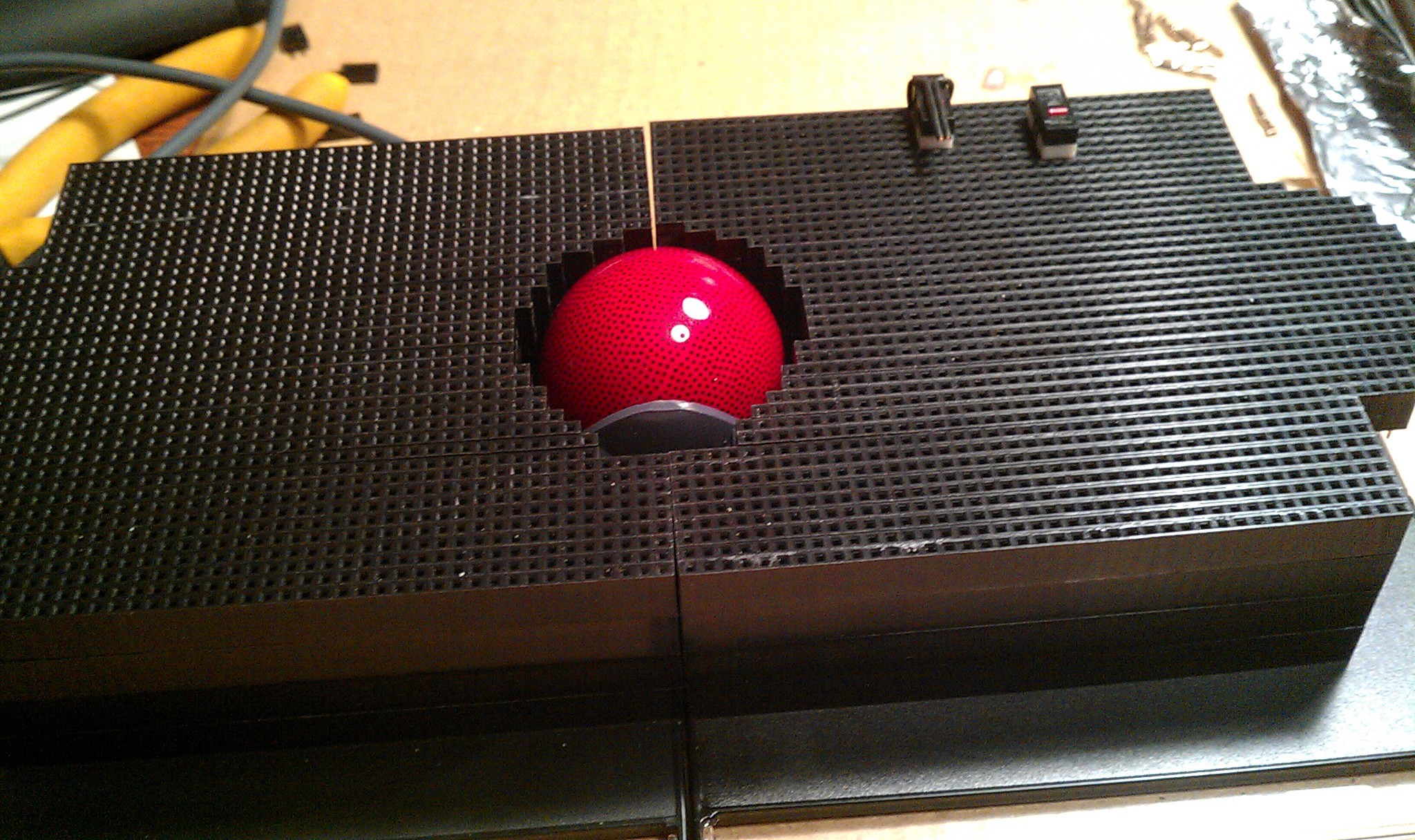
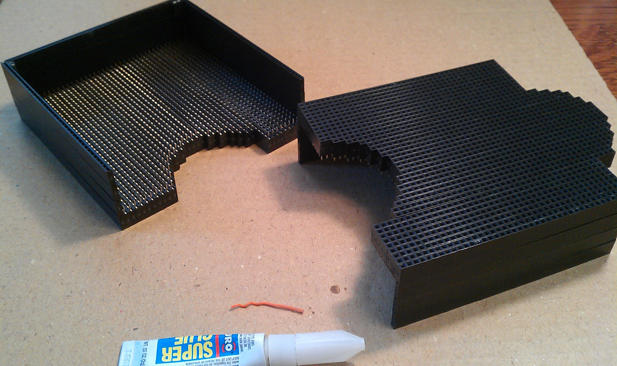
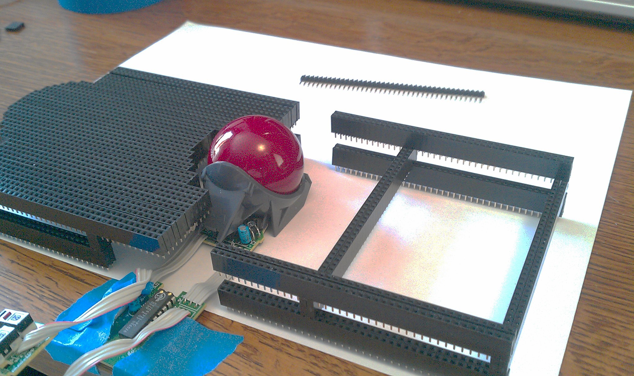
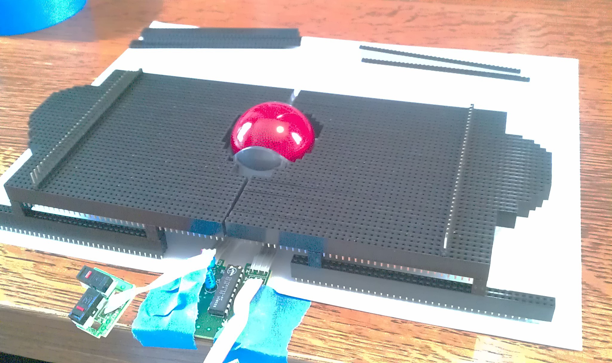
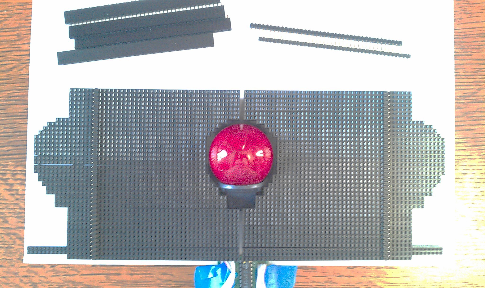
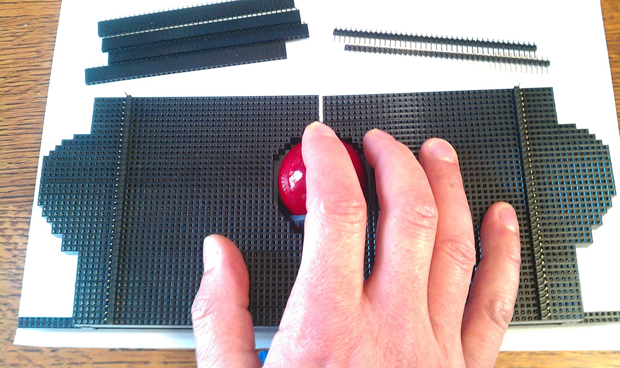
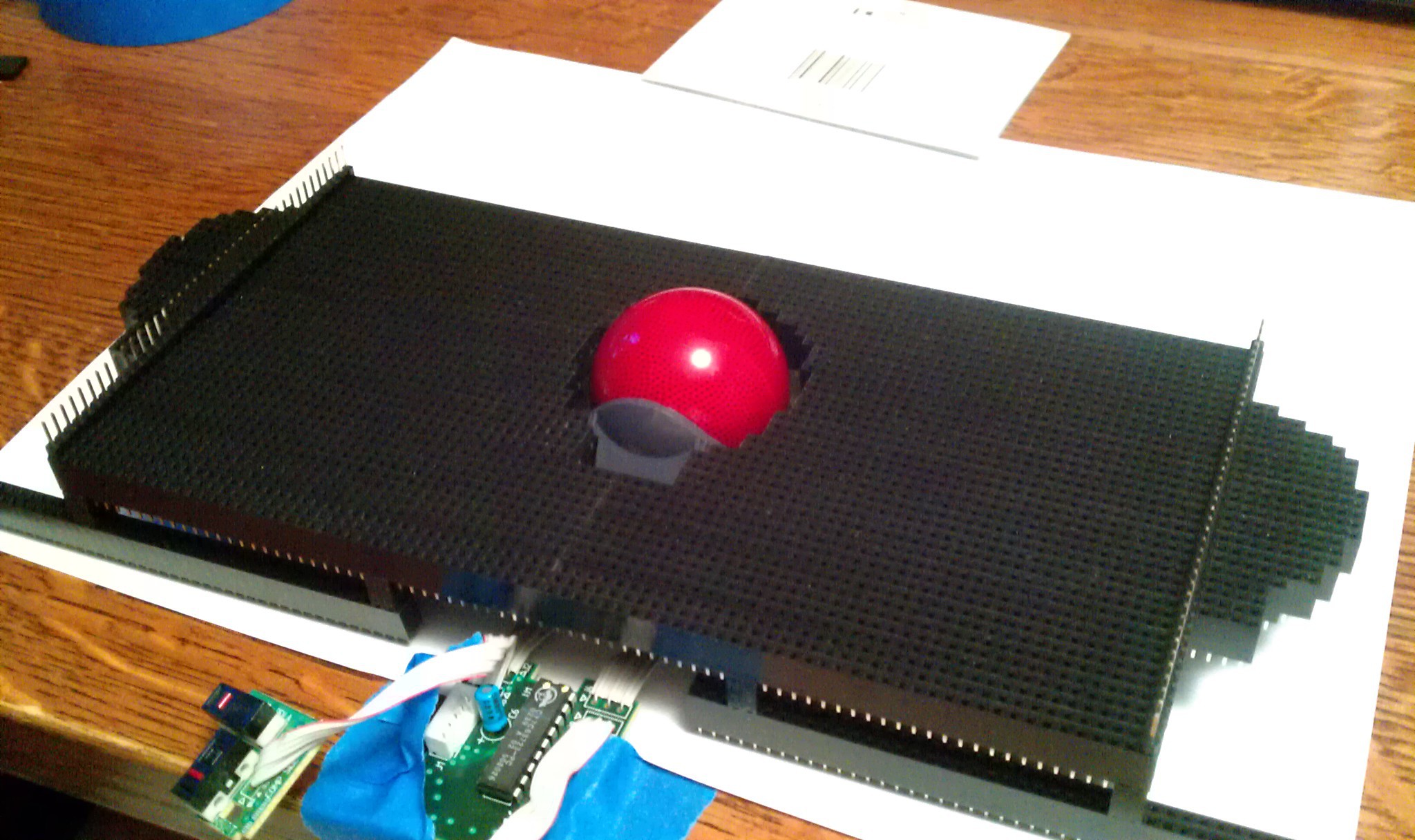
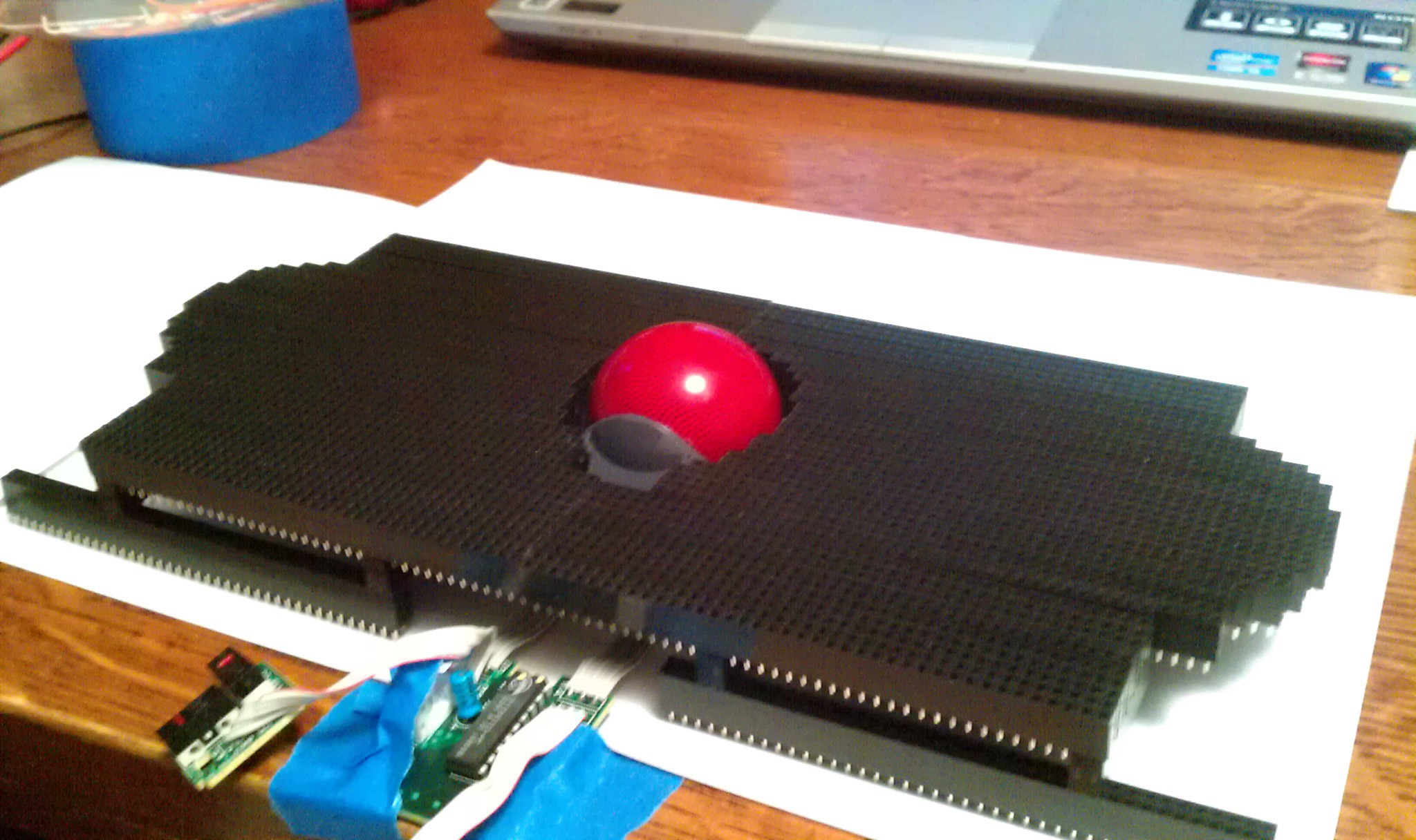
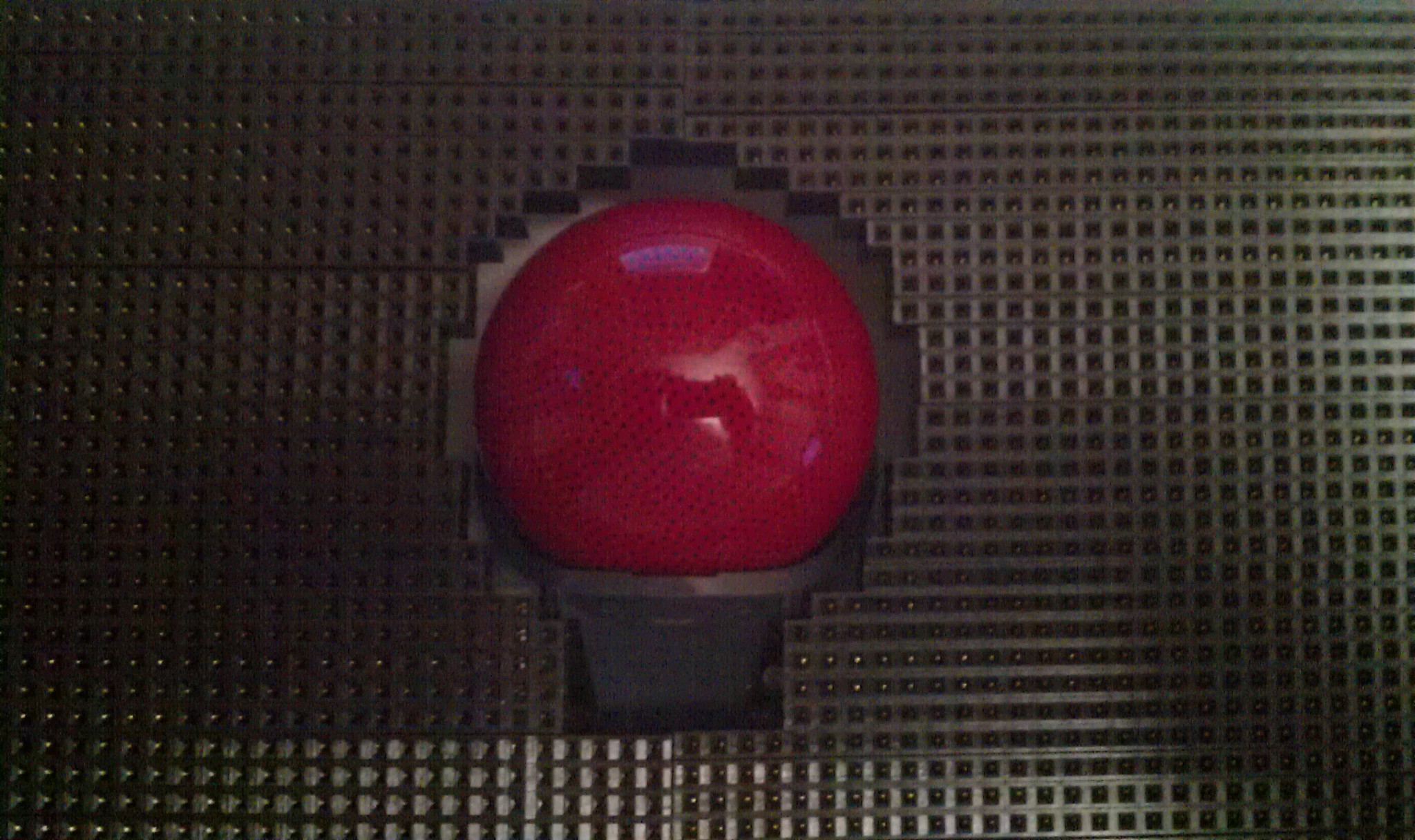
Never Stop Playing With Blocks!
06/10/2014 at 09:34 • 1 commentNever stop playing with blocks; you may lose your imagination, ingenuity, creativity, and grow up and die!
One last dry run to fine tune the shape (its like OCD Legos for nerds!) I did a final adjustment to the shape of the ball and cup assembly. I also moved the ball up more to allow for more lower thumb buttons (hand picture). The final assembly will fill in behind the cup, lower side walls and bottom plate.
![]()
![]()
![]()
![]()
![]()
![]()
![]()
![]()
![]()
Mouse Controller Project
USB trackball mouse controller inspired by Caleb's thecontrollerproject.com.
 I hacked
the USB switch into a hardware solution by having the Teensy
Microcontroller do the switching for me.
I hacked
the USB switch into a hardware solution by having the Teensy
Microcontroller do the switching for me.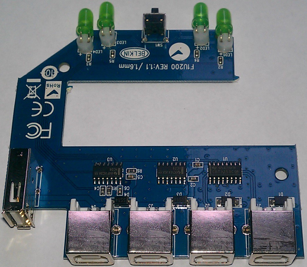 If you cut the board in two, I would want the lower half behind the desk, out of sight with all the wires. The upper half looks like it needs a hacking onto the top of my trackball!
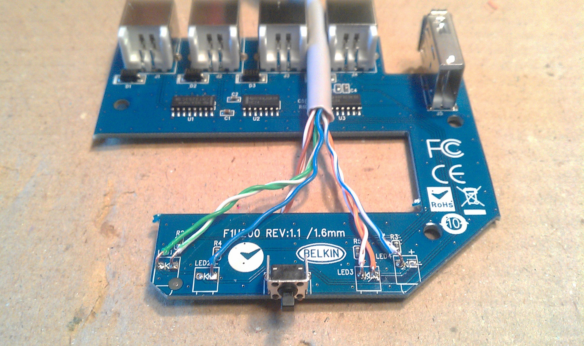 I tested the circuit with a multimeter and the wiring was confusing at first because the left pair of LED's connect anodes to ground, and the right pair connect cathodes to the same ground. To keep it simple, and to utilize the built in resistors...
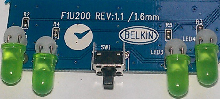 ... I kept the circuit the same through the CAT-5 wires:
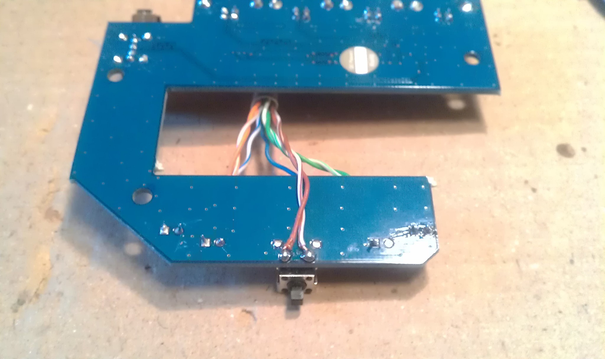 Homemade two pin female jumpers made from two pin headers.
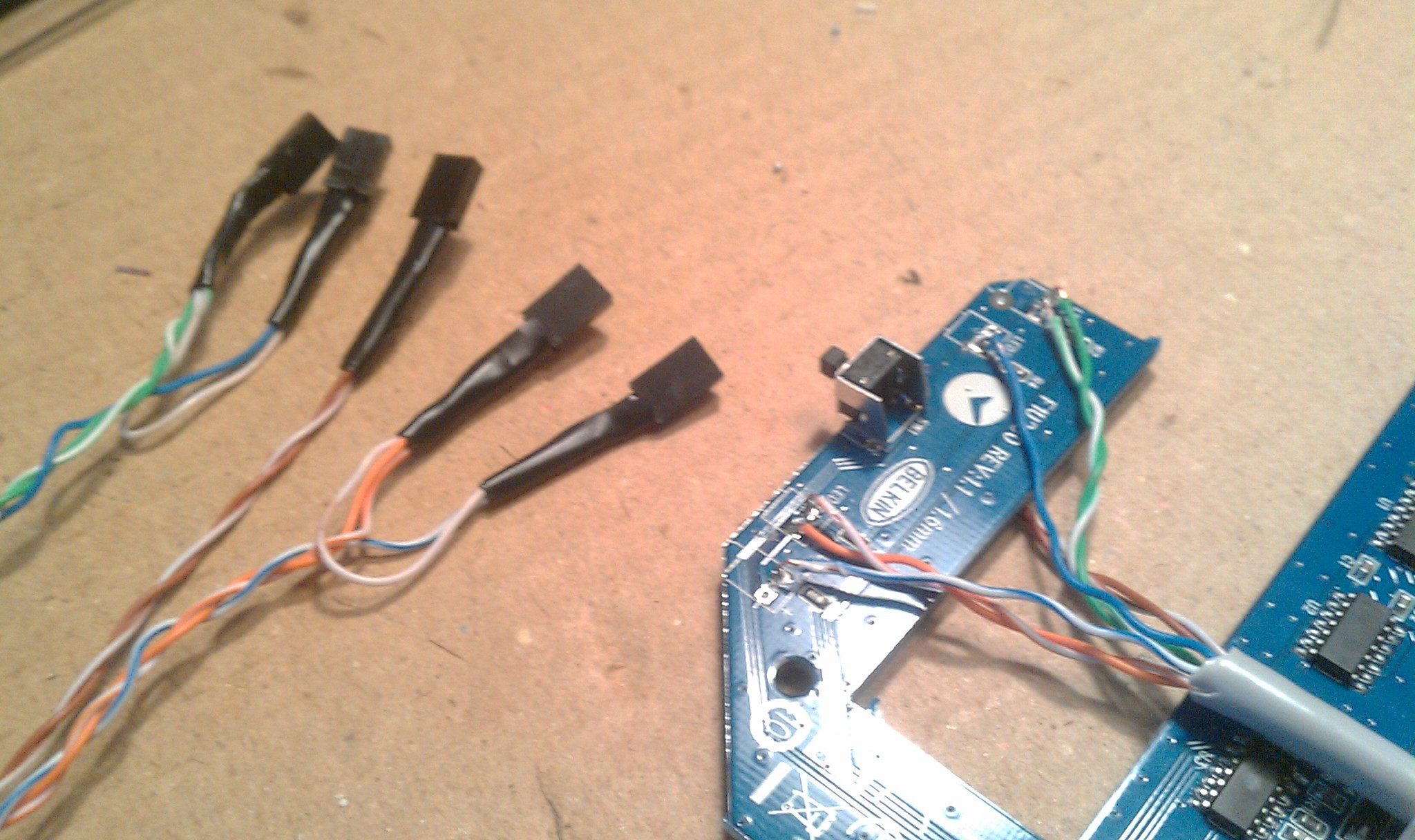 Back in its shell. Cable runs through missing LED hole, strain relieved by a cable tie on the inside.
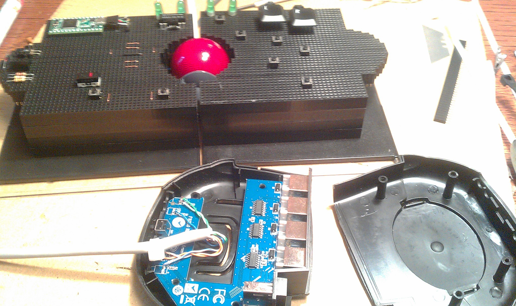
 ... and kept alive to see its own working LED's amputated and transplanted on my track ball.
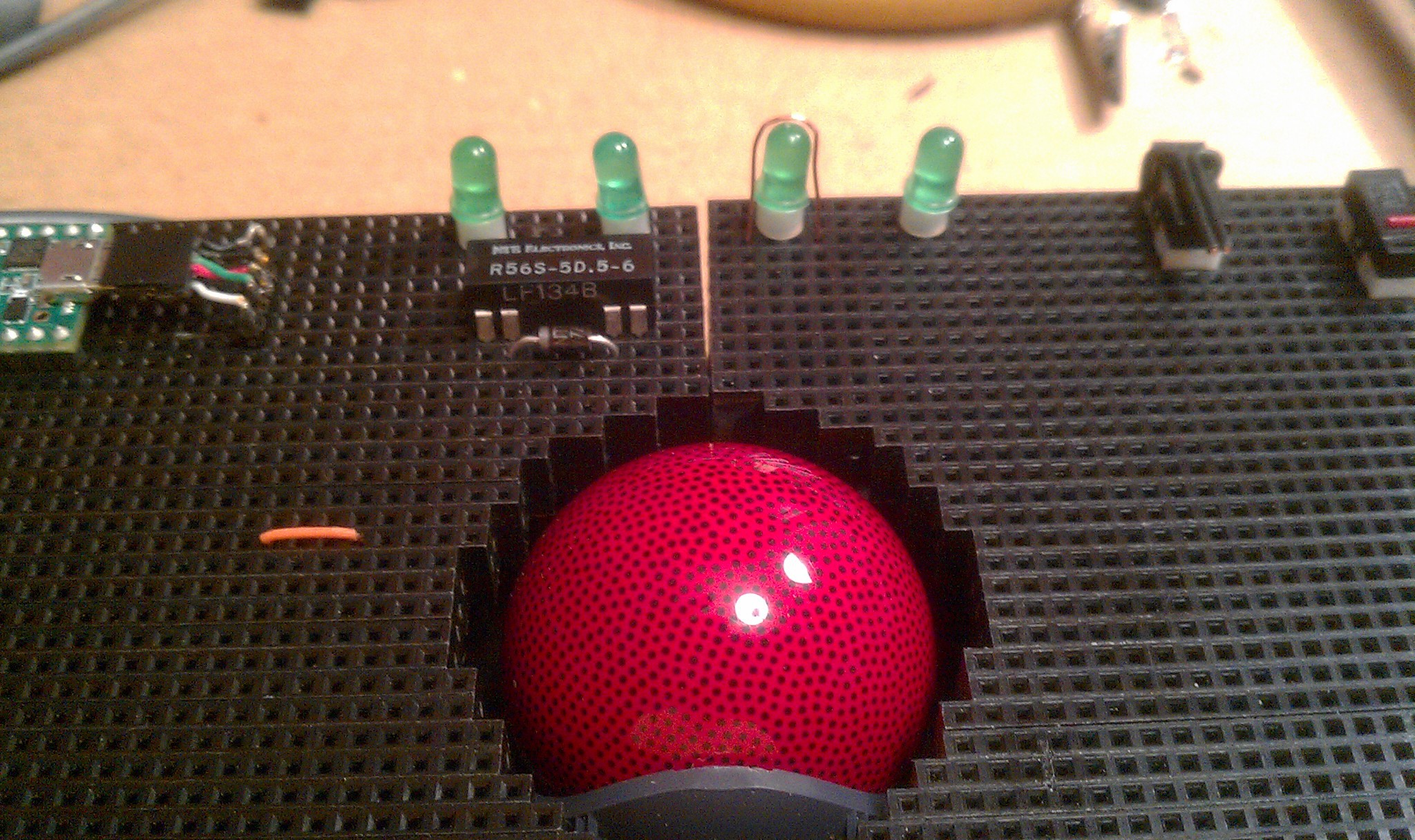 The wire on the third LED is a hacked experiment for touch sensors on LED's.
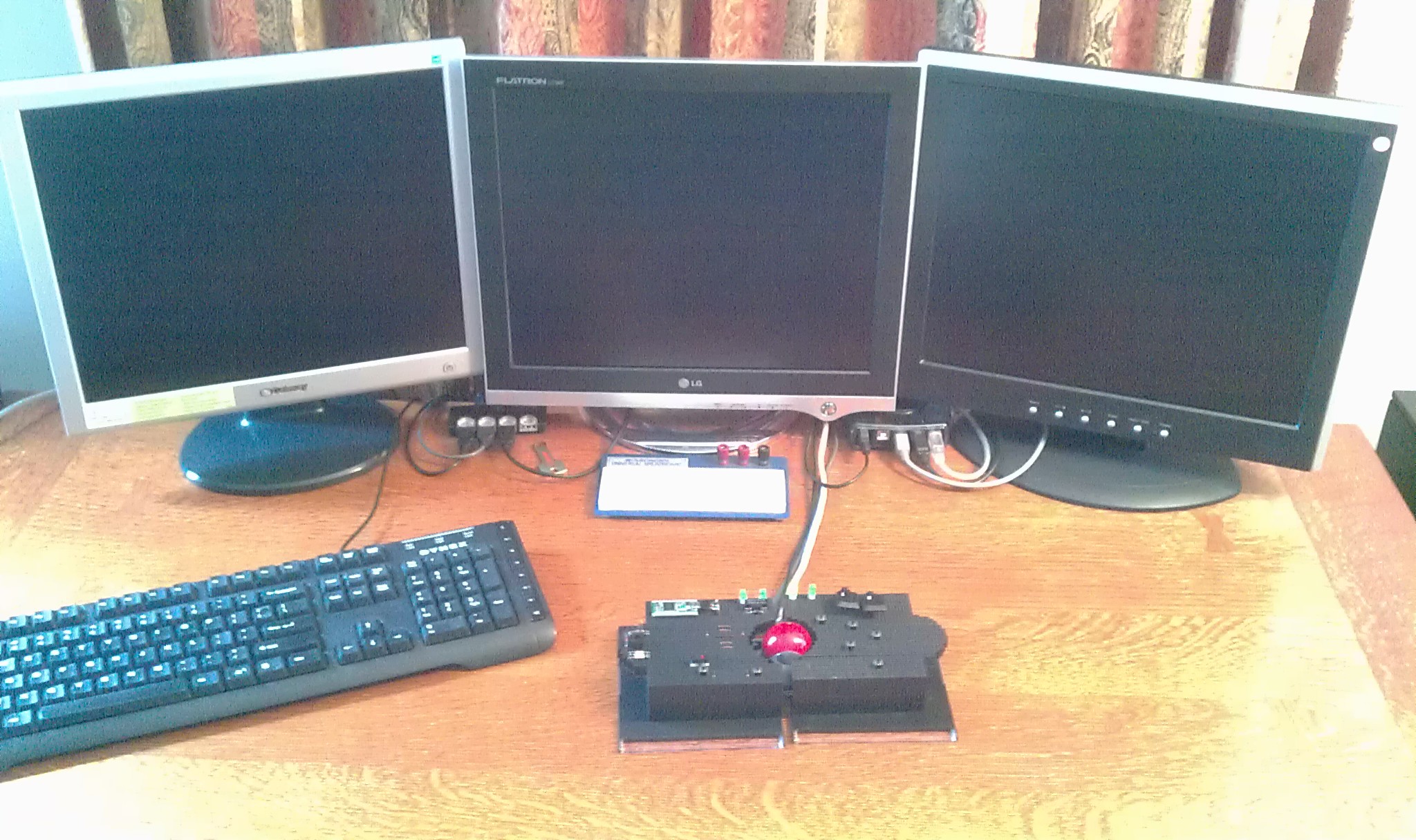
 Then plugged directly underneath the transplanted LED's
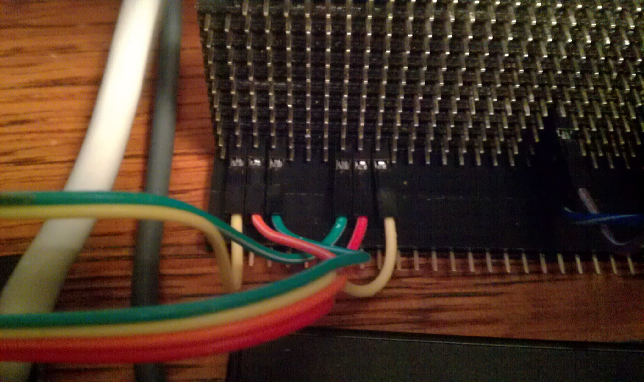 The third jumpers connect under the touch sensor wires.
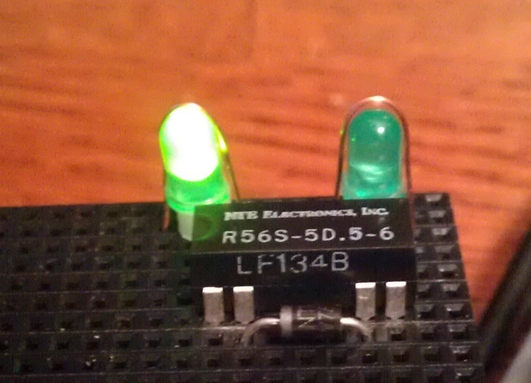 I used an NTE R56S-5D.5-6 reed relay: (5v, 3.8v min), and a "flyback diode." The relay does not have a built in diode. (the "R56S-5D.5-6D does; that first "D" is tricky.
 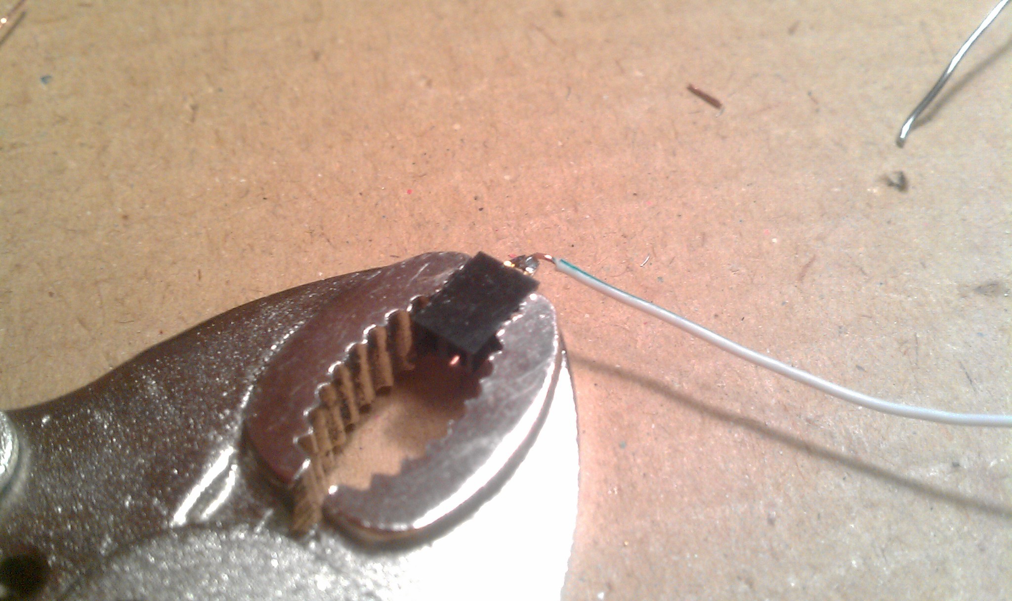 The two header sockets have the wire insert 3mm pin fix. The two male pins are bent together into a two pin jumper, and then soldered to the wire. This connects the relay to the diode in parallel. See relay pins pictured above.
 Two pin jumpers relay to diode:
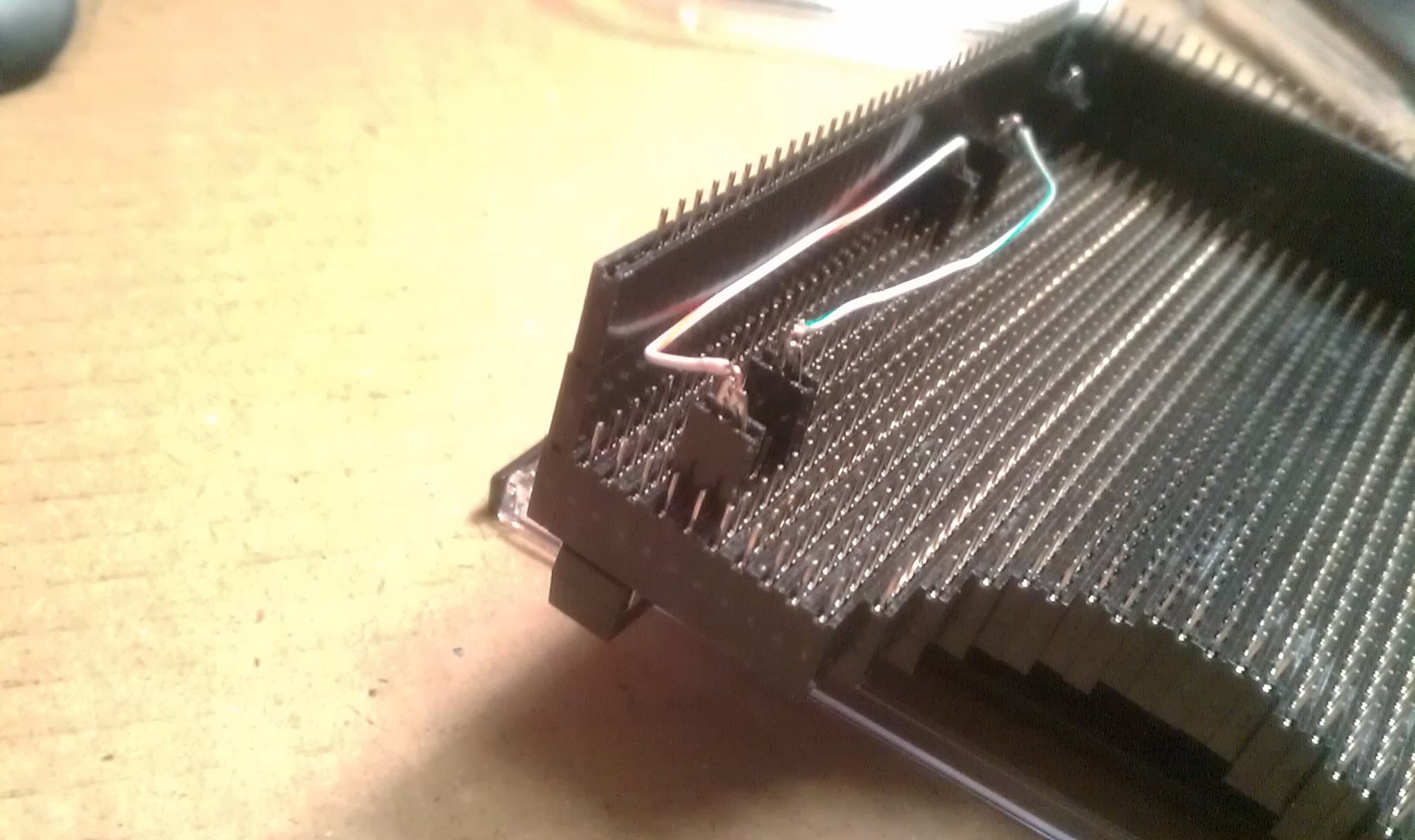
 Its an old style crystal from an old amplifier (I think). I wouldn't think of mixing old tube style components with newer 3.3v logic, but when I saw it, I knew it was going to give my trackball the retro feel it was needing to make it even more artsy. Then later I found out those pin inserts actually made a perfect socket for it.
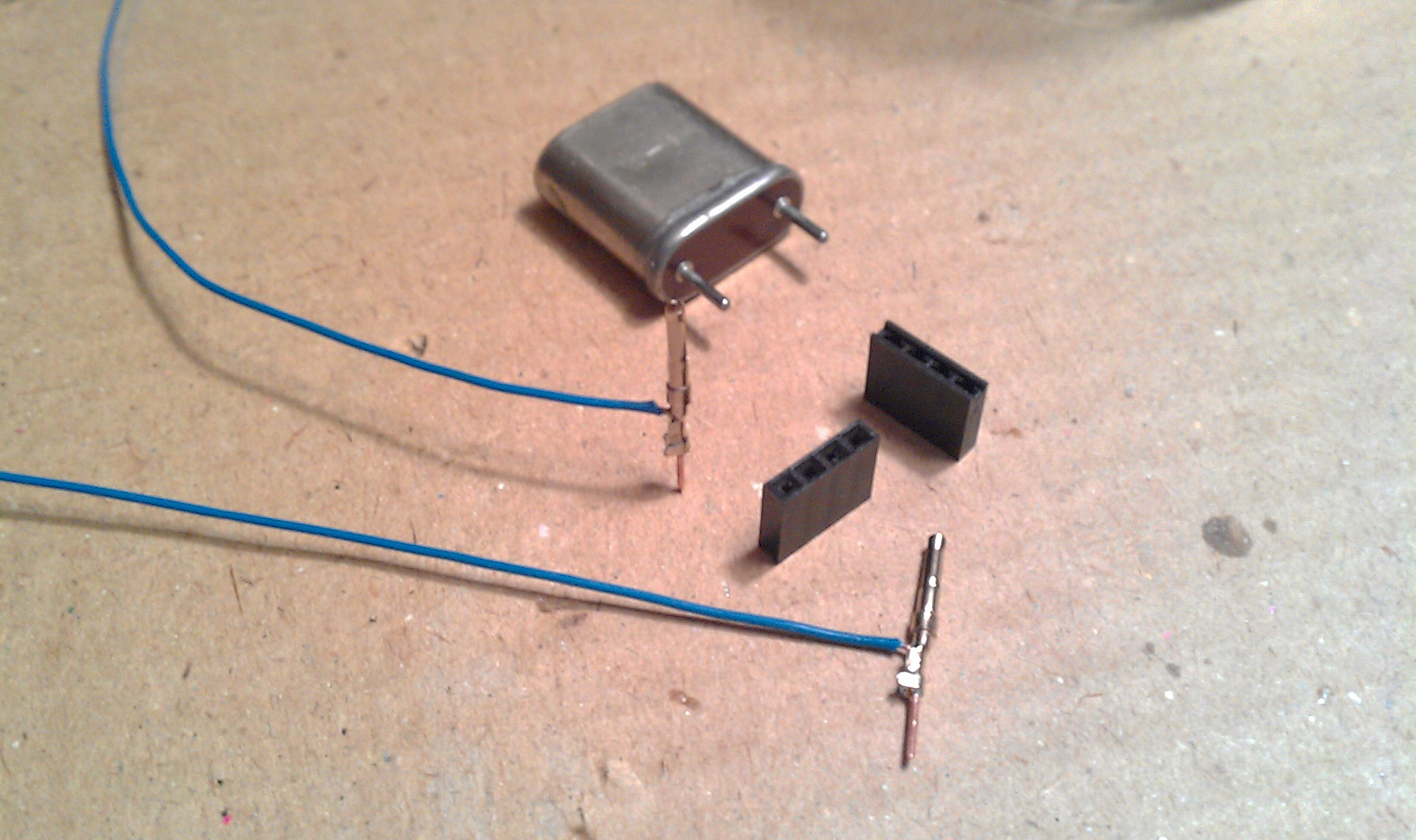 Deadbug Style!
 With headers of course.
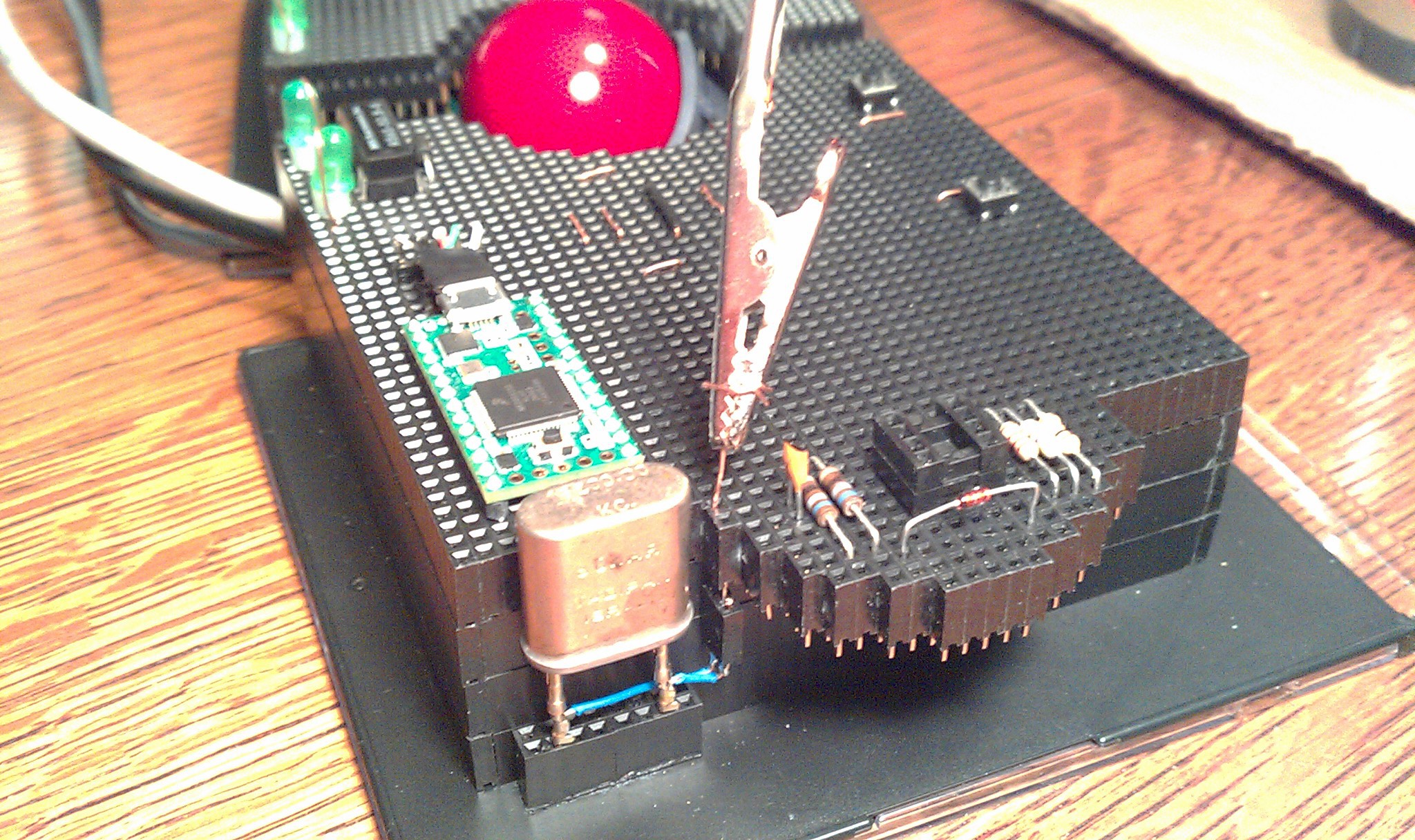 The alligator clip test lead is pointing to the two sockets to the crystal.
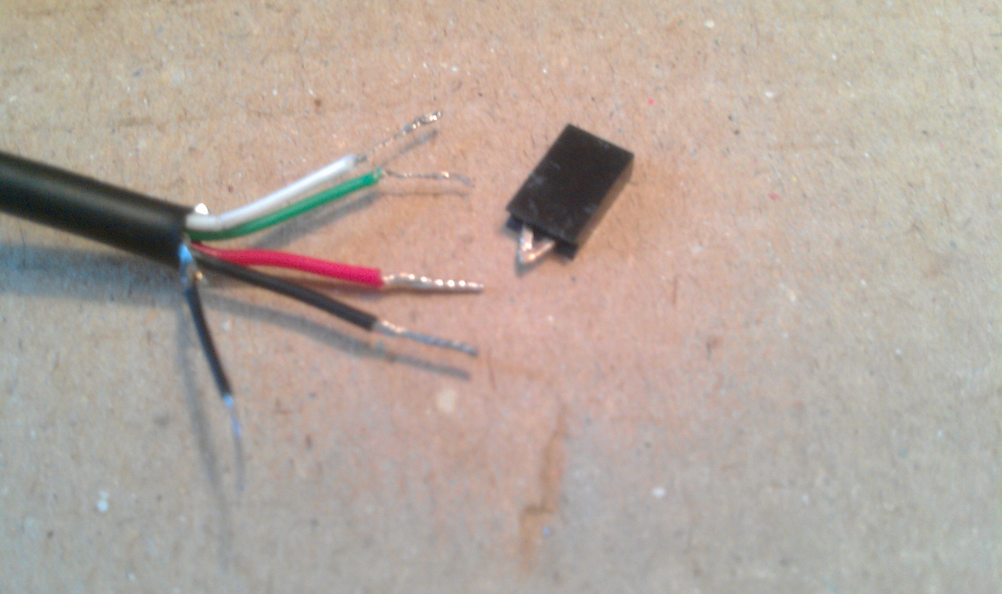
 5x
5x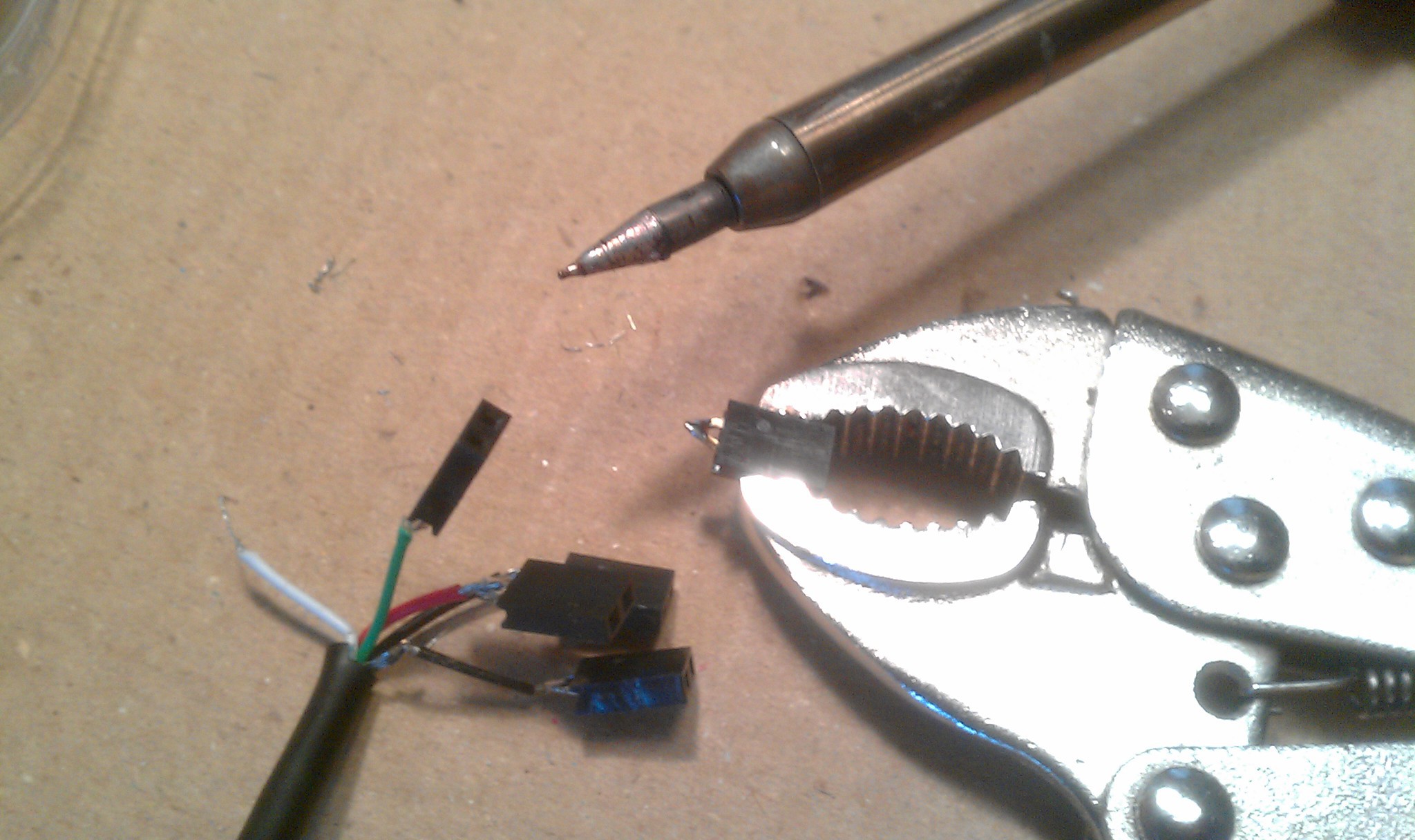 Two pin header sized squares of electric tape between each.
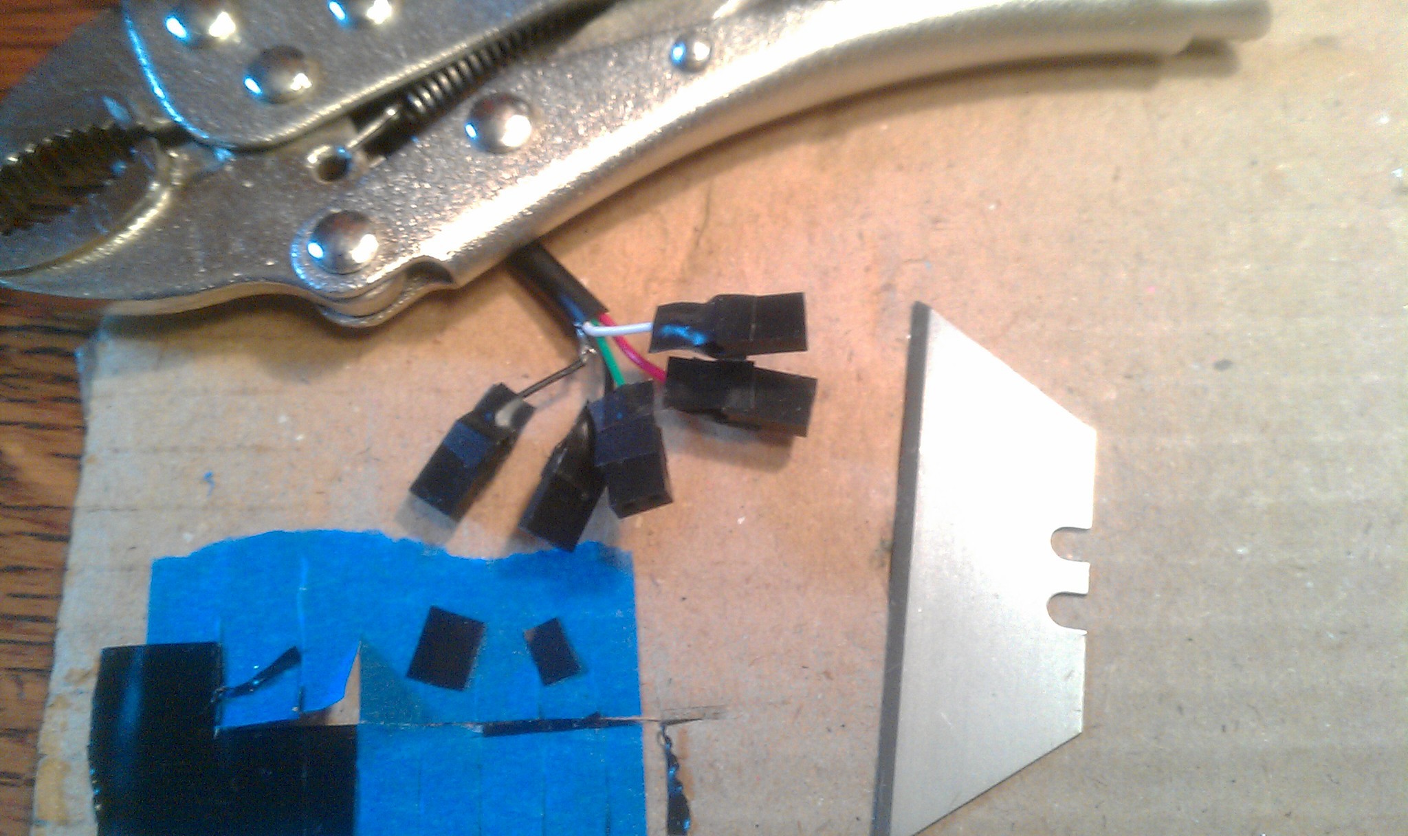 All five super glued together (held in position with two male header strips not shown.)
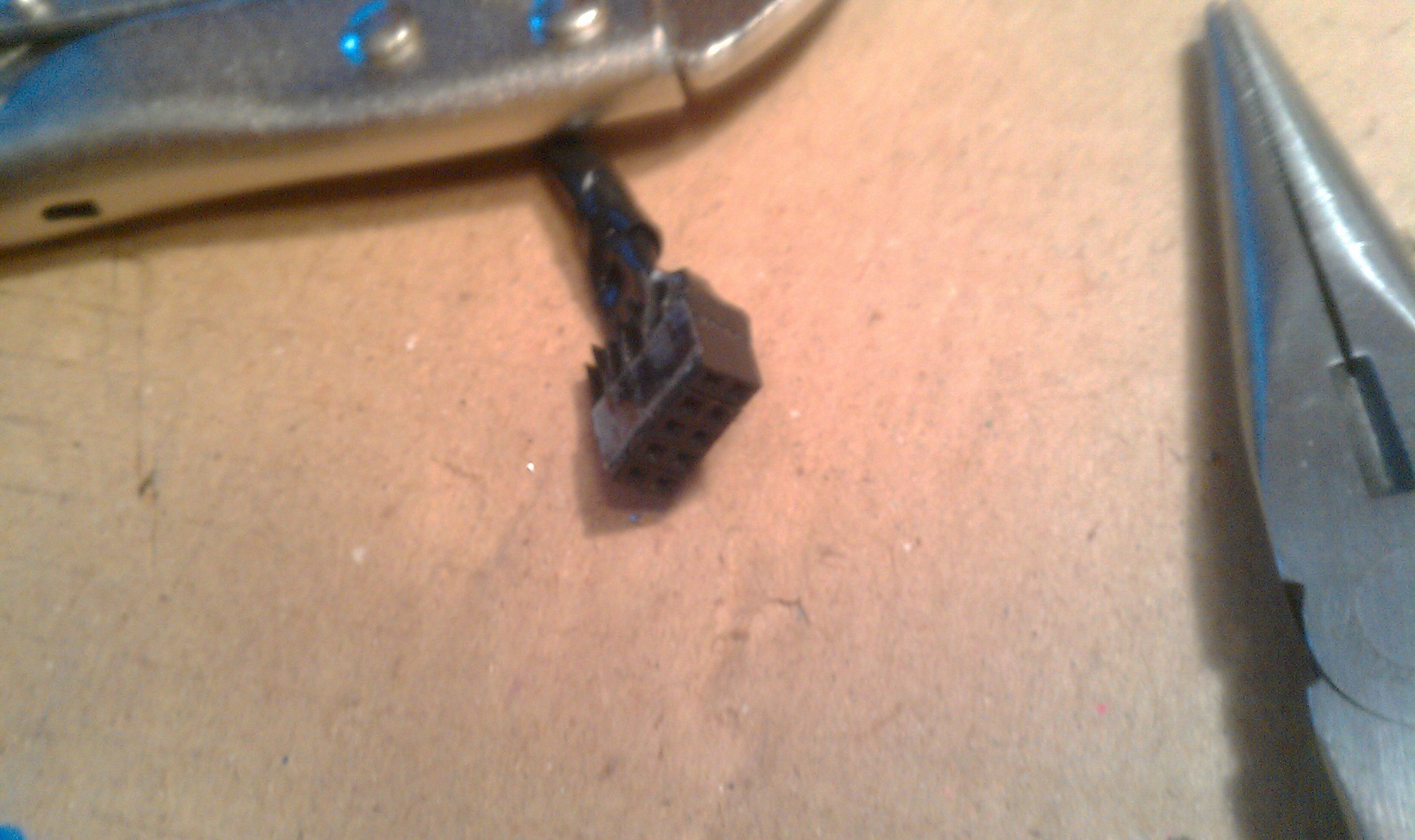 Plugged in underneath.
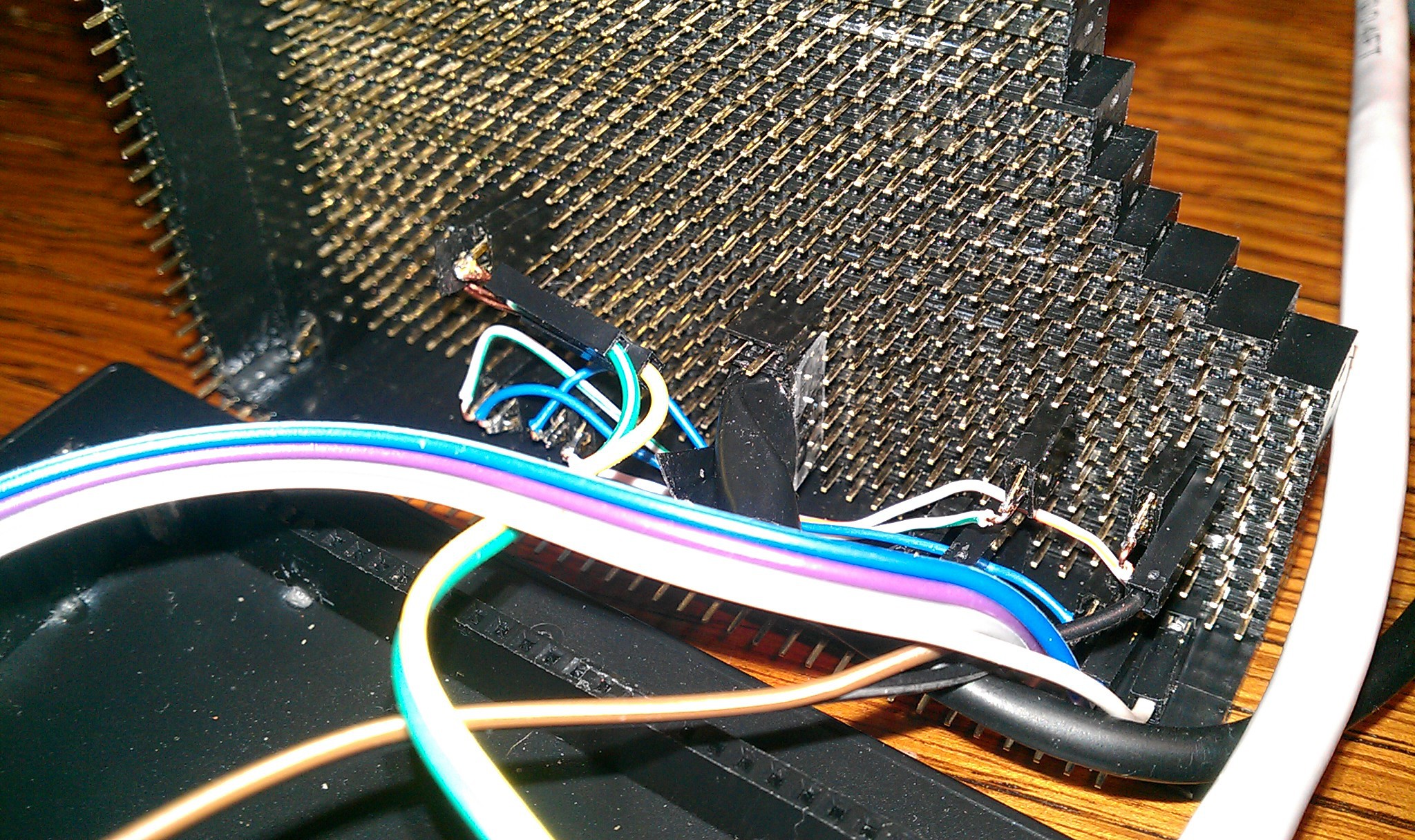 On top I chopped an old USB micro cable for its connector. I had to be careful not to bend the delicate wires barely held on with glue. Soldered to a five pin male header, plugged into place.
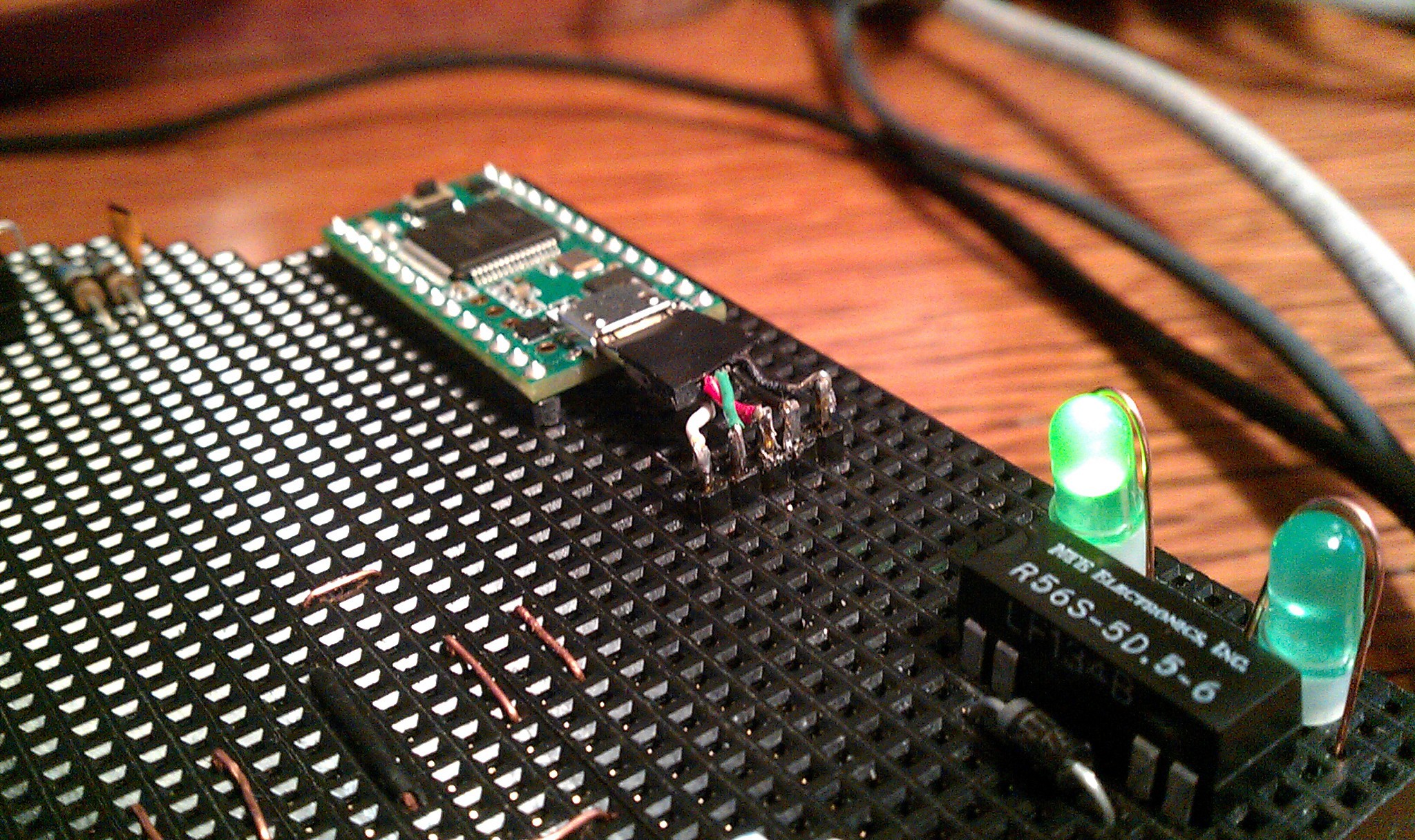 Each pin is duplicated to its corresponding female socket.
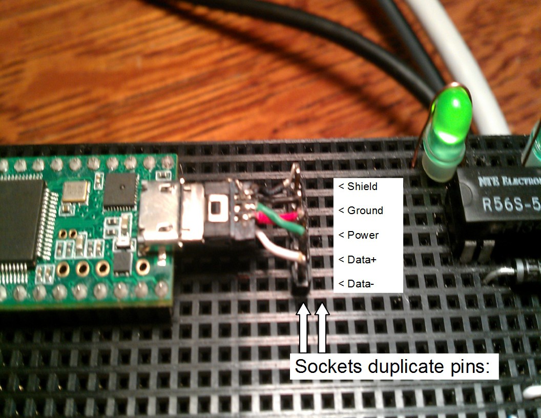
 Then keyboard caps L and R were pried off of an old PS2 keyboard. The wire wrapped around the bottom, making a telegraph style button. Supper light touch and slightly flexible, but defiantly needs something like a 3D printed upgrade.
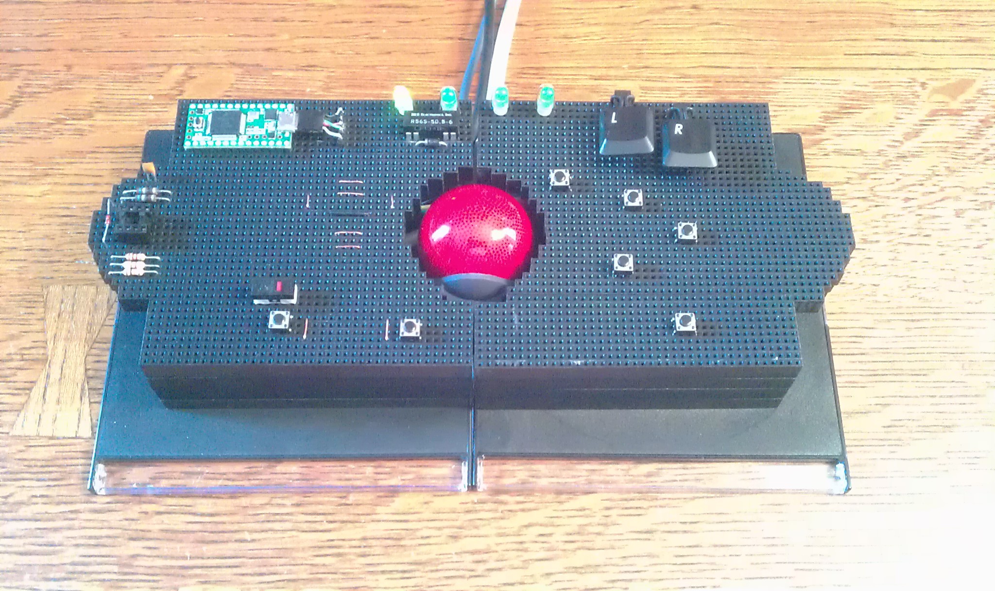
 Chopped
it, soldered it, hacked it.
Chopped
it, soldered it, hacked it.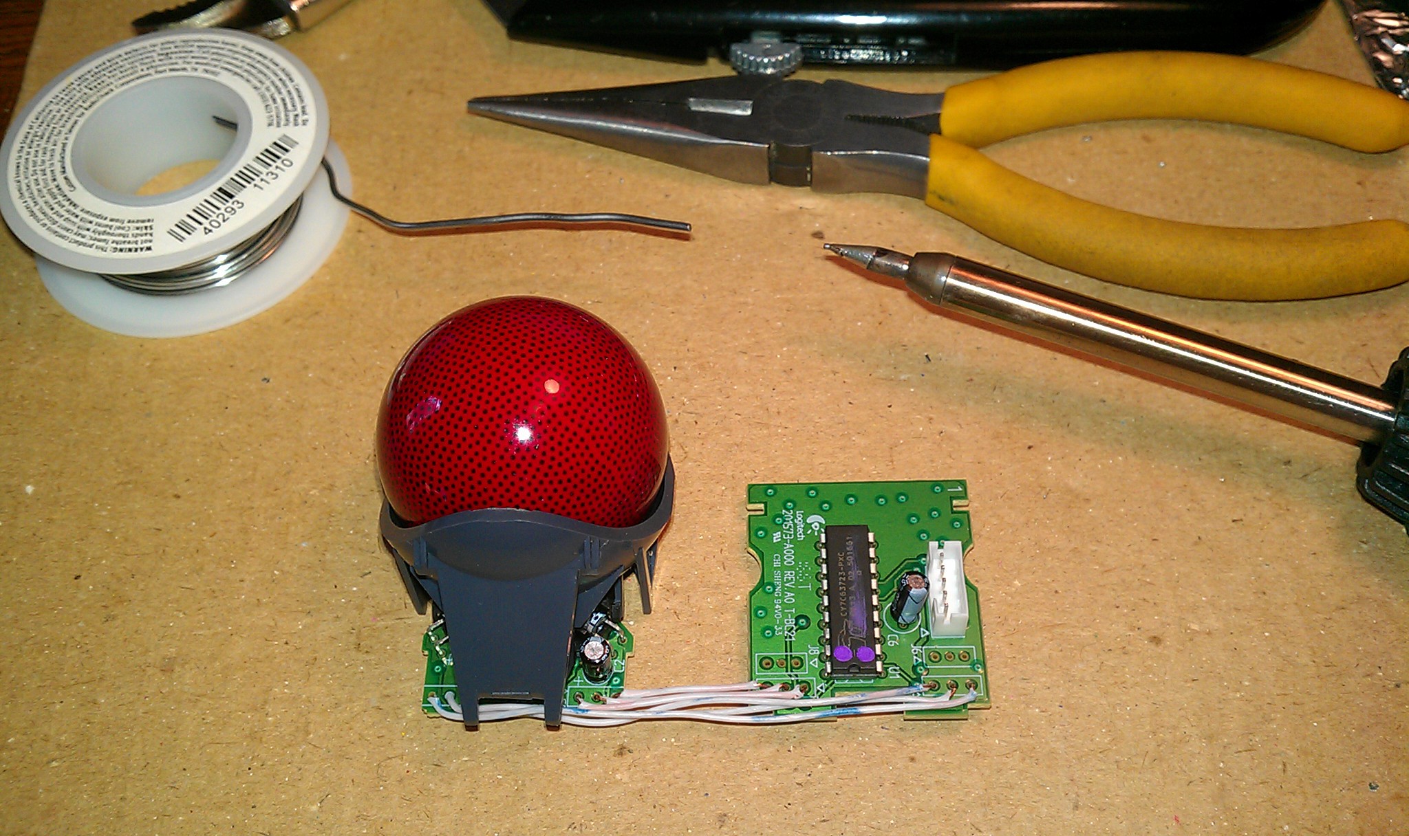 Dead bug
style. I soldered the wires long through the holes to keep air space underneath.
Dead bug
style. I soldered the wires long through the holes to keep air space underneath.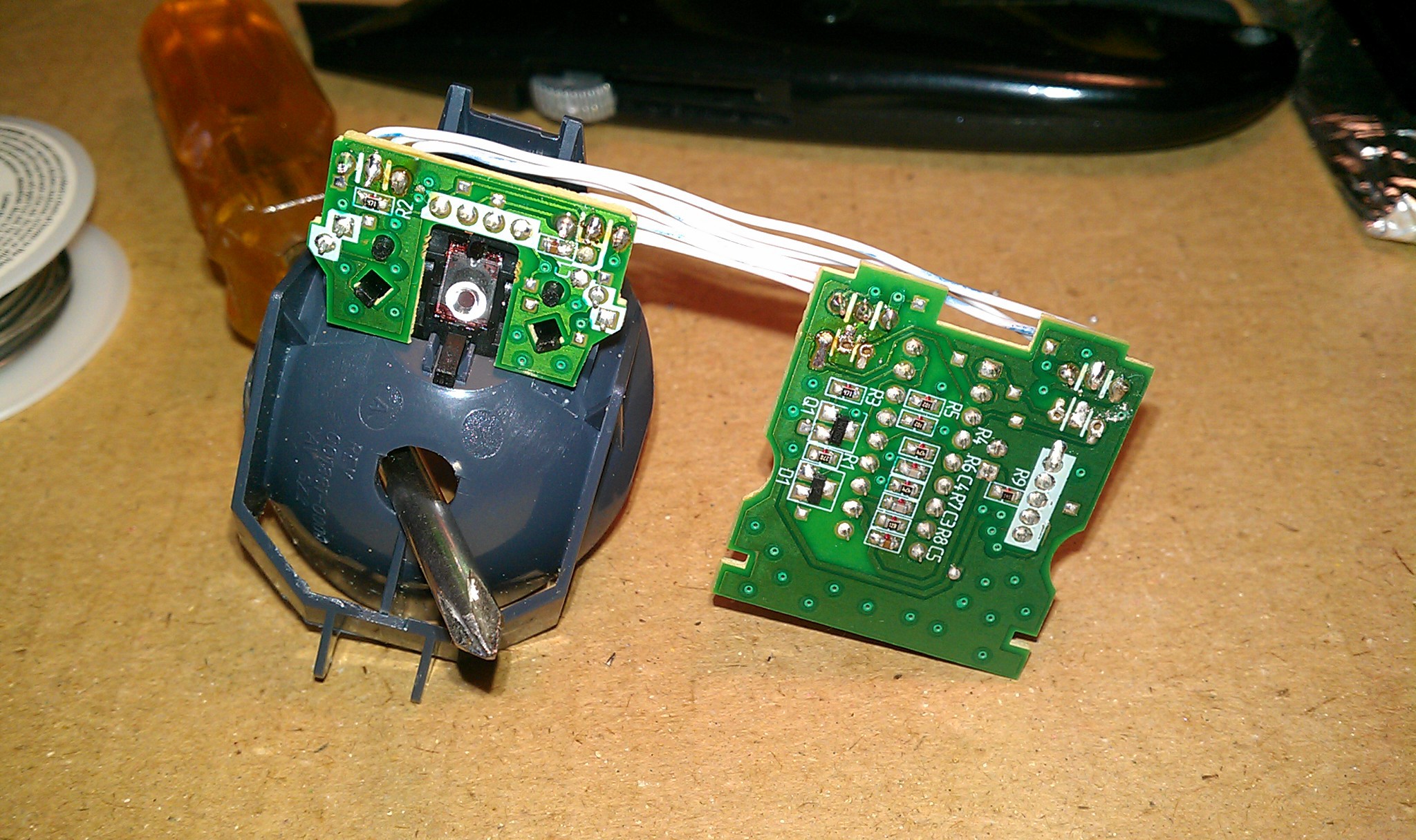 The
black 20 gauge wires soldered on top work with the female jumpers. These are for backup left and right mouse buttons if the Teensy is disabled.
The
black 20 gauge wires soldered on top work with the female jumpers. These are for backup left and right mouse buttons if the Teensy is disabled.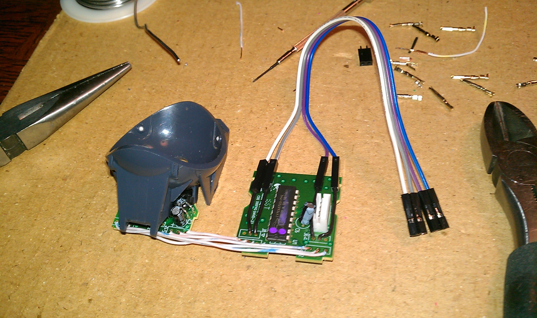
 The first jumpers!