 Alex
Alex-
Redesign on new project site
07/03/2019 at 21:46 • 0 commentsFollow-Up /Redesign here: #192:LED redesign
-
idea for rev2
09/03/2016 at 14:28 • 0 commentsToday I saw a new chip: The IS31FL3733. It is a 192 Led matrix driver. So far it looks like designed for 192:LED. The big improvement over the microcontroller would be: Some real current limiting, which would end up in more consistent brightness; not programming needed (i2c interface to main/host controller); simpler circuit maybe. And you could control more than one 192:LED-module over the same i2c Bus.
I am thinking of changing the PCB design to fit with this driver IC.
-
load images over uart on the display - the simple way
07/02/2016 at 16:19 • 0 commentsIn the last log I wrote about a quite complicated way to load images to the display. I now have improved the octave script. it no loads the image itself to the display:
This is done by using the instrument-control package of octave:
function IMG_test

  pkg load instrument-control
  if (exist("serial") != 3)
    disp("No Serial Support");
  endif

  myImage = imread("image.png");  #read 8x8 pixel image
  # the image is vreatet with MS paint. At least there each
  # pixel is encoded into three bytes (R,G,B) this could be
  # normal for png. At least I hope so

  # now to the conversation magic
  red   = uint8(bitshift(myImage(:,:,1), -5));
  green = uint8(bitshift(myImage(:,:,2), -5));
  blue  = uint8(bitshift(myImage(:,:,3), -5));

  #add the three colors to one byte togehter
  img8trueColor= bitshift(red,5) + bitshift(green,2) + blue;
  #transpose the image - needed to save it correctly
  img8trueColor=img8trueColor.';

  #write it to display direct in octave no more a file output
  s1 = serial("\\\\.\\COM12");
  set(s1, 'baudrate', 38400);
  srl_flush(s1);
  srl_write(s1, img8trueColor);

endfunction
The source code is also in the github repository.helpful links for octave and uart:
http://wiki.octave.org/Instrument_control_package
http://www.edn.com/design/analog/4440674/Read-serial-data-directly-into-Octave
http://projectsfromtech.blogspot.de/2015/03/serial-port-communication-with-gnu.html
-
load images over uart on the display
06/28/2016 at 20:38 • 0 commentsWARNING: This will get some more and complicated...
I did broke out the RX pin on the PCB to get the possibility to sent images over UART to the display. And this is now also working. I also want to offload most of the processing to the UART sender (now just a PC with USB-UART bridge, but later perhaps some master Microcontroller/FPGA) . So I decided to just send the image as it is also coded internally:
- 8 Byte per pixel
- In the byte all three colors like RRRGGGBB (sometimes this is called 8 bit true color, it is not my idea)
- so I need 64 Byte per image
- The Byte order is chosen by me the first byte is the top right pixel an than follow the first line and so on
The UART part was made fast and easy, but getting the needed data was complicated. I found no graphic program which saves images in 8 bit true color. So I decided to script some matlab/octave to that:
function IMG_test

  myImage = imread("image.png");  #read 8x8 pixel image
  # the image is vreatet with MS paint. At least there each
  # pixel is encoded into three bytes (R,G,B) this could be
  # normal for png. At least I hope so

  # now to the conversation magic
  red   = uint8(bitshift(myImage(:,:,1), -5));
  green = uint8(bitshift(myImage(:,:,2), -5));
  blue  = uint8(bitshift(myImage(:,:,3), -5));

  #add the three colors to one byte togehter
  img8trueColor= bitshift(red,5) + bitshift(green,2) + blue;
  #show the reult (just for visual inspection)
  imshow(img8trueColor);
  #transpose the image - needed to save it correctly
  img8trueColor=img8trueColor.';
  myFile=fopen("out.txt", "w");
  fwrite(myFile,img8trueColor);
  fclose(myFile);
  #{
    The out put file now should look like this:
    07 E0 00 1A 1A 1A E0 1C
    07 E0 00 1A 00 1A E0 1C
    07 00 00 1A 1A 1A 00 1C
    07 00 00 1A 00 1A 00 1C
    07 00 23 00 F2 F2 00 1C
    07 00 23 00 00 F2 00 1C
    07 00 23 00 00 F2 00 1C
    07 E0 23 23 00 F2 E0 1C
    The first eigt bytes (first line) are the top line of the
    display also.
  #}
endfunction
This small script is some kin of user unfriendly, but working. My workflow now is:- create some 8x8 pixel image (I used just MS paint)
- save it as png
- store it in the directory of the octave script
- run the octave script
- now you have a 64Byte big file named "out.txt"
- sent "out.txt" with Realterm over the UART to the display ( the file is *.txt because this is the only supported filetype by Realterm)
So now some result and images:
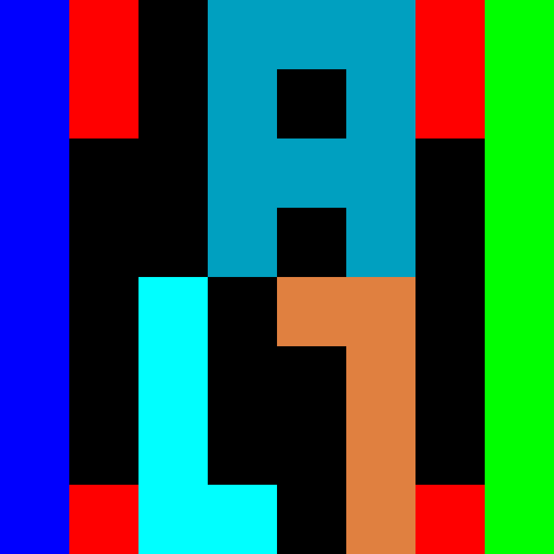
This is my in step 1 created image:
![]()
My octave script create me now this file:
07 E0 00 1A 1A 1A E0 1C
07 E0 00 1A 00 1A E0 1C
07 00 00 1A 1A 1A 00 1C
07 00 00 1A 00 1A 00 1C
07 00 23 00 F2 F2 00 1C
07 00 23 00 00 F2 00 1C
07 00 23 00 00 F2 00 1C
07 E0 23 23 00 F2 E0 1C
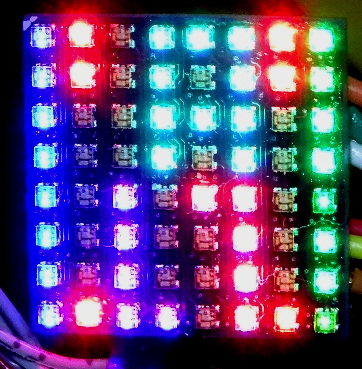
00 is black; 07 is blue; 1C is green and so on.....After sending this to the display the display looks like this:
![]()
The colors are at least similar as in the original image. Maybe I will add some kind of color correction to the octave script.
So with a fas enough master device, which has lots of (or multiplexed) UART outputs and some more image (or video) software on it, I could now build big displays with this.
-
rainbow animation now also on 192:LED
06/26/2016 at 20:25 • 0 commentsIf you follow my other led display project ( #384:LED) you could already know this animation. I is know also running on this display:
-
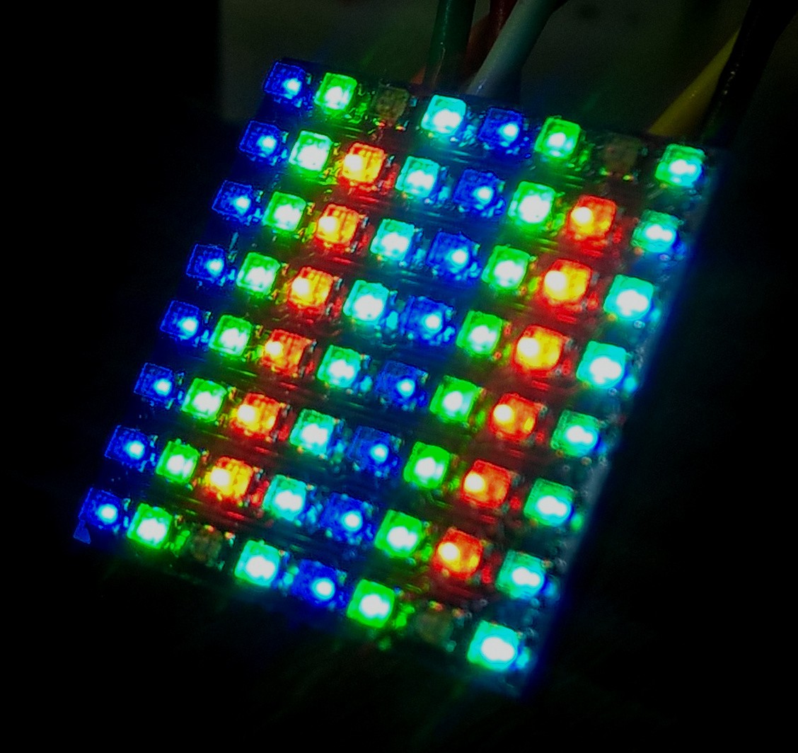
192:LED is alive
05/28/2016 at 19:58 • 0 commentsAfter some rework it is now working. There was also something wrong with the 0201 Capacitors. They are the load capacitors for the crystal. Maybe just the value was wrong. But it also works without them, so I did no further investigation yet.
![]()
The missing red LEDs on the picture are because the one red column is not connected. This is because the IO pin is shared with MOSI. To activate them I have to bridge a jumper and this is not done.
Next will be to add some annimations or adding a controll interface.
-
(extreme) soldering Part Two
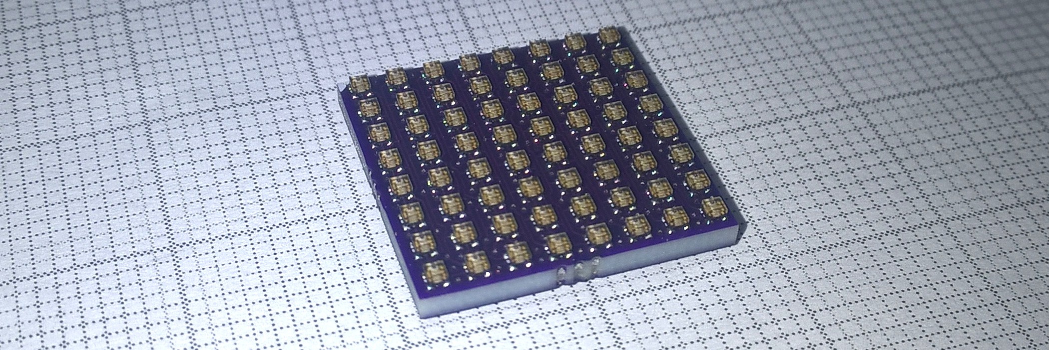
05/28/2016 at 11:56 • 1 commentJust a quick update. The top side with it's 64 RGB LEDs is also soldered:
![]()
The Grid in the background is 1mm. I hope it will work. But to test that I have to write some firmware first. I made A video while placing and soldering, maybe I will made a Timelapse video of that.
-
(extreme) soldering Part One
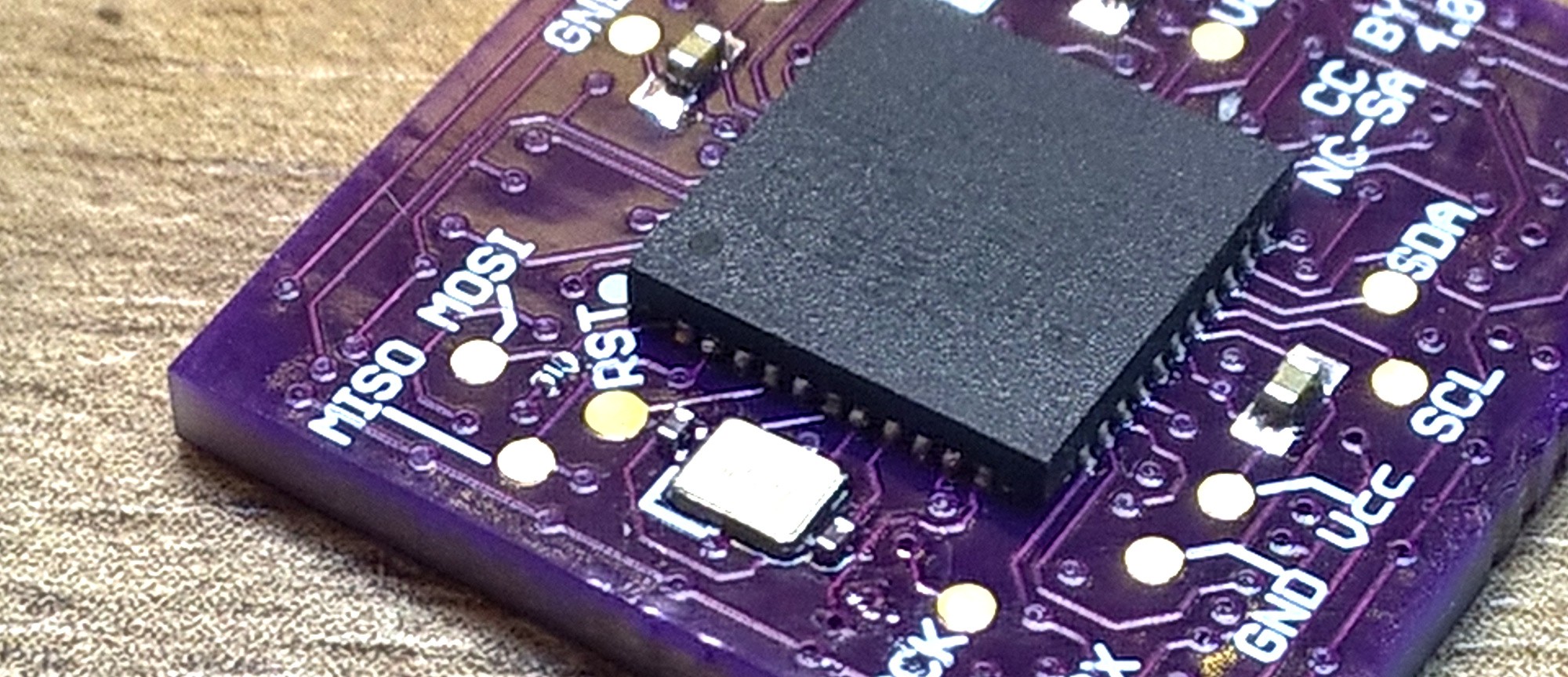
05/25/2016 at 19:25 • 7 commentsThe bottom side is soldered. It was quite difficult to get the 0201 capacitors (the two next to the crystal) soldered correctly. The dimension of crystal is 2 x 1.6 mm.
![]()
Next Task is to solder the to side with its 64 RGB Leds. But I will not do that today. One side a day extreme soldering is enough. And then I hope it will also work.
-
Getting Parts - Recycle a Microcontroller
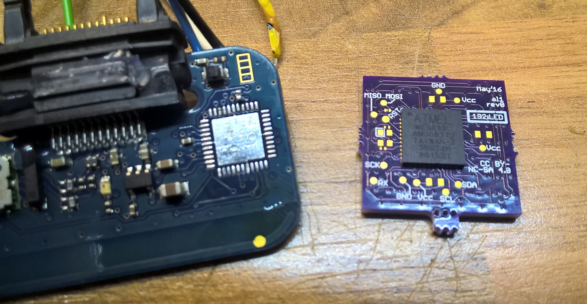
05/19/2016 at 17:33 • 1 commentWhat is the cheapest way to get Microcontrollers? Well desolder them from other boards is often quite cheap. A suitable Controller is also on the MMMR-70 radio Modules. I bought ten of them some time ago (see #Yet another MMR-70 project). And for 0.7€ you can not get a new ATmega32.
![]() You should only take care about the fuse settings of the controller. I did reprogrammed them to default before desolder the ATmega from the MMR-70 board.
You should only take care about the fuse settings of the controller. I did reprogrammed them to default before desolder the ATmega from the MMR-70 board. -
Boards and stencils are in
05/18/2016 at 16:28 • 0 commentsBoth was in the mail today:
![]()
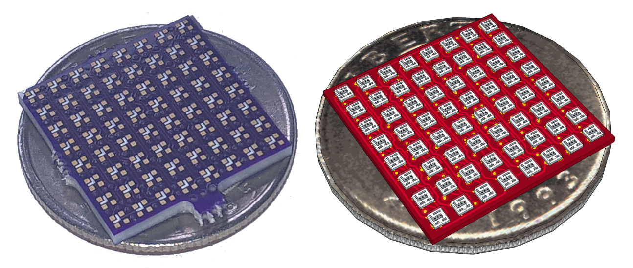
The board does look really similar (beside of the color) to the rendering a made before:
![]() On the left is a photo the right is the rendering. Luckily I found a real ¼US$ coin at home.
On the left is a photo the right is the rendering. Luckily I found a real ¼US$ coin at home.
192:LED
Extreme tiny (0,68'‘ x 0,68’‘ or 17mm x 17mm) smart RGB LED display/matrix
 You should only take care about the fuse settings of the controller. I did reprogrammed them to default before desolder the ATmega from the MMR-70 board.
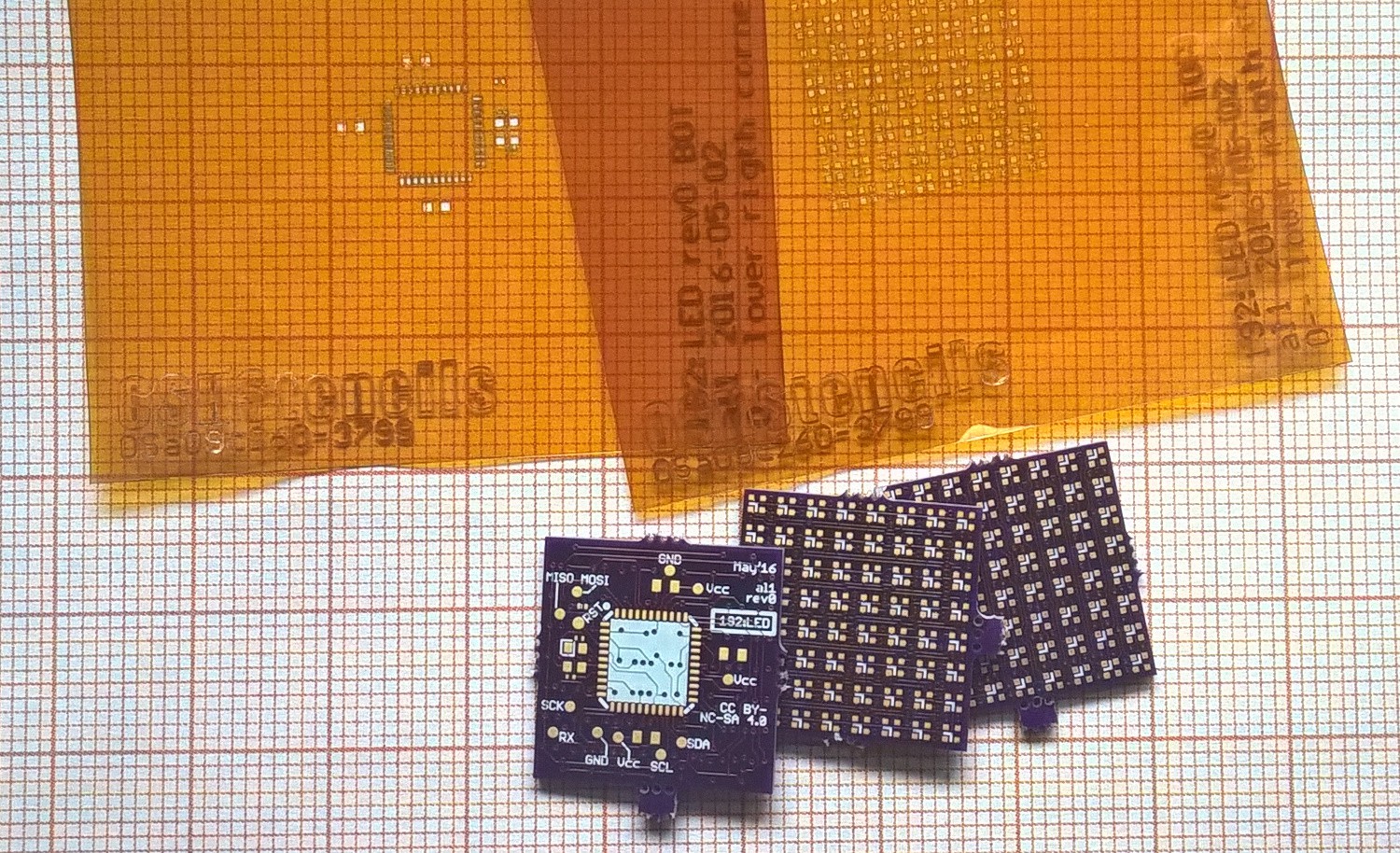
 On the left is a photo the right is the rendering. Luckily I found a real ¼US$ coin at home.