Close
0%
0%

DC-10

My implementation of C10 decimal time clock

Similar projects worth following
The C10 is a time system proposed by KNIVD and provides a base10 way of counting the time. In this sytem a whole day is divided into 100 intervals which are subsequently divide into 100 minor intervals named 'centivals' wich in turn are divided into 100 'ticks'.
The present project is my implementation of a clock using such system with 4 digits thus capable of showing 'intervals' and 'centivals'.

In the decimal time system a whole day (24 hours) is divided into 100 intervals which are subsequently divide into 100 'centivals' wich in turn are divided into 100 'ticks'.

Using more familiar base12 time base as a reference we have:
1 tick = 86,4ms
10 ticks = 864ms = 0,864 seconds (a bit less than a second)
100 ticks = 8,64 seconds = 1 centival
1000 ticks = 86,4 seconds = 10 centivals (1 minute and 26 seconds)
10000 ticks = 864 seconds = 1 interval (14 minutes and 24 seconds)
10000 ticks = 8640 seconds = 10 intervals (2 hours and 24 minutes)
100000 ticks = 86400 seconds = 100 intervals (24 hours)

This project implements a very simple digital clock with 4 digits capable of showing centivals and intervals. The least significant digit changes each centival (8,64 seconds) and the most significant turns every 10 intervals (2 hours and 24 minutes)

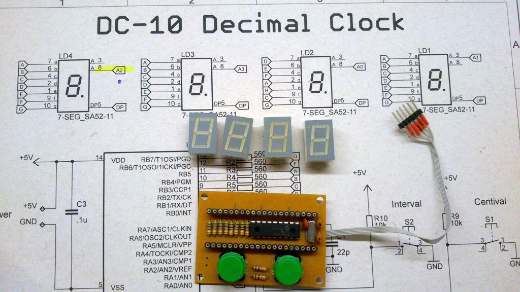
The circuit is based on a PIC16F628 and four 7-segment displays in a conventional multiplex configuration. One of the displays is turned upside down so we can have two decimal points to separate intervals from centivals.

The timebase is provided by a 4.0Mhz crystal which generates a tick (86,4ms) using a Bresenham algorythm (code borrowed from Roman Black). As a result we have some microseconds of jitter yet imperceptible to the eye.

Each display is turned on by 4ms at a time which gives an overall display refresh rate of 16ms or ~60Hz in terms of frequency.

There are two buttons to adjust the time. One is for advance the centivals while another advances the intervals.

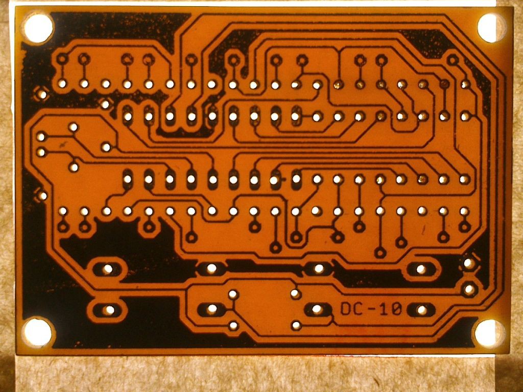
The circuit board measures 60x42mm (2.35" x 1.65") and it was designed to be single face friendly with few connections on the upper side and no connection on the top layer is hidden under any component.

The firmware uses the timer0 running at 1:1 thus overflowing exactly each 256us. At every 16 interrupts or 4096us a flag is set to allow the main loop to run. Another flag is set at each tick (86.4ms) and tells the main loop to increment the tick counter. At 100 ticks the main loop calls the function to increment the centivals and after 100 centivals another function is called to increment the intervals. Functions were used to implement the increments to make easy to perform the increments when commanded by the buttons.

An alternative approach would be to increment an int32 variable and convert then to string using itoa() and then updating the display variables based on the ascii codes of each number.

dc10.hex

hex file, ready to be flashed on the PIC16F628

hex - 4.11 kB - 12/03/2016 at 19:05

Download

  • 1 × PIC16F628 Microprocessors, Microcontrollers, DSPs / ARM, RISC-Based Microcontrollers
  • 4 × .56" 7-segment display
  • 8 × 150R 1/4W
  • 2 × 10K 1/4W
  • 2 × 12mm Tactile Swich

View all 8 components

  • Python Clock: Now with HAD colors

    danjovic12/04/2016 at 20:03 0 comments

    Changed the colors to be like Hackaday theme!

  • DC-10 clock Python

    danjovic12/04/2016 at 17:50 0 comments

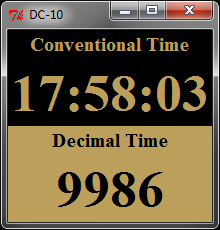
    Python Rocks!! You can code many things by example like this dual clock with both the conventional and decimal time. It is worth to mention that I am using 06:00 (AM) as the start of the decimal day instead of midnight. For me it makes more sense that "DAY" coincides with "DAYLIGHT".


  • It's alive!

    danjovic11/28/2016 at 03:38 0 comments

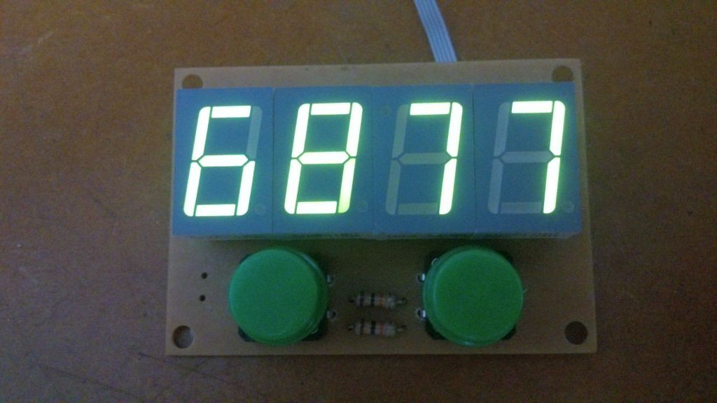
    The assembled board is now working! It was necessary to change the code to match the common cathode displays. I am considering to add a compiling directive to select whether to use common anode or common cathode.

    The green display was too dim with the original 560 Ohms resistor. I needed to change them to 150 Ohms and the brightness is much better now.

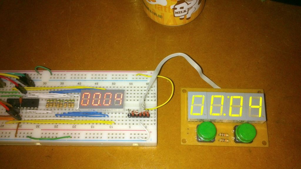
    Both the prototype and the finished board are working now.

  • Assembled Board

    danjovic11/27/2016 at 15:49 0 comments

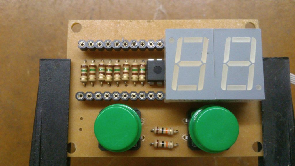
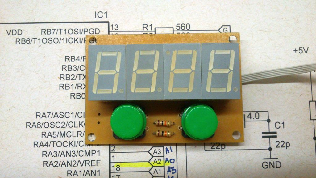
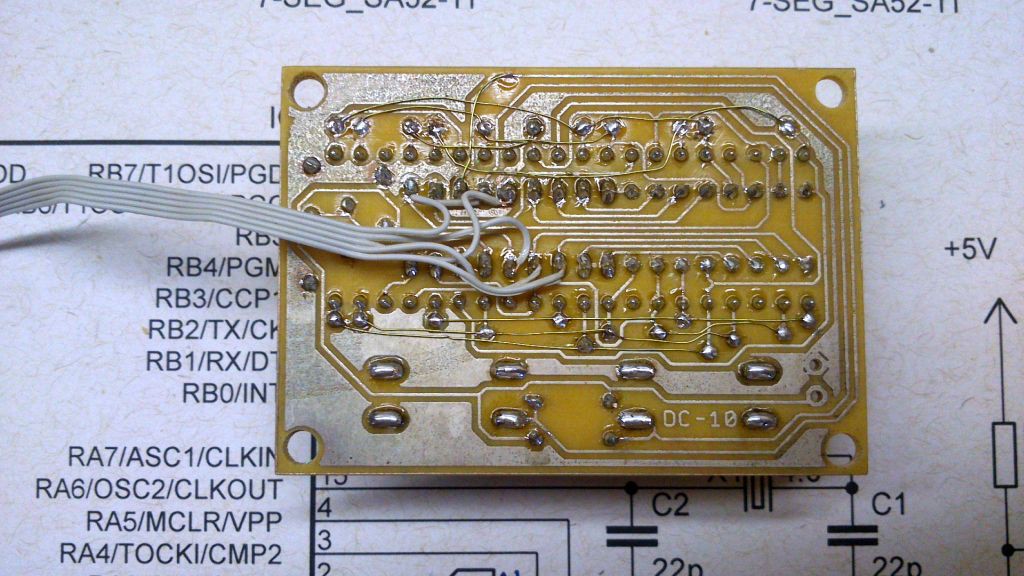
    Just finished assembling the board for DC-10.

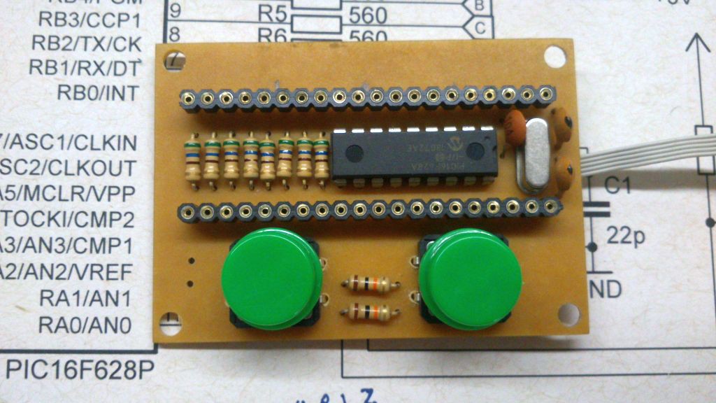
    The displays are mounted on sockets and the microcontroller as well as the current limiting resistors are mounted underneath.

    The third display is mounted upside down so its decimal point together with the decimal point from the second display can form a colon ( ":" ).

    The enamel wiring is placed instead of the top layer and the thin flat cable is connected to the programming pins of the pic.

  • Making a PCB at home

    danjovic11/27/2016 at 15:09 0 comments

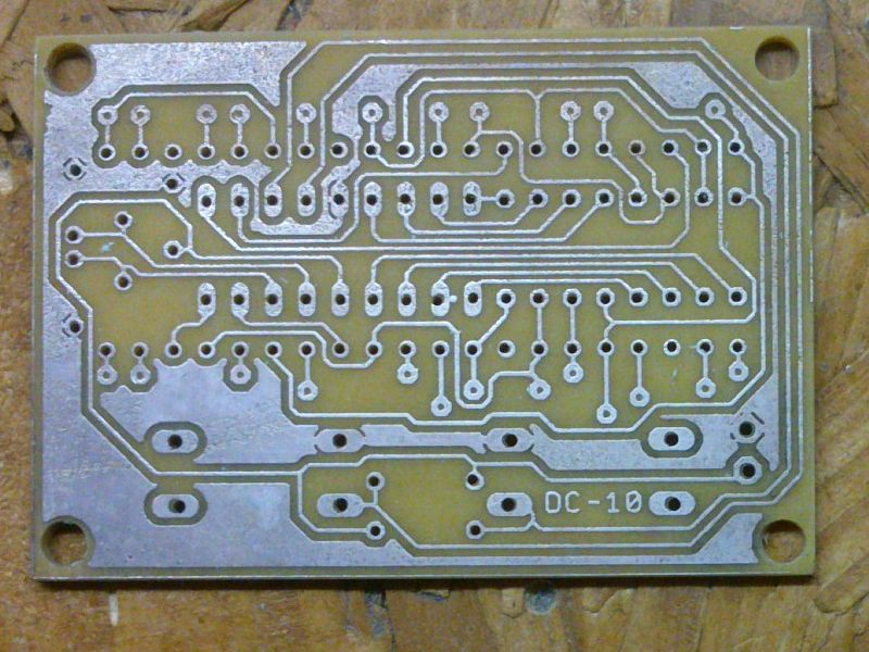
    I made this PCB at home using toner transfer. I definitely have to use a better paper than ordinary magazine sheets! Nevertheless the result is acceptable.

    This board should be double side but there are few connections on the top layer then I decided to leave the vias undrilled and complete the circuit using enamel wire.

  • First prototype

    danjovic11/26/2016 at 04:40 0 comments

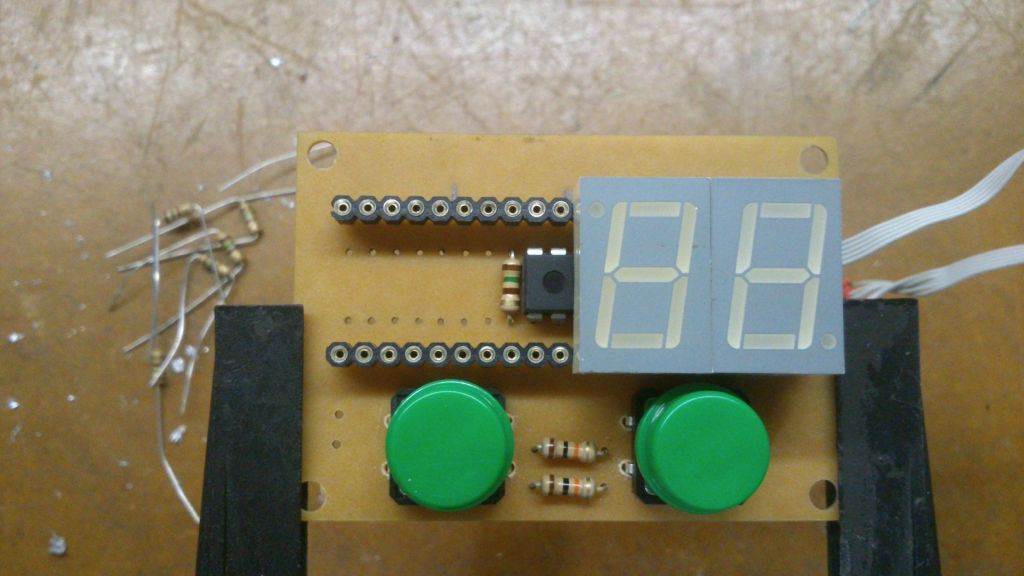
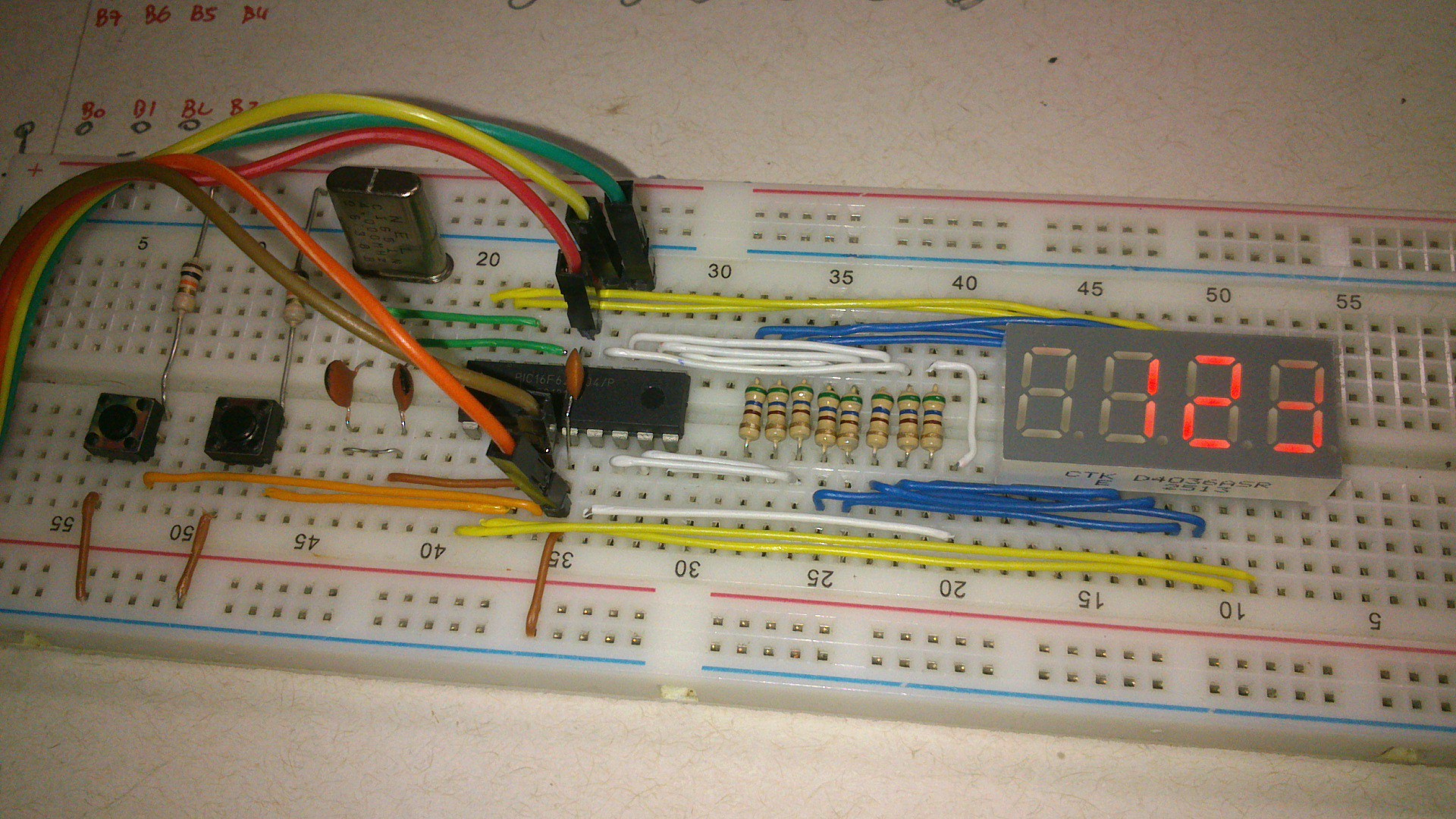
    Successfully assembled the prototype of the DC-10 clock.

    But not everything went as I've expected.... The PC in my workshop can no longer run MPLAB 8.2 and I could not find a way to fix it and after some time I gave up and started to port the code to SDCC.

    After some research using Google I was able to compile the code and run on the PIC16F628. The main difference from using CCS C to SDCC are the fuse bits configuration , the declaration of the interrupt vector and some standard types (like int32 vs uint32_t).

    I needed also to change the definition of the digits to match the assembled prototype, since the connection to the segments were made to optimize the wiring and did not followed the original diagram.

    The size of the compiled code is shown at the end of the assembly listing. There is an estimative of how many bytes the code is using but it seems that SDCC computes 20 bits for each instruction.

    ;	code size estimation:
    ;	  278+   80 =   358 instructions (  876 byte)
    It is very interesting to see the time flowing in the decimal system. Now I want to take it to the work and see how do I behave using the decimal clock as a reference.

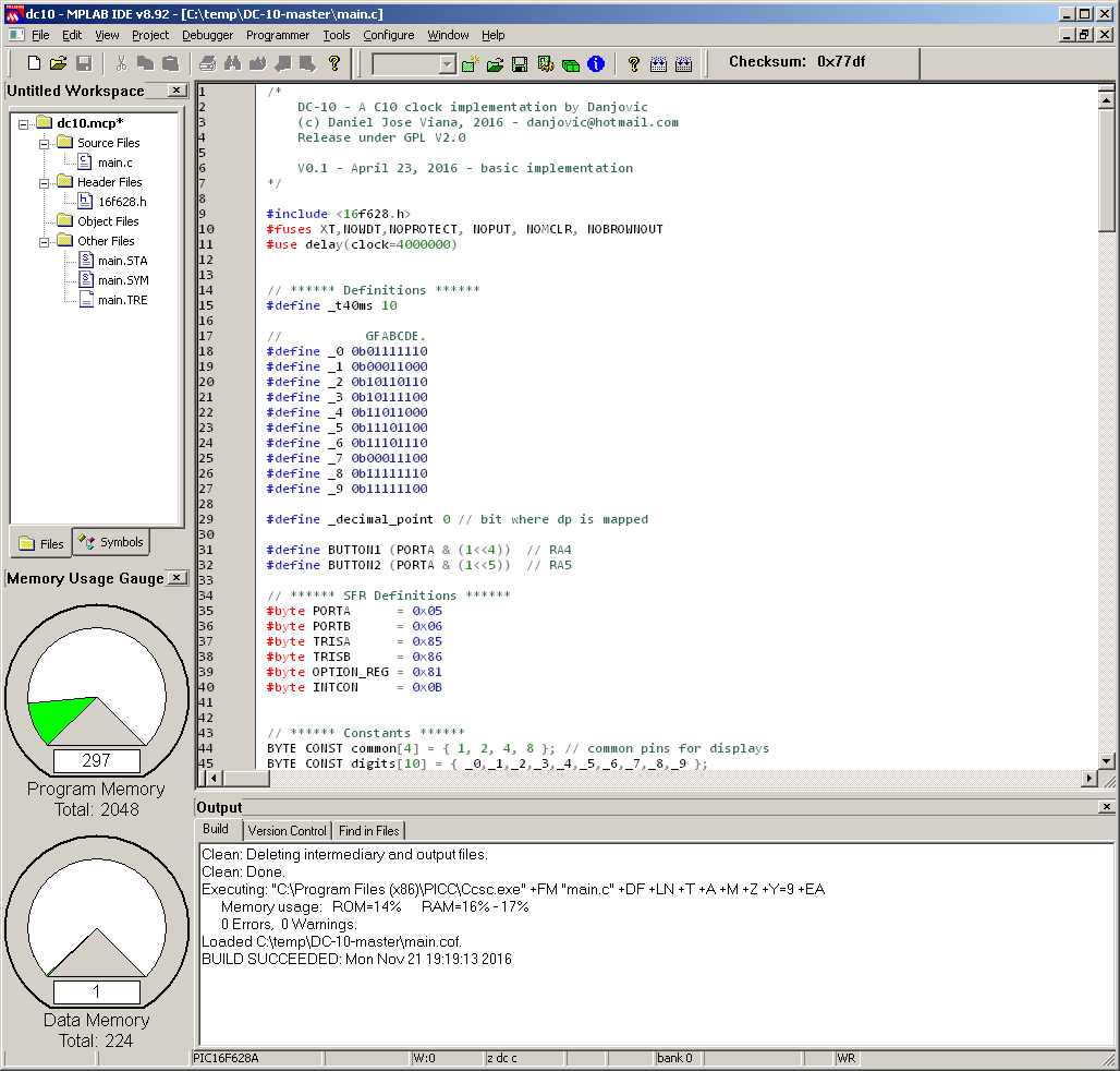
  • Entry for 1K challenge

    danjovic11/21/2016 at 21:20 0 comments

    This is my second entry for the challenge. Only 297 words of code (roughly 520 bytes).

View all 7 project logs

  • 1
    Step 1

    The code is available at my github repository (link).

    To compile the code it is necessary to have SDCC installed. When using SDCC in Linux it is necessary to generate the header files from the Microchip include files (link)

    compile the code just type the following command:

    sdcc --use-non-free -mpic14 -p16f628 main.c -o "dc10"

    It will generate the "dc10.hex" file that can be then flashed on the microcontroller.

View all instructions

Enjoy this project?

Share

Discussions

Jan wrote 02/20/2017 at 15:31 point

Nice project! I'm always amazed at how many possibilities there are to display time!

  Are you sure? yes | no

danjovic wrote 02/20/2017 at 21:36 point

Thanks! I am very fond of timepiece mechanisms and their numbering systems. I am considering to build a clock like yours but using regular LEDs and shift registers.

  Are you sure? yes | no

Kn/vD wrote 01/17/2017 at 19:38 point

Beautiful job! :-)

  Are you sure? yes | no

danjovic wrote 01/17/2017 at 20:00 point

Thanks!  I have just implemented your idea!

  Are you sure? yes | no

Kn/vD wrote 01/17/2017 at 20:25 point

You implemented it better :-)
I actually never finished the firmware of mine. Still at 80% for the past few months...

  Are you sure? yes | no

O. Alan Jones wrote 12/03/2016 at 14:34 point

Congratulations on your DC-10 project! I like the way you installed your 4 displays on two headers over the circuit.  The PIC16F628 is my favorite microchip so far. Which C compiler did you use to program your PIC?

Good job on building your own pcb. It is a lot of fun and rewarding to be able to make your own pcb. I still have not made a double sided board yet. Rather than use magazine paper I use Hammermill Laser Gloss Paper. The paper works great for toner transfer.

  Are you sure? yes | no

danjovic wrote 12/03/2016 at 18:57 point

Thanks Alan! I've started with CCS C, but needed to port the code to SDCC because MPLAB 8.2 was crashing on my computer. You can check the code at https://github.com/Danjovic/DC-10/tree/master/firmware/sdcc . Use compile.bat to compile the code or just type the following line:

sdcc --use-non-free -mpic14 -p16f628 main.c -o "dc10"

  Are you sure? yes | no

Kuro wrote 11/21/2016 at 21:40 point

Belo DC-10. Saudades da Varig.

  Are you sure? yes | no

danjovic wrote 11/22/2016 at 03:27 point

Pois é, não resisti à coincidência do nome e coloquei um banner em homenagem ao avião.

  Are you sure? yes | no

Similar Projects

Does this project spark your interest?

Become a member to follow this project and never miss any updates