-
Python Clock: Now with HAD colors
12/04/2016 at 20:03 • 0 commentsChanged the colors to be like Hackaday theme!
![]()
-
DC-10 clock Python
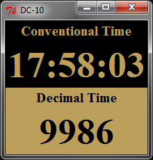
12/04/2016 at 17:50 • 0 commentsPython Rocks!! You can code many things by example like this dual clock with both the conventional and decimal time. It is worth to mention that I am using 06:00 (AM) as the start of the decimal day instead of midnight. For me it makes more sense that "DAY" coincides with "DAYLIGHT".
![]()
-
It's alive!
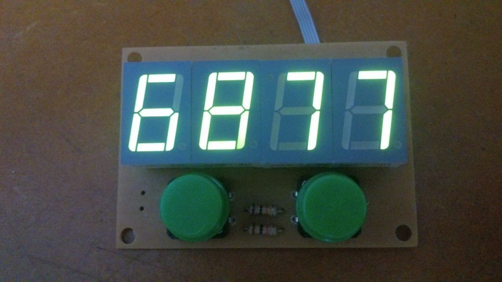
11/28/2016 at 03:38 • 0 commentsThe assembled board is now working! It was necessary to change the code to match the common cathode displays. I am considering to add a compiling directive to select whether to use common anode or common cathode.
![]()
The green display was too dim with the original 560 Ohms resistor. I needed to change them to 150 Ohms and the brightness is much better now.
![]()
![]()
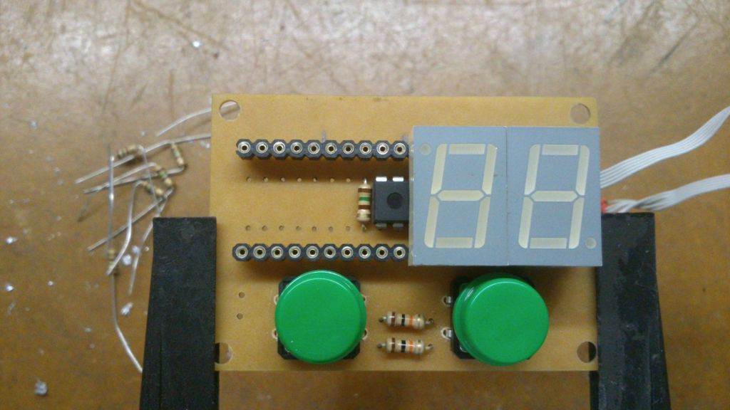
Both the prototype and the finished board are working now.
![]()
-
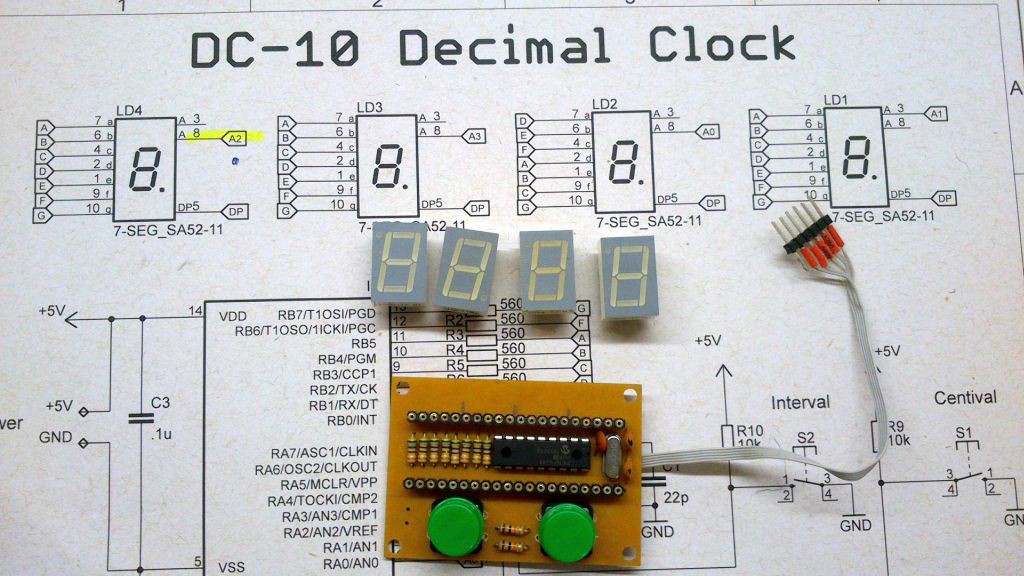
Assembled Board
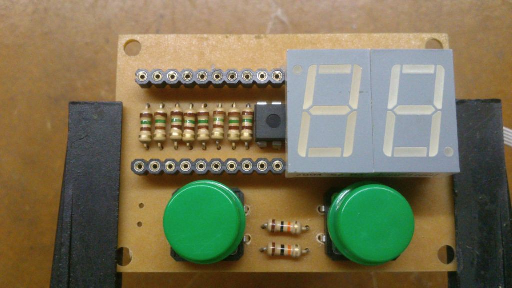
11/27/2016 at 15:49 • 0 commentsJust finished assembling the board for DC-10.
![]()
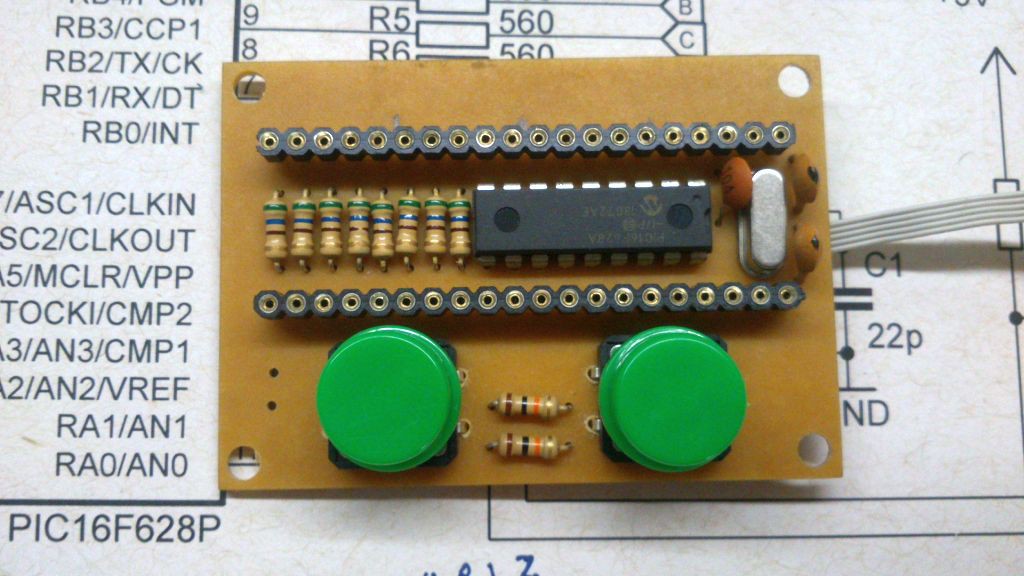
The displays are mounted on sockets and the microcontroller as well as the current limiting resistors are mounted underneath.
![]()
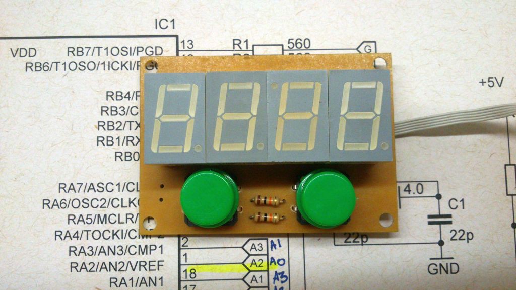
The third display is mounted upside down so its decimal point together with the decimal point from the second display can form a colon ( ":" ).
![]()
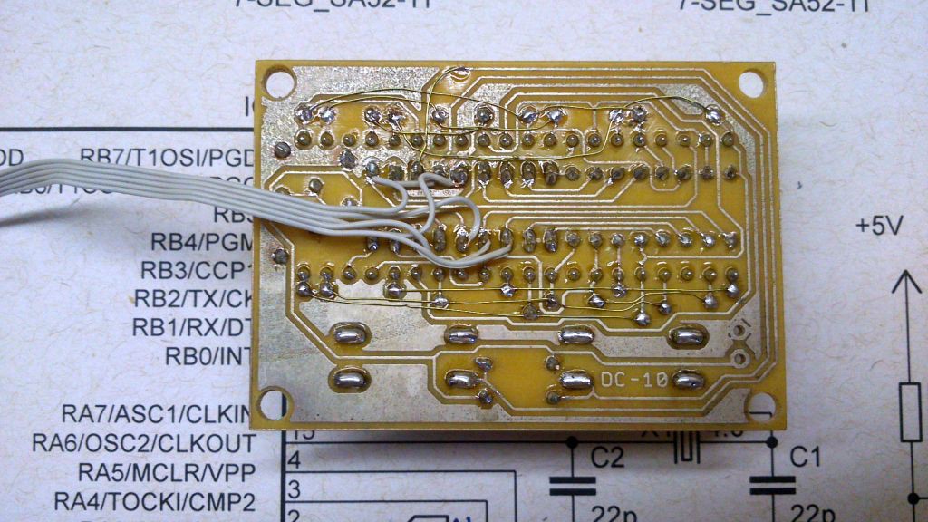
The enamel wiring is placed instead of the top layer and the thin flat cable is connected to the programming pins of the pic.
![]()
-
Making a PCB at home
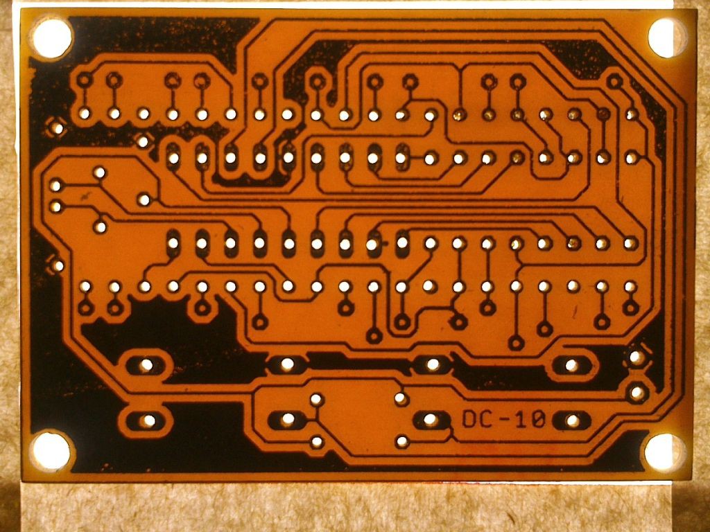
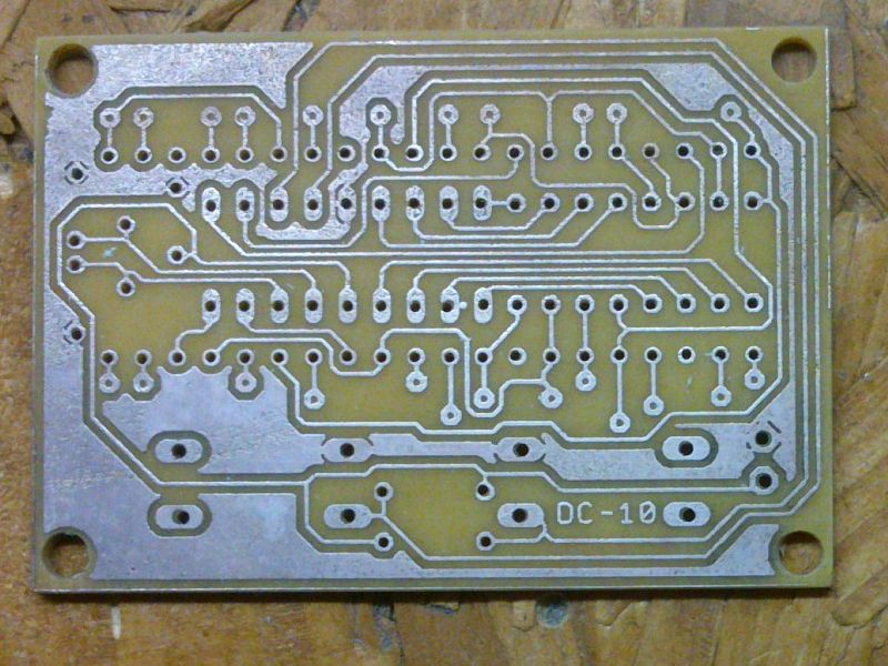
11/27/2016 at 15:09 • 0 commentsI made this PCB at home using toner transfer. I definitely have to use a better paper than ordinary magazine sheets! Nevertheless the result is acceptable.
![]()
This board should be double side but there are few connections on the top layer then I decided to leave the vias undrilled and complete the circuit using enamel wire.
![]()
-
First prototype
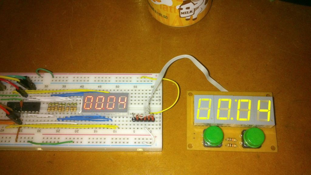
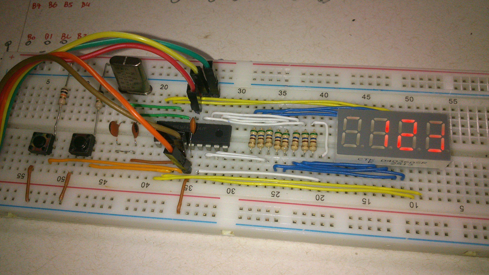
11/26/2016 at 04:40 • 0 commentsSuccessfully assembled the prototype of the DC-10 clock.
![]()
But not everything went as I've expected.... The PC in my workshop can no longer run MPLAB 8.2 and I could not find a way to fix it and after some time I gave up and started to port the code to SDCC.
After some research using Google I was able to compile the code and run on the PIC16F628. The main difference from using CCS C to SDCC are the fuse bits configuration , the declaration of the interrupt vector and some standard types (like int32 vs uint32_t).
I needed also to change the definition of the digits to match the assembled prototype, since the connection to the segments were made to optimize the wiring and did not followed the original diagram.
The size of the compiled code is shown at the end of the assembly listing. There is an estimative of how many bytes the code is using but it seems that SDCC computes 20 bits for each instruction.
;	code size estimation:
;	  278+   80 =   358 instructions (  876 byte)
It is very interesting to see the time flowing in the decimal system. Now I want to take it to the work and see how do I behave using the decimal clock as a reference. -
Entry for 1K challenge
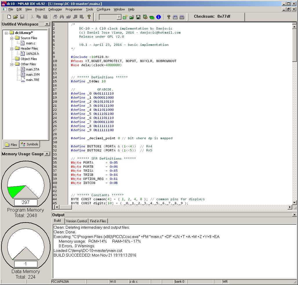
11/21/2016 at 21:20 • 0 commentsThis is my second entry for the challenge. Only 297 words of code (roughly 520 bytes).
![]()
 danjovic