-
README
04/19/2019 at 02:29 • 0 comments# MUVeC
Modular Unmanned Vehicle ControllerThis project was created in 2009 to develop an unmanned vehicle control system for
scientific purposes. I wanted to develop not only software but also a reliable hardware
which should be capable of handling redundancies and, most important, which should be
easily upgradable. New sensors and microcontrollers seem to be created frequently and,
to deal with that, I made my system modular.In the beginning there were many modules planned and I wanted to make them as cheap
and flexible as possible. Using my very limited knowledge of electronics, I selected
an ATMEL MCU which was the base of the Arduino. I rewrote a lot of code, dividing
solutions into libraries that focused on simple problems.I tried to define a few standards on the hardware like PCB sizes, module and submodule
connections, inter-module communication interface etc. Then those decisions were
transported to the code, which despite all the alerts from the AVR development community,
was written in C++.Everything evolved slowly through four versions until the system converged to a working
solution on version 5, which used an SPI interface to connect modules and a locally developed
protocol to manage long data transfer between them without errors.Version 5 depended on a communications module which interrogated every slot of the main
bus asking if there was a module plugged there and which were its capabilities. A matrix
was created with the obtained data with enough information for the module to take decisions
on which module should be interrogated in each system state to make the information flow
from sources to destinations. Amazingly, it worked. This solution made it possible to
create modules with mixed capabilities, like inertial sensing and piloting, and absorbing
all of the in the system. It also made possible to handle, in the future, the existance
of many sensor modules and many pilots in the same system. This opened the door for
critical fault handling.Version 5 though, had its own limitations, like the mechanical coupling between modules
and main bus which was very bad. Vibrations from the engines of a tricopter affected the
sensor module and messed the readings. A few other problems were detected and I decided
to solve them on version 6.On this new version I changed the MCU to a STM32F3, which is way more powerful than the
ATMEGA328P. The new PCBs gained more space and a much better way to couple them mechanically.
Inter module communication was moved to a CAN interface. Everything now is faster
and more powerfull. -
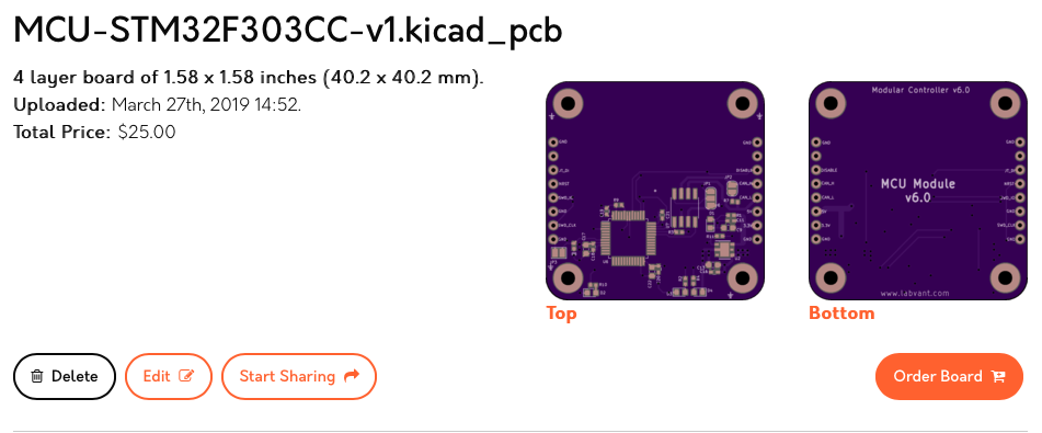
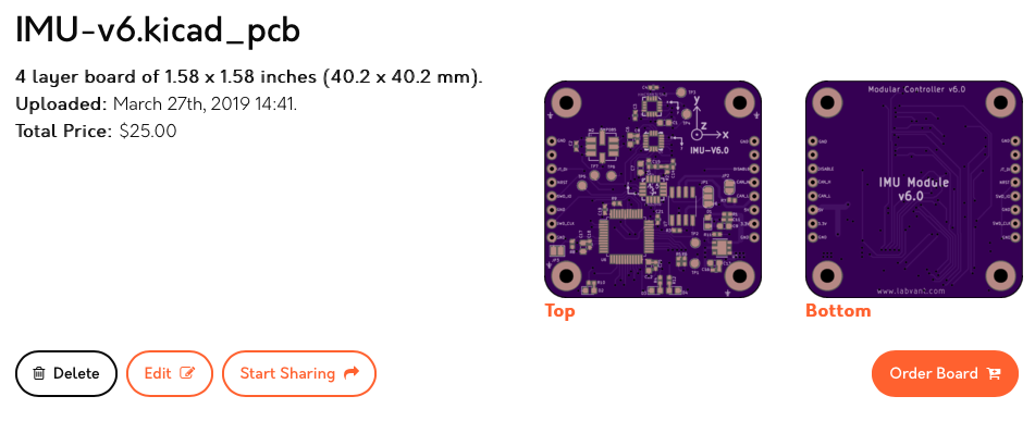
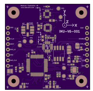
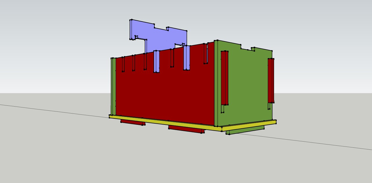
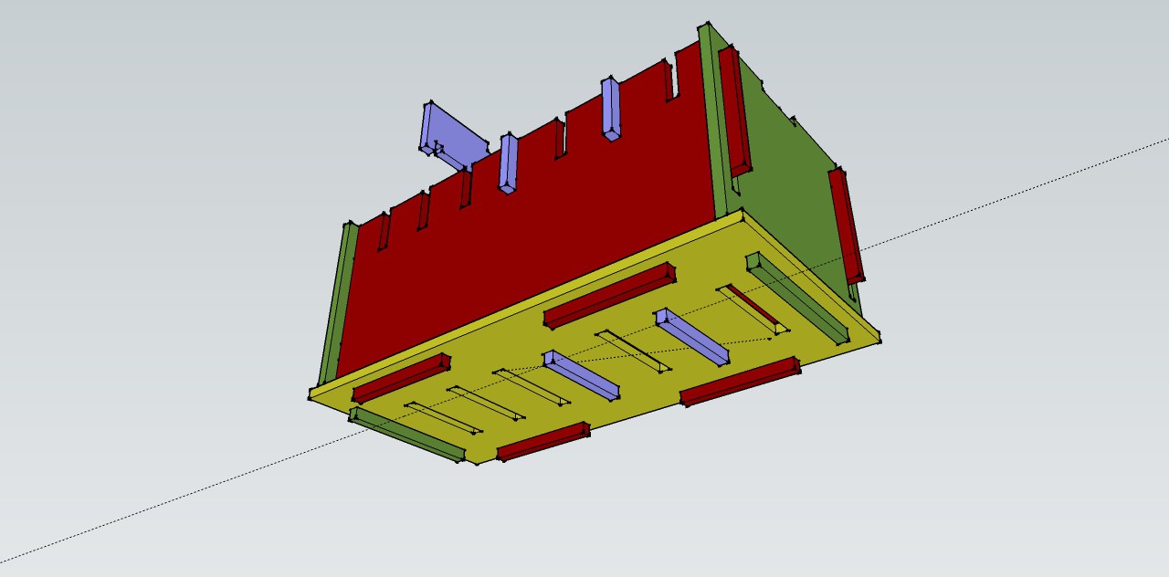
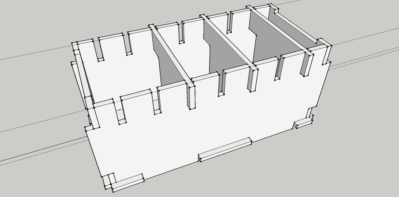
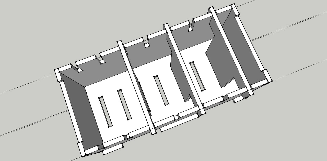
Next version PCB candidates
03/27/2019 at 14:57 • 0 comments![]()
![]()
![]()
![]()
-
Version 6 modules, now talking CAN and using STM32.
03/26/2019 at 13:59 • 0 commentsI'm working on version 6 of the system modules. They are STM32 based and use CAN to talk to each other. There will be five modules: communication, servo, IMU, a blank MCU and a power supply one. Form factor has changed too. Now they have 4cm x 4cm.
This version solves mounting issues, makes the communication between modules much easier and even let you use them for other purposes by connecting them to other stuff via the widely used CAN interface.
Soon I'll post the link to OSH park and a Mouser BOM, so you can build yours at home too.
![]()
-
Tricopter simulation
02/14/2019 at 15:04 • 0 commentsAfter moving to another city, the development of the system PCBs had to be halted for some time. Due to a lack of space, I had to focus most of the work on this project on the computer. My new job created an opportunity to revive a n-body simulation program I have written during the physics course, around the 90s. This program allowed me to simulate configurations of particles and springs interacting through well known laws and visualize them through virtual 3D cameras. I upgraded it to run on multiprocessor machines and moved all the code to C++, using SDL as a plotting tool and CERN ROOT to plot graphs.
Testing the real tricopter became a dangerous task. The control system PIDs need to read sensor data and control engine power. I had to tie the tricopter to a string connecting the room ceiling to a 20kg water bottle that was hanging on it. When the control system was turned on, the engines could go to maximum speed and destroy something around, even with the tricopter tied. Testing the control system in a real system proved to be tricky.
I decided to unite both efforts and build a simple tricopter model on the simulation program. I used a four particle model with particles connected by hi-K springs. Three particles behaved as the three engines, the fourth behaving as a payload. Their relative positions can be controlled by parameters.
The forces that are applied on the three engine particles are the near same forces that would apply to the engines. And they would be defined by the PIDs that control the real tricopter. A servo was simulated to deflect the tail engine air flow and counteract residual torque. By monitoring the tricopter gravity center and particle configuration I could calculate the sensor data thus simulating a magnetometer, an accelerometer and a gyroscope. A virtual planet was also simulated to give me geographical coordinates for the simulated GPS and a magnetic field for the magnetometer.
Tuning the PID parameters on the simulated system proved to be as difficult as doing it in a real system. The good part is that I would not hurt my fingers on real propellers. After many, many tries and different PID connection configurations, I reached a more or less stable system and decided to code some genetic algorithm programing on the simulation. Now I had populations of tricopters that tried to stay near a waypoint as long as possible. The best of them was used as a seed for the next generation. PID gains were perturbed along the population to generate more or less adaptable individuals.
It turned out that a perturbing many parameters at a time, even slightly, did not produce optimal results. The selection process was taking many generations to produce a better individual, and its performance was far from the one I expected, so I decided to restart tuning the PIDs of a single individual manually. I also changed the PIDs arrangement, to use the maximum amount of sensor information I could.
Today I believe to have reached a milestone. The video below shows the latest result. The red cross is the tricopter waypoint, which is moving because the small planet below it is rotating slowly. The forces produced by the engines are plotted in white, while the control system desired heading is shown in red or blue, depending on the distance to the waypoint.
Now I believe this control code can be used on the real tricopter system.
-
Telemetry and module capacity matrix
09/10/2017 at 17:00 • 0 comments![]()
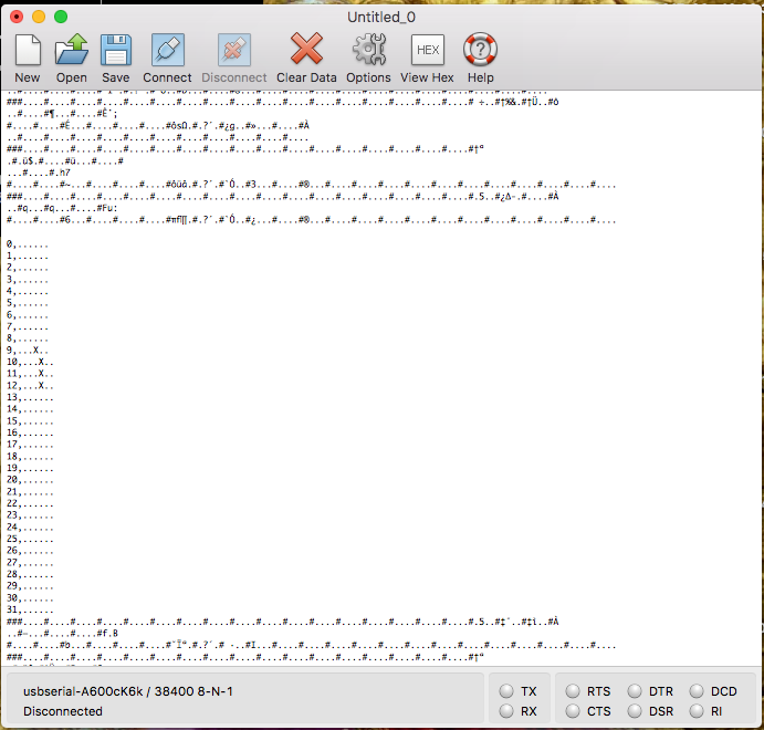
Today I'm posting a picture of the CoolTerm terminal connected to the communications module via a serial connection.
What can be seen are many telemetry sequences starting with ### and using # as a separator between the four bytes that represent each relevant system variable value. I made a small C++ program to parse the telemetry and show the data on the screen.
![]()
A tall matrix can be seen on the serial terminal too. Each line of the matrix represents a capacity that an installed module can have. Modules can have accelerometers or other sensors installed, for example. Or they can be able to pilot the vehicle, or they can control servos. All the current capacities are listed in the following link: https://pastebin.com/KBw1i5Ui
The matrix shows that the module installed on slot 4 have an accelerometer, a gyroscope, a barometer and a magnetometer.
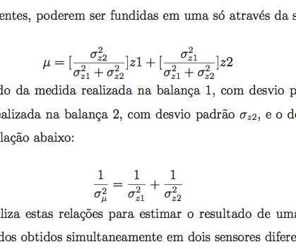
By using a matrix like this the data from similar sensors can be fused together using this equation:
![]()
And this operation can be done in a simple loop, taking care of the possibility of sensor redundancy in a very simple way.
Your comments are important and welcome.
You can find me online on the #avr and #sparkfun channels of the Freenode IRC servers. People from those channels are very nice and have contributed with solutions to programming problems and hardware related ones.
-
Laser cutting a prototype on paper
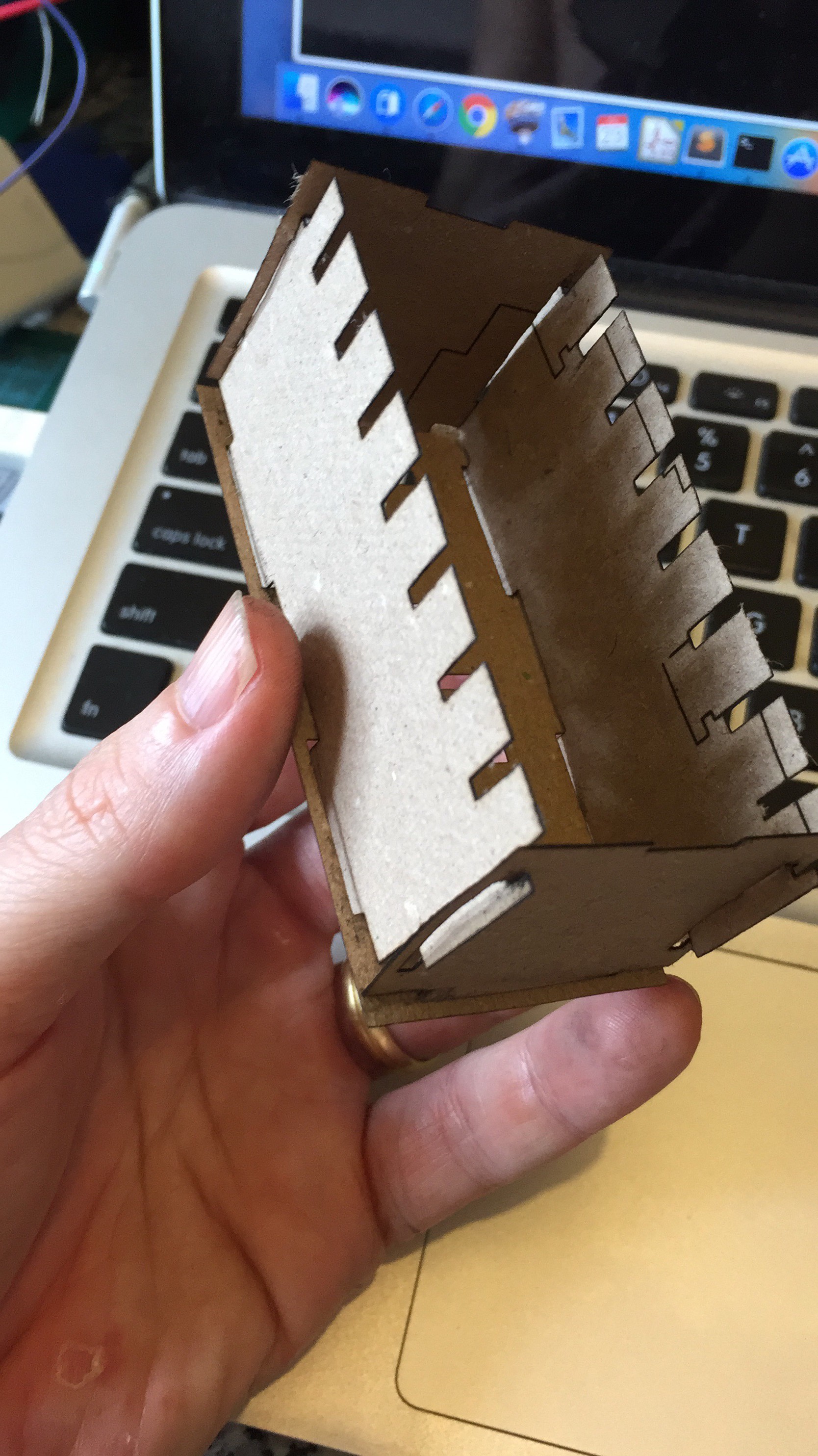
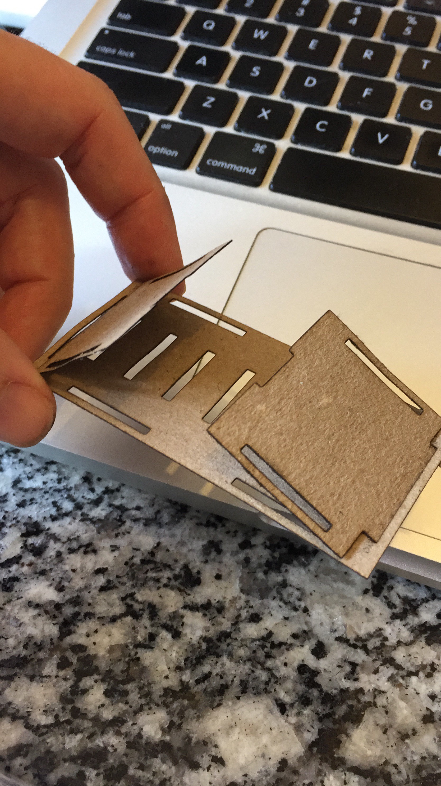
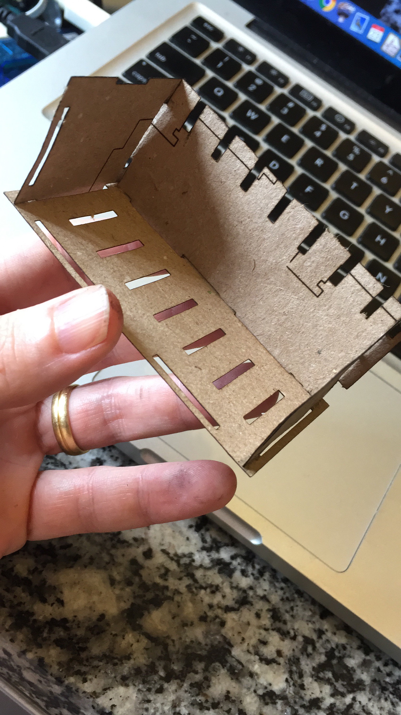
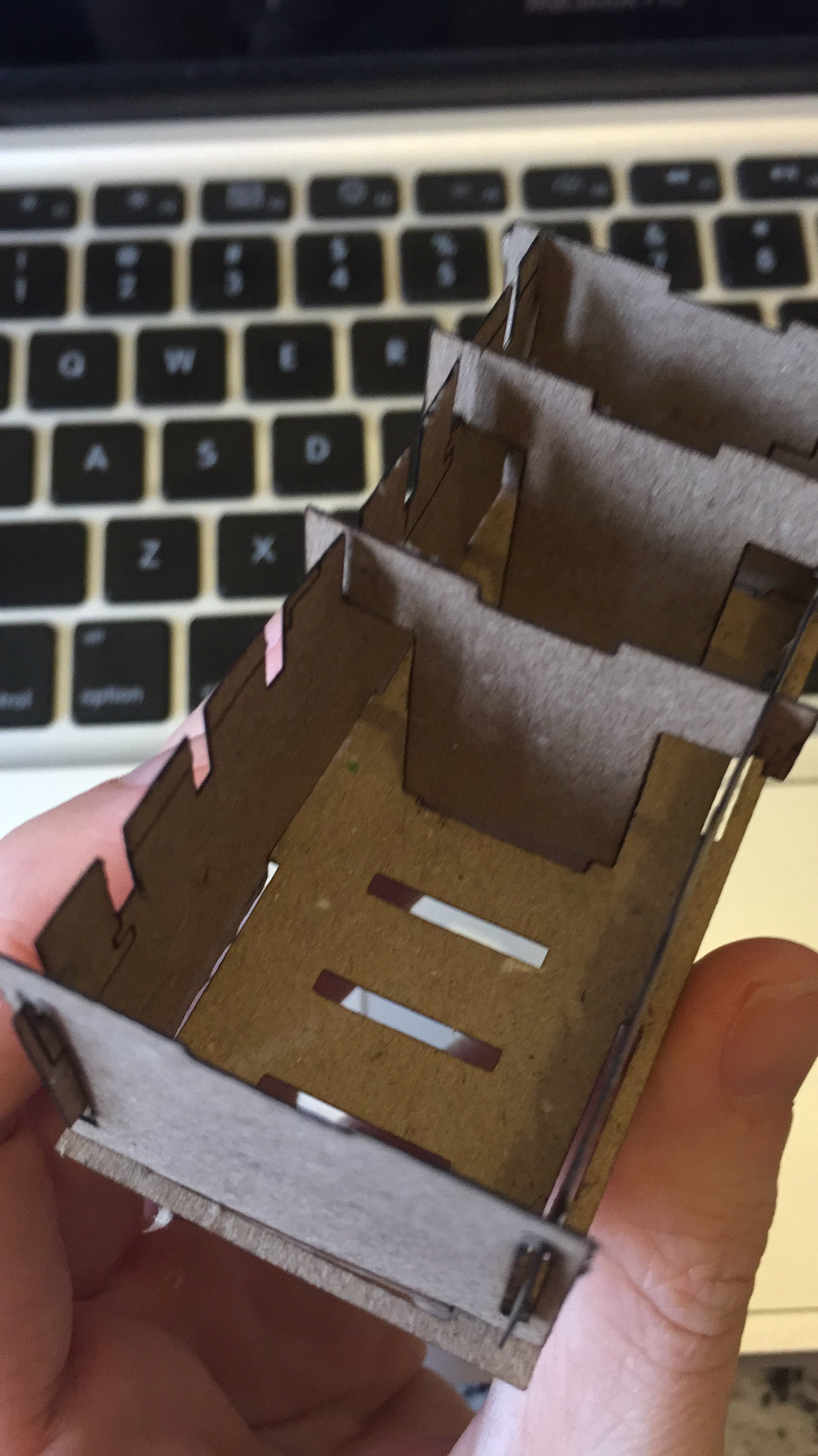
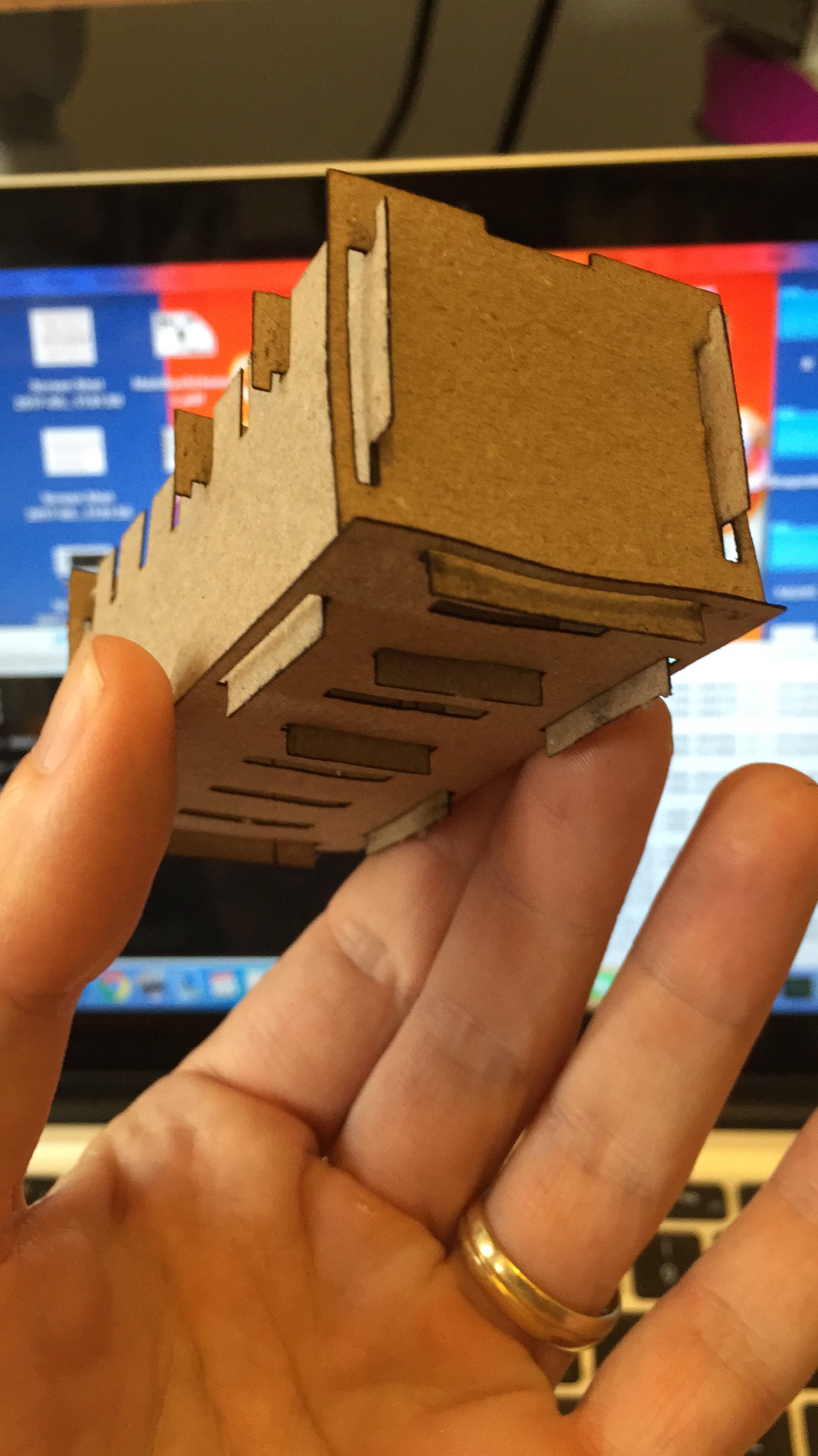
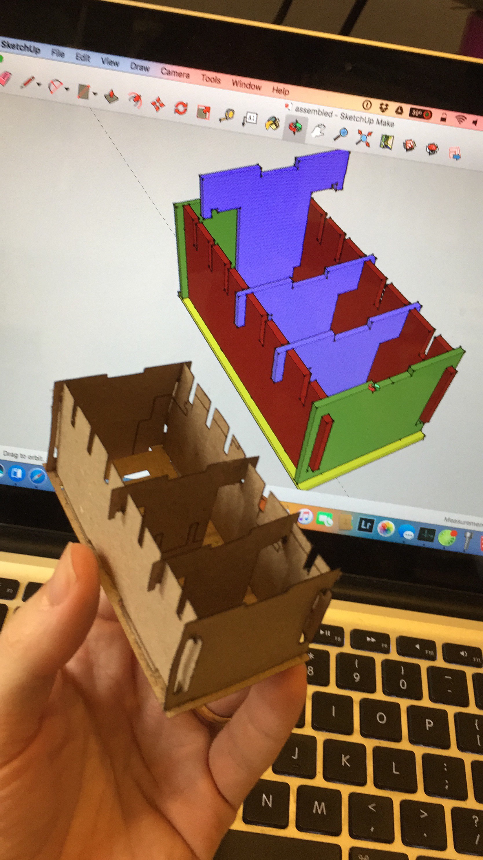
07/23/2017 at 19:44 • 0 commentsHi. I tried to laser cut a prototype of the possible new PCBs on paper. The results are shown below:
As I'm using a very low power (500mW) 808nm laser diode, the cutting speed must be very small (25mm/min), so patience is a must.
Parts were drawn on Sketchup, exported as STL and converted to G-Code using MeshCAM. They were fed to the CNC controller (tiny-g) using a software I made and called YetAnotherGCodeSender. Source code is publicly available. The CNC is a modified ShapeOko2.
Here is the pre-assembling:
And this is the final result:
As always, your comments are welcome!
-
2nd candidate for new PCB set.
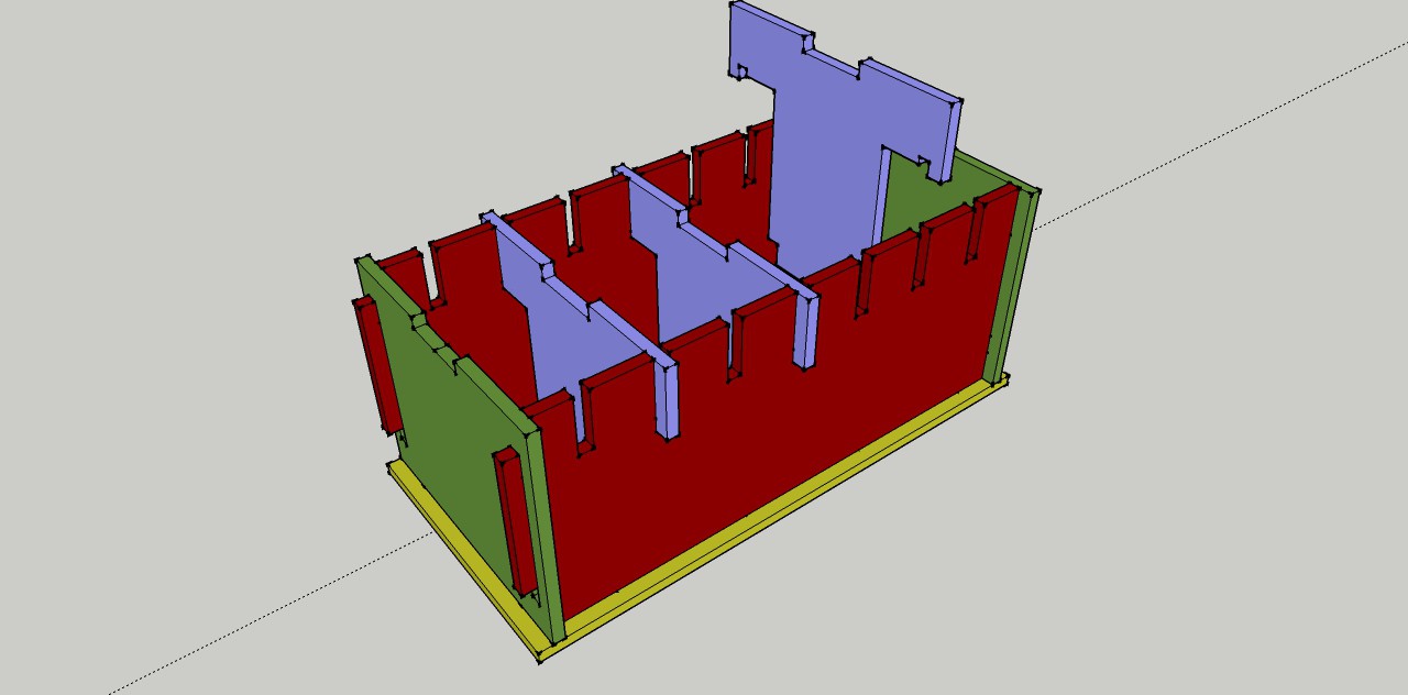
07/20/2017 at 02:04 • 0 commentsHello. After many suggestions and critics, this is the second candidate for the next generation PCB set. Please let me know what you think. This version is mechanically interlocked to increase strength and reduce the stress on the joining solders.
![]()
![]()
![]()
-
I need your advice!
07/19/2017 at 16:02 • 0 commentsHi.
I'd like to ask your opinion about the following drawings. I'm thinking of designing the new generation of project PCBs in the way displayed below.
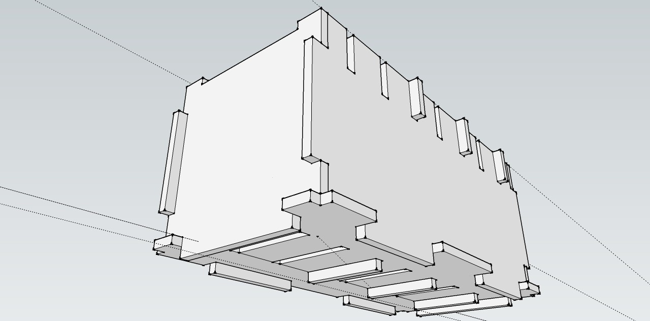
Making them like that would enable me to use the PCBs as PCBs and as a structural support for the modules, with the benefit of eliminating the annoying module connectors and module vibration.
![]()
![]()
![]()
All the displayed parts are PCBs. They would be mechanically attached to each other using the slots and fixed in position using solder pads. Modules would be electrically connected to the box using solder points on the bottom and on the sides, which could also carry more connections such as a redundant power rail, or a redundant SPI bus. Modules would also gain more space, being able to grow a bit to the sides if needed.
I need your expertise. You have a unique view about this possibility and can help a lot this project by sharing it here. Please let me know what you think.
-
Servo control module tests
06/25/2017 at 04:05 • 0 commentsAfter a lot of testing and debugging of the servo module, I discovered I made a horrible mistake in the module project. I forgot the I2C pull-up resistors. Fixing it was not easy, but was done. I soldered two 10k resistors over the SDA and SCL lines of the servo module and connected them to the 3v3 line. Another big problem I faced was the PCA9685 I2C addressing which was calculated in the wrong way by me. The logic level analyzer I bought at DX.com for 9USD helped a lot to find and fix the error.
It the spare time of two weeks to find and fix all the errors, but now the module has 16 working PWMs ready to control the servos.The prototype can be seen working in the video below.
Next step is to plug the module in the YAUVC backbone and start controlling it via WIFI, or let the flight control module take care of it.
-
Introducing the YAT: Yet Another Tricopter
06/06/2017 at 01:10 • 0 commentsHello!
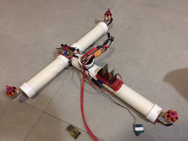
Today I managed to put everything done until now together, building what is now called the YAT: Yet Another Tricopter!
The thing has three electric motors, three ESCs, one servo, a switching 3.3V power supply (the 3.3v module is flawed), and the YAUVC backbone with some modules. This platform will work as a testbed for the servo control module and for the control algorithms that will try to make the YAT fly. Instead of the battery, I connected the YAT to a power supply via a cable. Communication to the YAUVC is done via WiFi. Here are some pictures:
Next step is to develop the code for the servo control module.
![]()
Soon I hope to come back with more good news.
And, if you want to follow this project more closely, you can join the @labvant.com Telegram group, where I'll be posting more frequent updates and pictures.
Thanks again for all your help and support!
Modular Unmanned Vehicle Controller
(former YAUVeC - Yet Another Unmanned Vehicle Controller)
 E. N. Hering
