E. N. Hering
-
Good news!
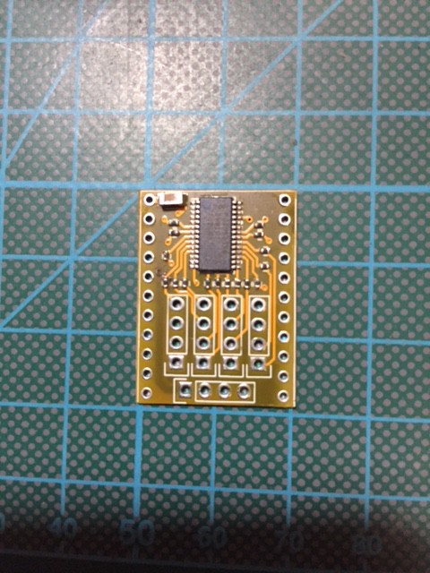
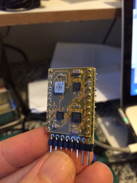
06/01/2017 at 01:22 • 0 commentsAfter five months traveling at the back of a drunk snail, the components I ordered from China have finally arrived. Today I managed to assemble the servo control submodule and here is the first picture of it:
![]()
This submodule is controlled by the MCU module via a two wire interface (TWI). The MCU module talks to the rest of the system via a SPI interface available from the main bus. The submodule have 16 pins to connect to the servos. They are the ones in a 4x4 matrix. The four pins below them are connected to 5V and ground.
Having 16 servo plugs directly available on this PCB would make it too big to fit into the system. I decided to interface servo plugs with this board elsewhere. This will require some wires to be soldered to this board with male servo connections on the other end. The number of wires will depend on the required number of servos for each project.
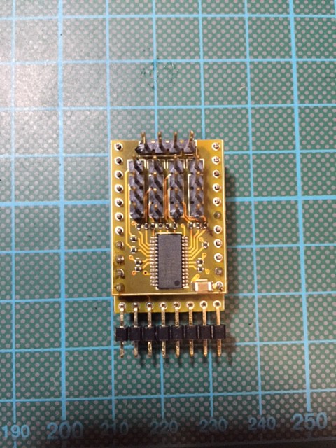
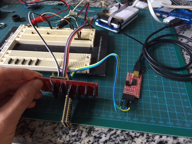
Below is a picture of the submodule connected to a MCU module.
![]()
The headers still need to be trimmed, I know. They will be soon. I'm now going to work on this module's code. As soon as it is working, I'll make it available in the project repository.
Thank you for your help and support. I'd also like to thank Hackaday.io for the help they have given to this project, and to many others, through their great work. I have received a message from them last week saying that the project was one of many awarded with seed money. This was great news for me!
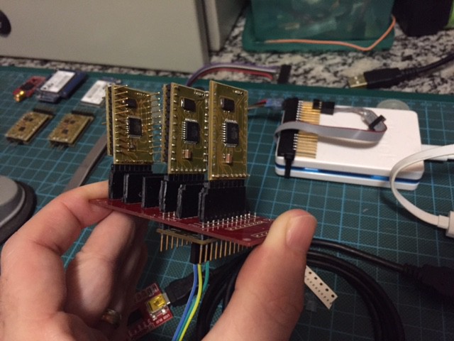
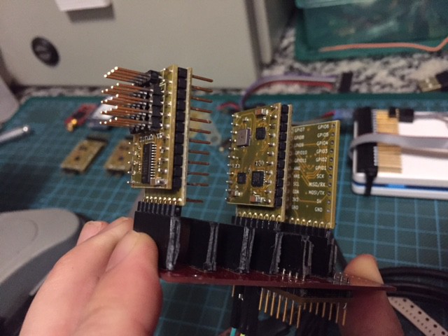
Soon this whole thing will be piloting a tricopter, or a glider, or just a small wheeled robot. Or a flying toilet. Who knows?
![]()
![]()
-
FindChips lists!
04/27/2017 at 18:41 • 0 comments![]()
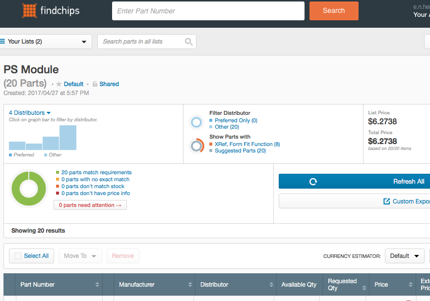
Hi! I'm happy to inform that, due to a nice partnership between Hackaday and FindChips, I can now share the BOMs (bill of materials) of two of the project modules. More lists are coming in the next logs, but the first two ones are here:
MCU module BOM: https://www.findchips.com/u/list/28455-mcu-module
PS module BOM: https://www.findchips.com/u/list/28469-ps-module
Thanks, Hackaday and FindChips for this amazing new feature!
-
New classes. New submodules.
03/10/2017 at 06:08 • 0 commentsHi. I'm working on the flight control module code. I added a few new classes: Navigation, PID, FCM (Flight Control Module), SCM (servo control module), GPS (GPS module) and a very abstract GNC (guidance, navigation and control) class. My main objective is to make GNC the main class for vehicle stabilization. All other vehicle specific attitude control classes should derive from it. Some of the new classes have only the very basic structures needed to integrate them with the system, but FCM inherited code I have already tested against FlightGear in the past, and is able to take a simulated airplane from waypoint a to waypoint b without crashing it.
I regenerated the documentation and uploaded it to labvant.com website. The absence of comments is proportional to the absence of my free time, but doxygen does a great work crossing, formatting and displaying code. Generating documentation with Doxygen was a suggestion from an IRC collaborator: NoHitWonder.
![]()
About the new submodules, a brushless motor control module has already been drafted with the help of Erlend^SE, another project IRC channel collaborator. He is also inspiring and helping with the development of a new power supply module and a ESP8266 module to substitute the RN131G. You can join the project IRC channel by connecting your IRC client to a free node IRC server and joining #labvant.com.
If you like how this project is evolving, please consider supporting it by helping to develop the electronics, the code or the firmware. All the project info is publicly available on the project repo, including schematics, PCB drawings and firmware code in C++. You can also develop your own modules using the project board/connection standards, or propose new standards for future systems. Supporting this project financially by sending a $1 PayPal donation is also welcome. That will help covering the PCB and equipment costs. Thanks a lot for your help and support!
-
Module recognition implemented.
03/04/2017 at 15:31 • 0 commentsToday the module recognition code was successfully debugged. Now it is possible to plug a module on *any* slot of the backbone PCB and it will be recognized by the main communications module. After recognition the module is integrated into the system workflow automatically. If the new module is a sensor one, for example, it is read in sequence with other data source modules, making data available for decision making by the flight control module and further servo positioning.
This is a major step in the system development, giving it a plug-n-play like capability.
![]()
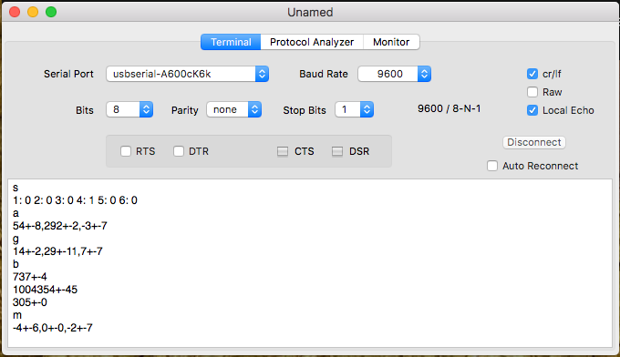
And here is a snapshot of the serial connection to the communications (COM) module. Serial commands are one character long. In the example below, 's' lists the slot occupation, showing the AMGP module (identified by number 1) on slot 4. The other commands return sensor data: a for accelerometer, g for gyroscope, b for barometer (altitude, pressure and temperature) and m for magnetometer. All values are multiplied by 10 or 100, depending on the case, to avoid using floating point numbers. The values shown are averages over a few samples, followed by standard deviation.
The bad news is that the power supplies are failing. I had two buck-boost converters killed by an unknown (to me) factor. I hope to find the mysterious cause when my scope arrives.![]()
If you like how this project is evolving, please consider supporting it by helping to develop the electronics or the firmware. All the project info is publicly available on the project repo, including schematics, PCB drawings and firmware code in C++. You can also develop your own modules using the project board and connection standards, or propose new standards for future systems. Or you can help to support it financially by sending a $1 PayPal donation to help covering the PCB and equipment costs. Thanks a lot for your help and support!
-
Power supplies working!
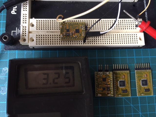
02/19/2017 at 13:48 • 0 commentsBoth power supplies have been tested and seem to be working as expected. I have not tested them with LiPo batteries installed, because those batteries have not arrived yet.
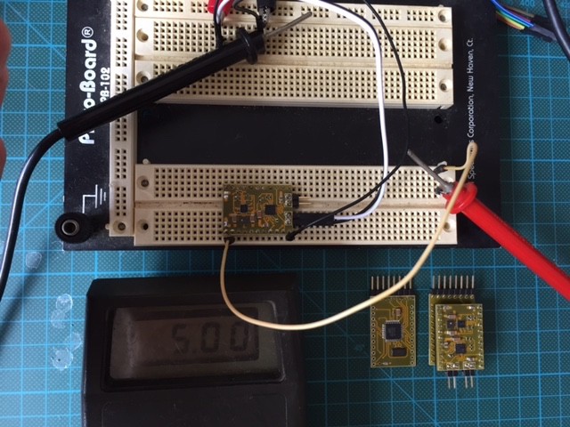
Below are pictures of the 3.3V and the 5V modules. The power supplies are, in theory, capable of sourcing 1.4A at 3.3V and 0.8A at 5V. They can be monitored and controlled by the MCU modules that are attached to them.
![]()
![]()
All the project data, including code, references, datasheets, PCB schematics and design are available as open source and open hardware. You can download everything from the repository and use as you wish. You can even create modules for your own purposes.
If you find this project interesting and believe you can help in some way, please write a message to me (enhering @ gmail . com). Your contribution is very welcome!
-
Power supplies assembled! With LiPo support!
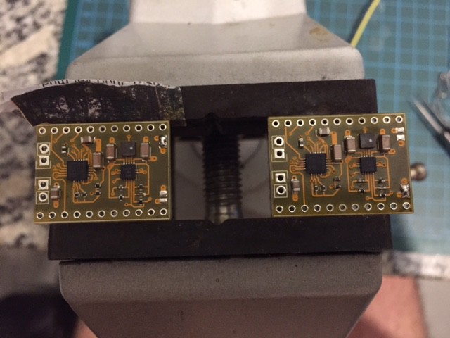
02/13/2017 at 11:14 • 0 commentsHi! I've just finished assembling two power supply submodules, one to run at 3.3V and another at 5V. Each can hold around 1A of current and manage a LiPo cell, charging it automagically or drawing power from it, or from the input line, depending on which options are available at the moment. The 5V power supply will work mostly to feed the servos, while the 3.3V one will feed the logic. These submodules will be attached to a MCU module each. The MCU will monitor and control the power supply, sending and receiving information about available power to the system via the main SPI bus.
![]()
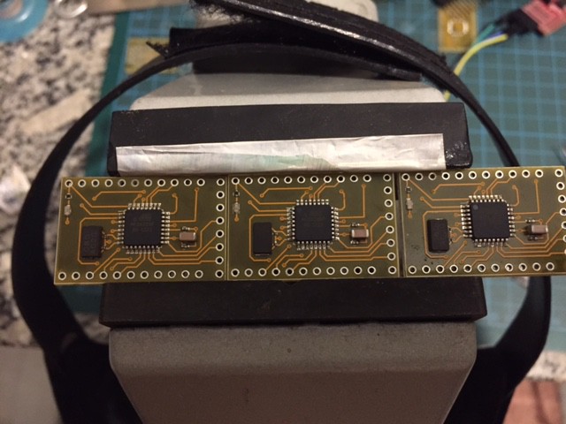
I have also assembled three more MCU modules. Two to drive the power supplies and another to read and process GPS data:
![]()
Soon I'll publish the test results of these modules.
If you like how this project is evolving, please consider supporting it by helping to develop the electronics or the firmware. All the project info is publicly available on the project repo, including schematics, PCB drawings and firmware code in C++. You can also develop your own modules using the project board and connection standards, or propose new standards for future systems. You can also support it financially by sending a $1 PayPal donation to help covering the PCB and equipment costs. Thanks a lot for your help and support!
-
Sensor data via WiFi and serial connection!
02/09/2017 at 04:49 • 0 commentsHi! I have good news!
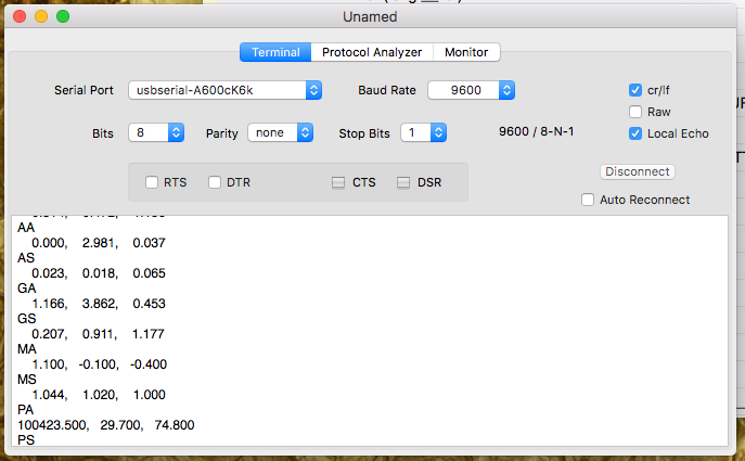
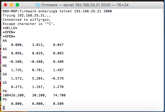
After a long debugging session, today I could read the sensor data via UART and via Wifi. The data was produced in the AMGP sensor module and delivered via SPI to the COM communications module, where it was routed to my computer via UART and via WiFi. This is a major milestone in the system development. I took a screenshot of the serial communications and of the TELNET windows:
![]()
![]()
(AA = Accelerometer averaged data, AS = Accelerometer std dev data, same for magnetometer (M), gyroscope (G) and barometer (P), which delivers pressure, temperature and altitude instead of a three dimensional vector like the other sensors)
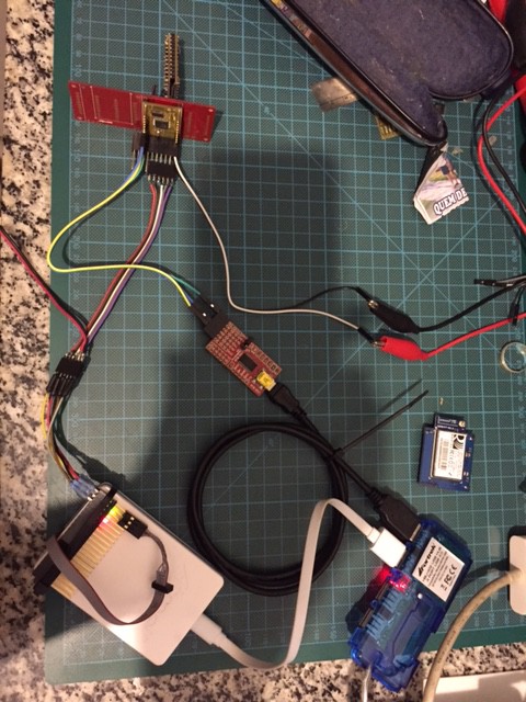
And here is the crazy setup to program and debug the modules:
![]()
I'd like to thank the people from #avr IRC channel on freenode servers for all the help in debugging the code running on the modules, specially carabia, Lambda_aurigae, specing, CapnJ, rue_house and all the others I forgot to mention because my memory does not work well.
I'll be back soon with more good news. Thanks a lot for your support!
-
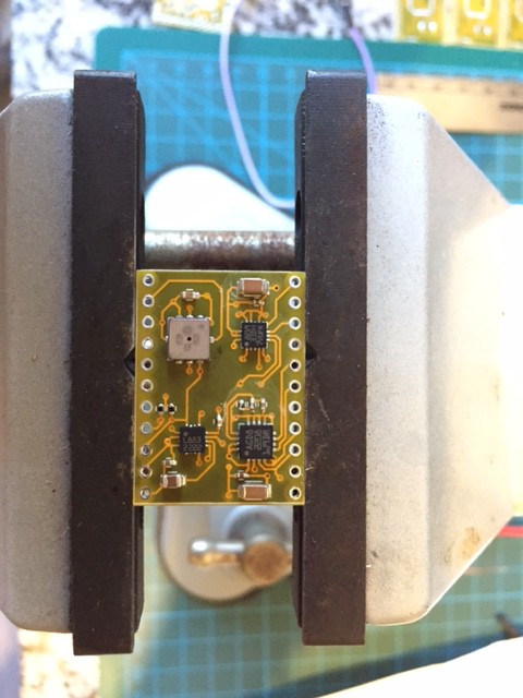
9 dof submodule assembled!
01/20/2017 at 20:09 • 0 comments![]()
![]()
![]()
-
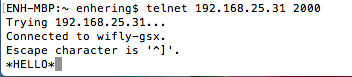
*HELLO* !
01/19/2017 at 03:27 • 2 comments![]()
Hi!
Today the RN131G WiFi module had its firmware successfully upgraded to version 4.41 and I could connect to it via Telnet.
This module is already mounted in his horseshoe PCB breakout and connected to the communications MCU module via the backbone PCB.
This means that now I can connect to the MCU module via WiFi!
My next step is to start to assemble the sensor submodule. Soon I'll publish the sensor readings via WiFi here.
Thank you for your support!
-
First signs of backbone activity
01/17/2017 at 00:01 • 0 comments
Modular Unmanned Vehicle Controller
(former YAUVeC - Yet Another Unmanned Vehicle Controller)