Arcadia Labs
-
Pictures...
07/05/2016 at 13:56 • 0 commentsFirst, I'm very happy to see my little project on Hackaday frontpage today. Thanks Hackaday !
Here are some pictures of the device :
![]() The inside
The inside![]() Cover and buttons
Cover and buttons![]() Device start-up... Hello Jolly Wrencher ! :)
Device start-up... Hello Jolly Wrencher ! :)![]() Test rig using the utility socket : a potentiometer to simulate analog input, and a IR receiver module to simulate digital input.
Test rig using the utility socket : a potentiometer to simulate analog input, and a IR receiver module to simulate digital input.![]() Analog monitor, with min, actual and maximum values, while playing with the potentiometer
Analog monitor, with min, actual and maximum values, while playing with the potentiometer![]() Digital monitor while playing with the IR receiver and a TV remote (sorry for the blur, difficult to capture). Sampling speed could be changed with 10Hz increments. Next feature will be a new running mode, starting only on a pin change, sampling during a fixed time, and then showing on a scrollable / zoomable static graph.
Digital monitor while playing with the IR receiver and a TV remote (sorry for the blur, difficult to capture). Sampling speed could be changed with 10Hz increments. Next feature will be a new running mode, starting only on a pin change, sampling during a fixed time, and then showing on a scrollable / zoomable static graph. -
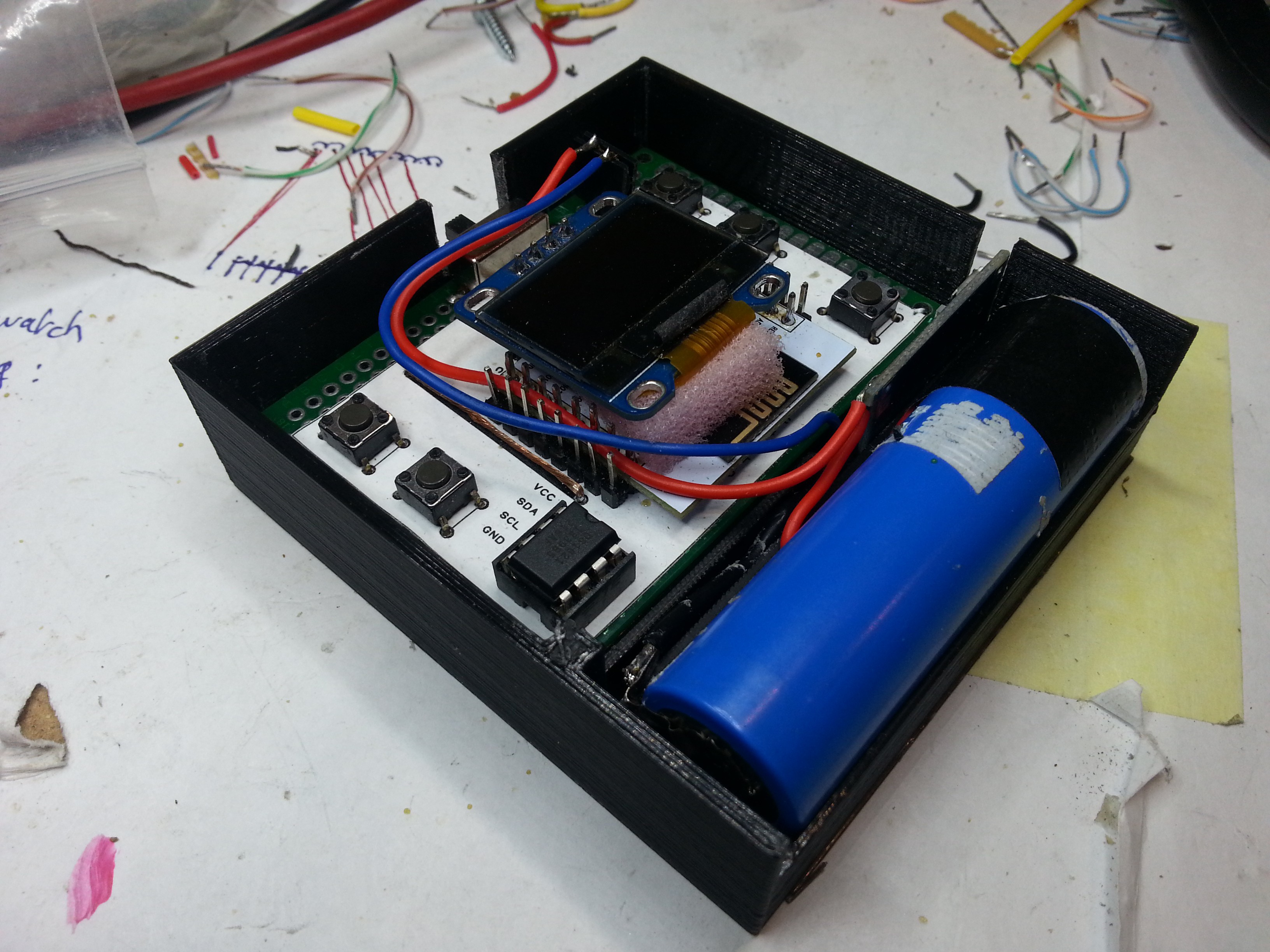
Better enclosure, hardware corrections, software improvements
06/24/2016 at 15:26 • 0 commentsIt's been a few weeks since the last update, but this project is still very active...
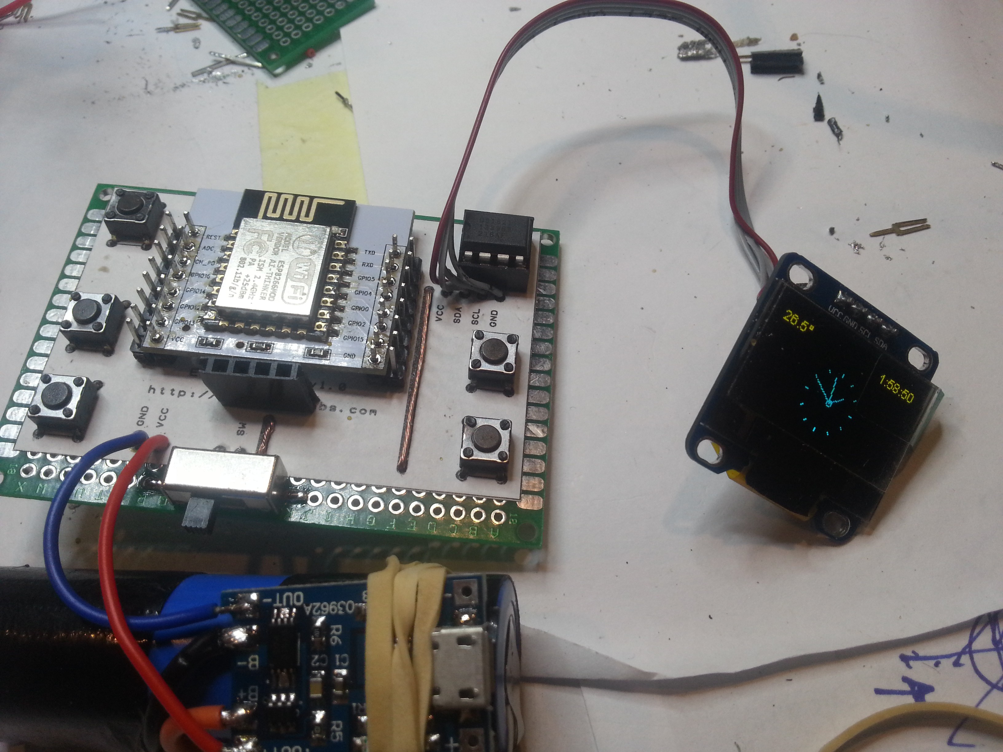
- I wasn't happy with the display positioning, and it looked even worse in the enclosure. So I modified the circuit board, and now the display is "perfectly" centered.
- I discovered too late I couldn't use GPIO2 as an input. Unfortunately, I routed one of the new pushbuttons to this GPIO, so the button was non-functional. I modified the circuit board and routed it to GPIO16 instead (last free GPIO remaining...).
- The first enclosure had a few issues so I re-designed / re-printed it. It is now fitting perfectly.
- I replaced the yellow / blue display with a blue one. I now have 16 pixels more for graphics, charts...
![]()
About the software part :
- The analog monitor is now fully usable (I used it on the field already). It still needs some custom settings
- I wrote the digital monitor, and it is also working very well. Now, I'm trying to find a way to capture / show very fast data (kind of slow signal analyzer). Right now I could sample at 1000Hz reliably, but showing it in a 128x64 graph is not easy...
- I improved the Octoprint 3D printer monitor to better handle connection issues (while roaming)
- I'm actually trying to write the serial monitor code, but this one is giving me headaches...
I'll show pictures and maybe a video in the next build log (paint is still drying).
-
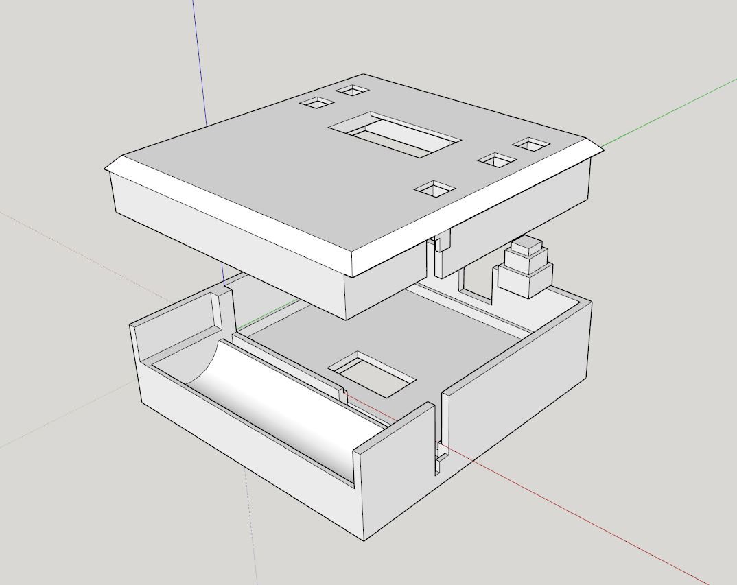
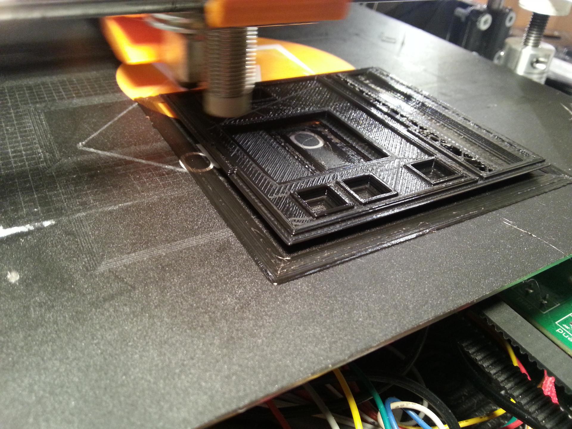
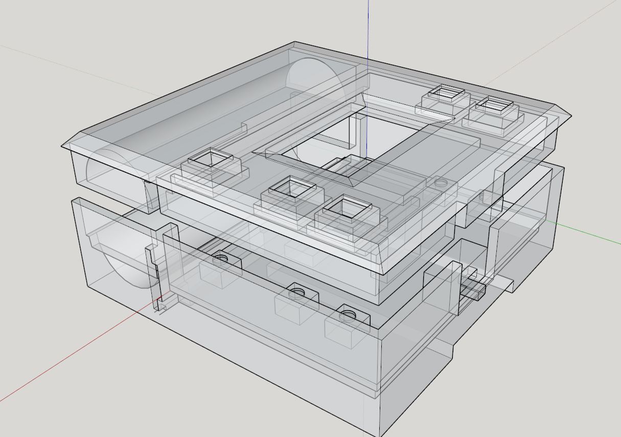
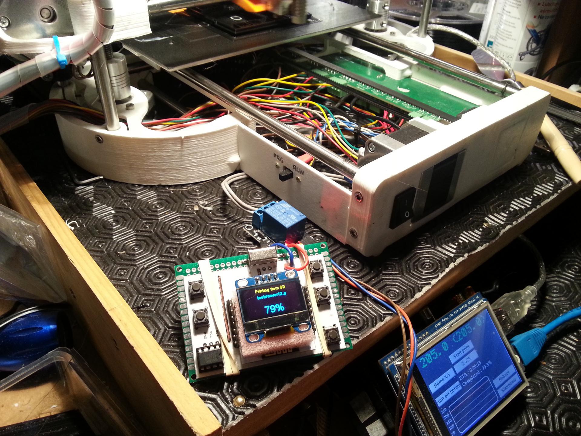
Now, an enclosure
06/11/2016 at 01:35 • 0 commentsI have to do something about it or something bad will happen... 2 months of software and hardware revisions without magic smoke or bug invasion, ... it won't last forever.
I could not play with this device without a proper enclosure anymore...
![]()
![]()
![Printing it's own enclosure.... so untertaining....]()
- left and right buttons are not aligned with oled display : really ? ... :) I'll take care about that while knitting PCB version2.... :)
- forget that, version2 won't be on a perfboard : it will have a real pcb with proper design and charging circuitry...
That being said, the current v1 prototype is very usefull already : today I used it to check my 3d printer while being outside my basement (printing its own enclosure...), and I could use the analog monitor to determine the perfect LDR for a customer device. One month ago, I may have deployed a laptop and an arduino for the same experiment...
3D design is not my thing and I'm not sure if it will work, but it is now printing ... (3D design/printing is just a tool, like PHP, solder iron, electronics design and cake cooking)... as usual, I learned a lot today, goal as been achieved :)
-
First prototype on perfboard
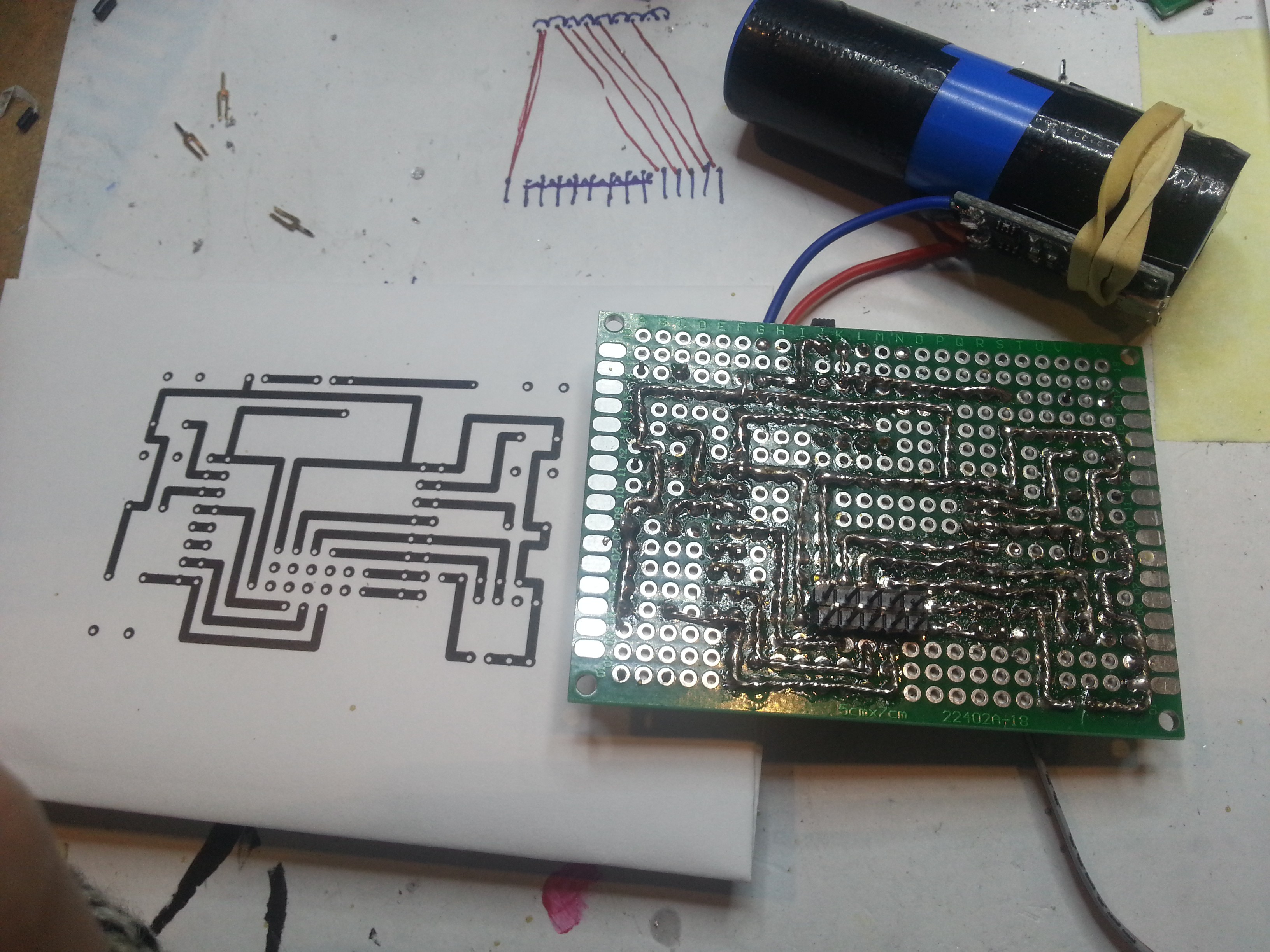
05/30/2016 at 12:21 • 0 commentsI finally built the first prototype circuit on a perfboard.
For those who want the method, here's how I do it :
- first, I draw the layout in Designspark (free PCB software) with 2.54mm spacing everywhere. I try to draw a single layer circuit, with minimal bridges on the top layer.
- when I'm happy with the design, I print both sides on paper (bottom side mirrored). They are my templates.
- I glue the top template on my perfbard, and punch every hole
- I solder the bridges on the top side, and then the components / pin headers
- when it's done, I solder the bottom layer tracks, following my mirrored template.
Here is the result, not too bad for something built on a single rainy day (template PDFs are in the project files).
![]()
![]()
Now, I'm looking for someone to show me how to export a working gerber from Designspark...
-
ESP12 battery experiment
05/26/2016 at 22:28 • 0 commentsOne big problem in my designs is the powering circuit : there are so many dedicated chips, battery chemistries, it's very difficult (for me) to design a good one.
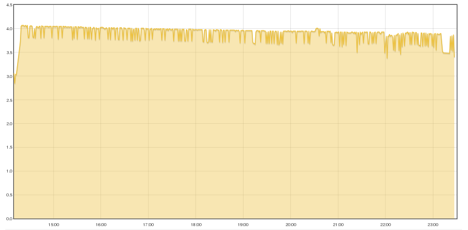
For an experiment, I wanted to know how much time a 2200mAh Li-Ion battery could last with a ESP12, as I plan to use some 18650 cells from dead laptop batteries (I have a lot of these).
So, I bought a TP4056 Li-Ion protecting circuit, and powered the ESP12 directly from the module output, without a regulator. 3.3v<->4.2v is out of specs, I know that, but I successfully powered a bunch of ESP directly from 2.9v to 5v without a problem. So the experiment was almost risk-less.
For the test, I wanted the ESP to eat (drink ?) as much power as possible. So I disabled the screen backlight powersave, overclocked the chip to the max, and made the ESP talking with my 3D printer constantly.
Here is the result. End of the graph is the moment the ESP12 started to show instability (rebooting, not connecting anymore to the AP, etc...)
![]()
So, as a conclusion :
A ESP12 module + SSD1306 OLED could run happily on a Li-Ion battery + protecting circuit during ~9h... This is 245mAh on average.
One could notice the ESP started showing instability around 3.4v, when the datasheet says 3.3v, and I tested it successfully at 2.9v. I think the Li-Ion battery current becomes less stable when depleting. Next experiment will add a very Low Drop Out regulator, actually in the mail...
-
Talking with the 3D printer
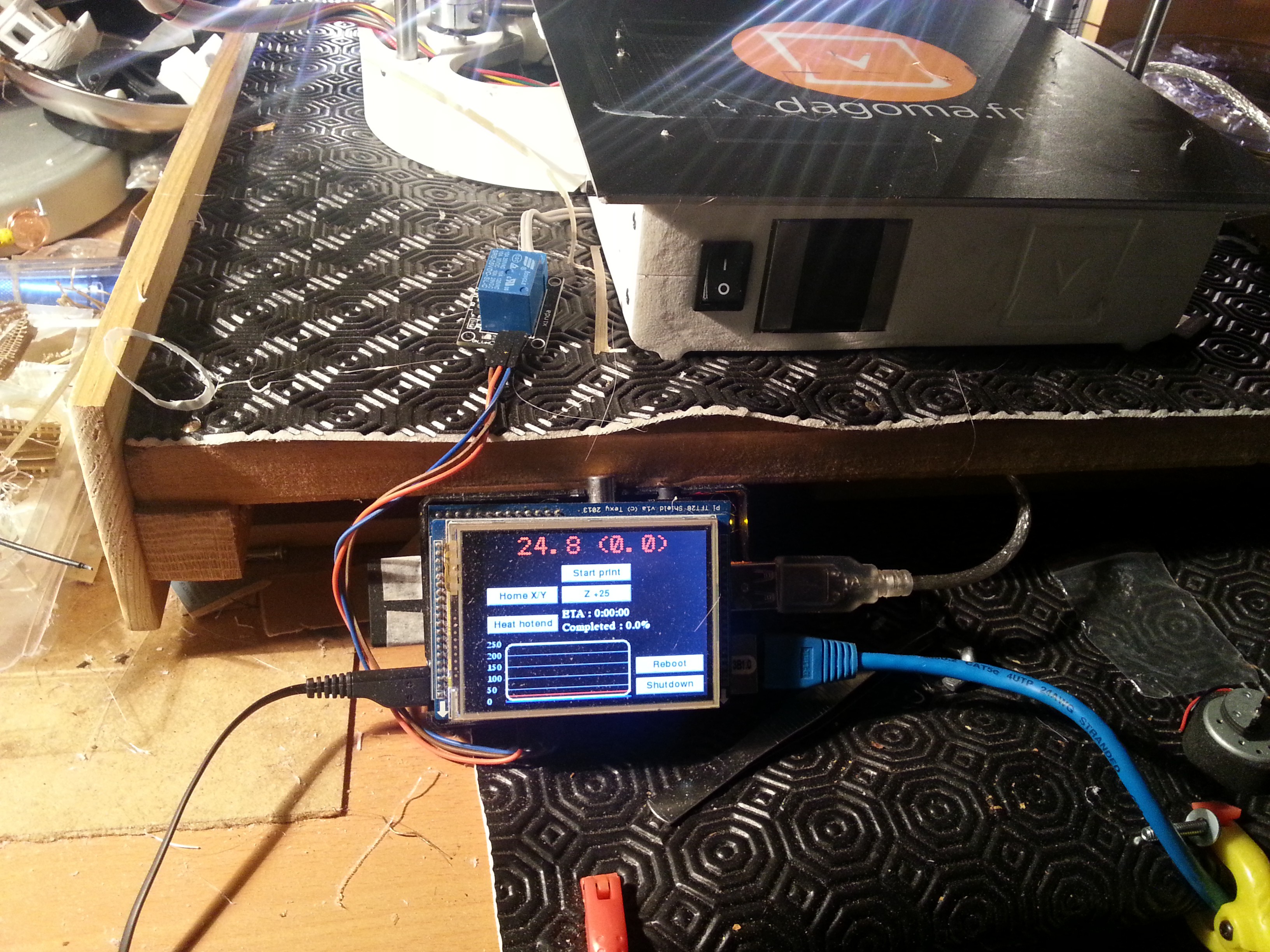
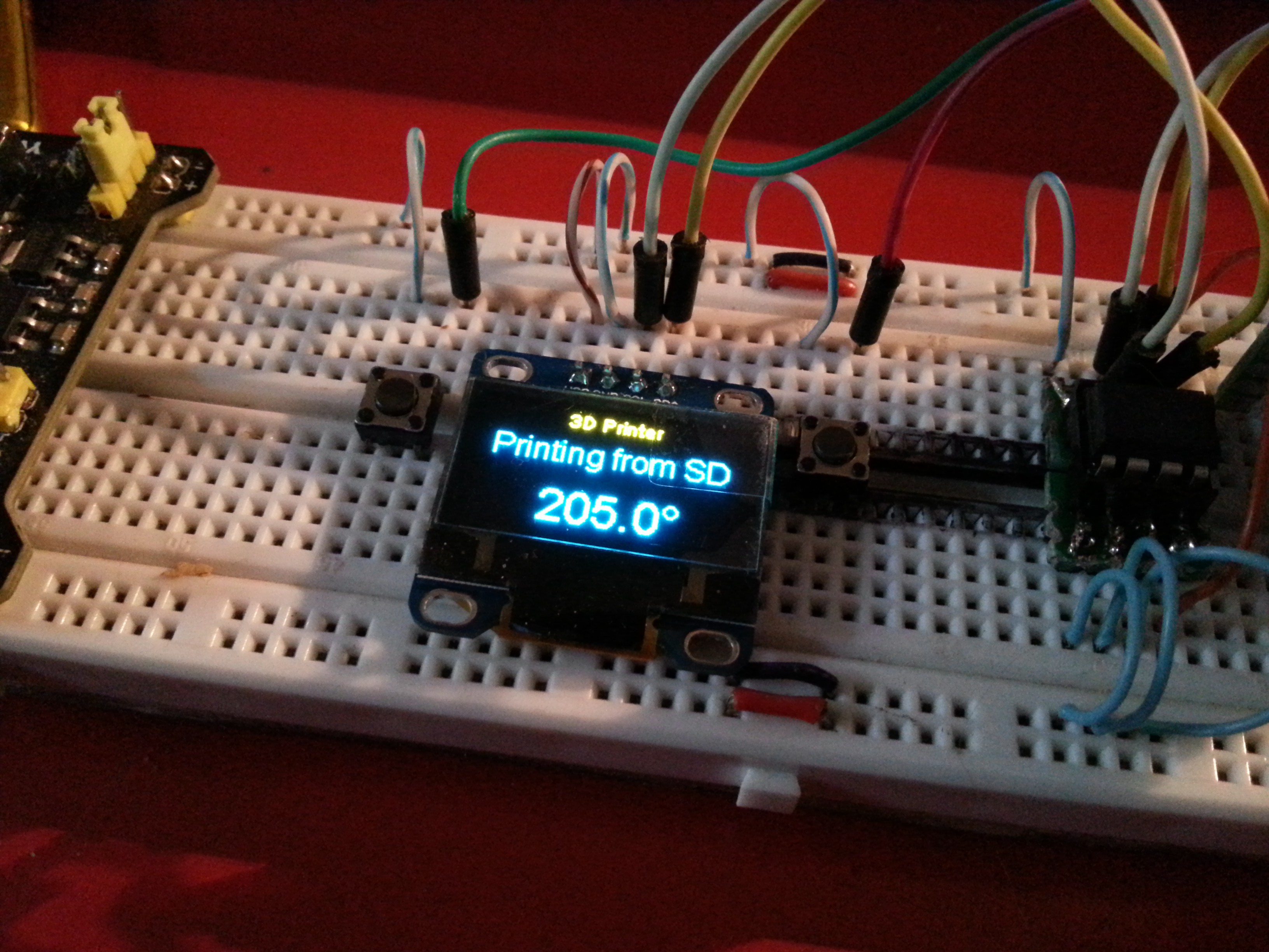
05/26/2016 at 21:57 • 0 commentsThis is the last improvement to the device : showing the state of my 3D printer.
I already connected a Raspberry Pi, a TFT and a relay to the printer, installed Octoprint and writed a custom pygame interface (I love pygame + RPi). It allows me to control it from everywhere.
![]()
I also wanted to check the printer status, without a computer.
Octoprint software exposes an API, so it was almost just a matter of connecting the ESP to it, and parsing the exposed json.
Here is the code :
// OCTOPRINT
#define octoprint_host "1.2.3.4"
const int octoprint_httpPort = 5000;
String octoprint_apikey = "YOUR_OCTOPRINT_API_KEY";

String printerOperational;
String printerPaused;
String printerPrinting;
String printerReady;
String printerText;
String printerHotend;
String printerTarget;

// Function to get and parse the octoprint data
void getOctoPrint() {
  http.begin("http://" + String(octoprint_host) + ":" + String(octoprint_httpPort) + "/api/printer?apikey=" + String(octoprint_apikey) ); //HTTP

  // start connection and send HTTP header
  int httpCode = http.GET();
  // httpCode will be negative on error
  if(httpCode > 0) {
      // HTTP header has been send and Server response header has been handled
      // Serial.println("[OctoPrint] GET... code: " + String(httpCode) );

      if(httpCode == 409) {
        payload = http.getString();
        if (String(payload) == "Printer is not operational") {
          printerText = "Printer is not operational";
        }
      }

      else if(httpCode == 200) {
        payload = http.getString();

        StaticJsonBuffer<1024> jsonBuffer;
        JsonObject& root = jsonBuffer.parseObject(payload.c_str());
        // Test if parsing succeeds.
        if (!root.success()) {
          Serial.println("parseObject() failed");
          return;
        }
        else {
          const char* text;
          text = root["state"]["text"];
          printerText = String(text);
          text = root["state"]["flags"]["operational"];
          printerOperational = String(text);
          text = root["state"]["flags"]["paused"];
          printerPaused = String(text);
          text = root["state"]["flags"]["printing"];
          printerPrinting = String(text);
          text = root["state"]["flags"]["ready"];
          printerReady = String(text);
          text = root["temperature"]["tool0"]["actual"];
          printerHotend = String(text);
          text = root["temperature"]["tool0"]["target"];
          printerTarget = String(text);

          return;
        }
      }
      else {
        payload = http.getString();
        Serial.println( "[OctoPrint] HTTP_CODE_" + String(httpCode) + " : " + String(payload) );
      }
  } else {
      Serial.println("[OctoPrint] GET... failed, error: " + String(http.errorToString(httpCode).c_str()) );
  }
  http.end();
}

// Function to show octoprint state to the display
void octoprint1(SSD1306 *display, SSD1306UiState* state, int16_t x, int16_t y) {
  page = 41;
  ui.disableIndicator();
  if (printerText == "Printer is not operational") {
    display->setTextAlignment(TEXT_ALIGN_CENTER);
    display->setFont(ArialMT_Plain_16);
    display->drawString(displayWidth / 2 + x , 14 + y, "OFF" );
  }
  else {
    display->setTextAlignment(TEXT_ALIGN_CENTER);
    display->setFont(ArialMT_Plain_16);
    display->drawString(displayWidth / 2 + x , 14 + y, printerText);
    display->setFont(ArialMT_Plain_24);
    display->drawString(displayWidth / 2 + x , 40 + y, printerHotend + "°");
  }

}
Of course, you will have to check the octoprint status on timed intervals (I set it to 5 seconds).It is also a very basic script, using the "state" json only. An improved script, checking the other exposed json, could tell remaining printing time, % completed, file being printed, etc... (example : http://docs.octoprint.org/en/master/api/job.html)
![]()
In all honesty : this is very cool and I love this feature !
-
The Utility Socket explained
05/25/2016 at 21:07 • 0 commentsIn the details, I mentioned the "utility socket" I plan to add to the device.
I'm trying to use only I2C modules and components inside the device. So, there are "a lot" of unused GPIOs.
I plan to use some of these remaining GPIOs in the utility socket :
- 3.3v
- GND
- UART Tx
- UART Rx
- I2C SDA
- I2C SCL
- ADC
- 1 digital pin
- GPIO 0
- Reset
It would allow using "slave modules" with the device, while GPIO 0 and Reset will allow to reprogram it.
For an example, I could plug a I2C Inertial Measurement Unit, or a Serial GPS.
I plan to also use AtTinys and Atmegas coupled with sensors/actuators, as I2C slave devices. This way, I could use some IO absent on the ESP8266 : SPI, hardware PWM, analog... Each slave device will have its own unique address, so the main device could identify it, and run the appropriate function.
-
Sending data to emonCMS server
05/25/2016 at 19:57 • 0 commentsThe device sends its voltage and temperature to my emoncms server.
Emoncms (https://openenergymonitor.org/emon/) is an open-source web-based software for monitoring home power, temperature and sensors. This is a central part of my DIY home automation system.
Emoncms exposes an API, so reading / posting data to the server is very easy.
Here is the piece of code I'm using :
#define emoncms_host "1.2.3.4"
const int emoncms_httpPort = 80;
String emoncms_apikey = "YOUR_API_KEY";
int node = 1;

void postEmoncms() {
  // run only if the ESP is connected to a network
  if ( WiFi.status() == WL_CONNECTED ) {
    WiFiClient client;
    if (!client.connect(emoncms_host, emoncms_httpPort)) {
      Serial.println("Post to emoncms failed");
      return;
    }
    // We now create a URI for the request
    String url = "GET /emoncms/input/post.json?apikey=" + emoncms_apikey + "&node=" + node + "&json={2:" + temperature + ",1:" + vcc + "";
    client.println(url);
    client.print("Host: ");
    client.println(emoncms_host);
    client.println("Connection: close");
    client.println();
    client.stop(); //Stopping client
    Serial.println("Post to emoncms : success");
  }
  else {
    Serial.println("Post to emoncms : not connected to internet");
  }
}
Of course, this function shouldn't run constantly in the main loop, but should run on timed intervals. I'm using RBD_Timer lib (https://github.com/alextaujenis/RBD_Timer)This function runs in the background, so there won't be any screenshot this time !
-
Getting time...
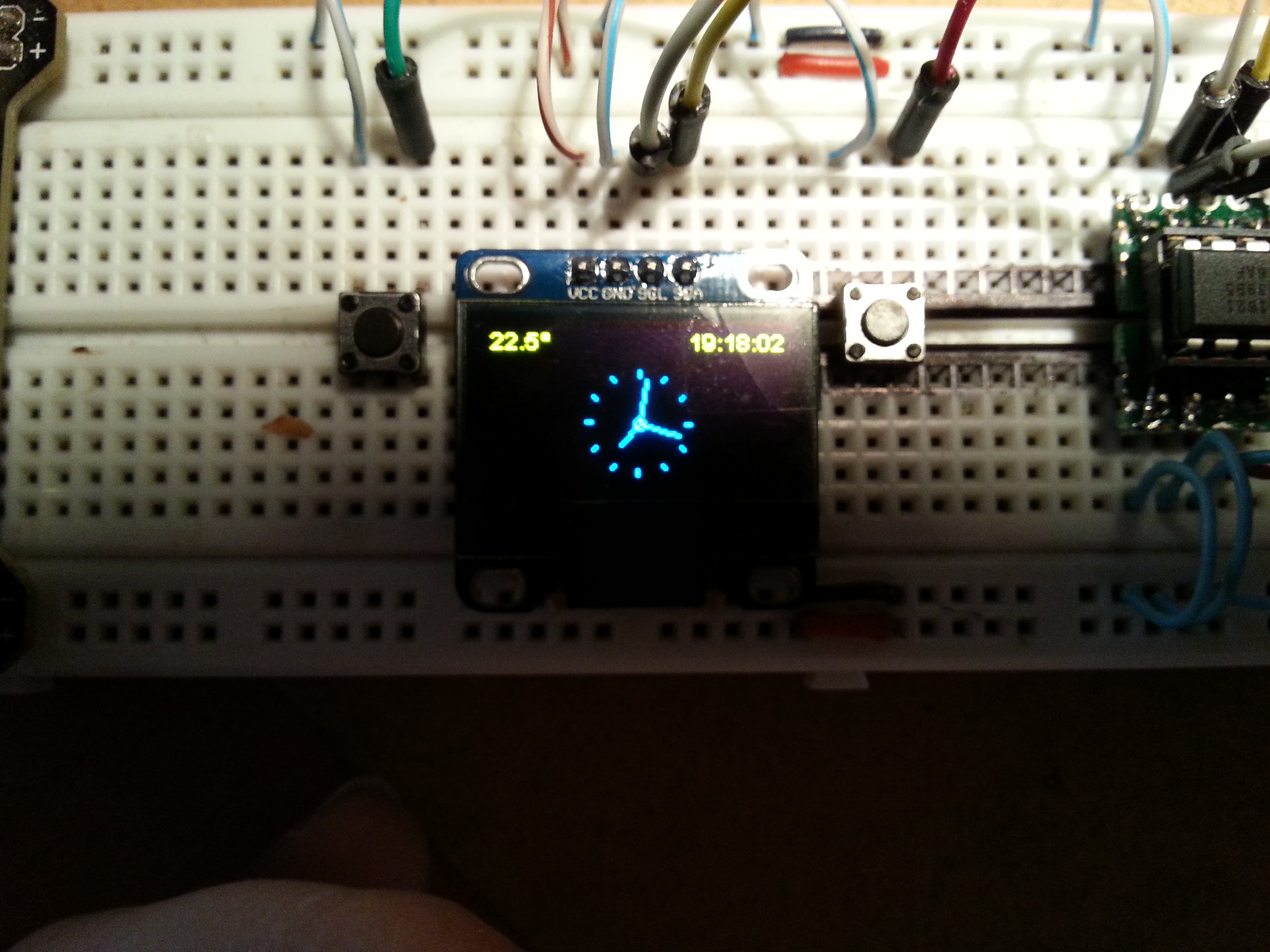
05/24/2016 at 23:45 • 0 commentsWith a working menus system, the first thing to add is a clock.
![]()
If possible, I don't want to add a RTC chip, so I have to find a way to get time.
Fortunately, we have NTP / Network Time Protocol. So I only need a working internet connectivity to set time.
Here is the piece of code to do just that :
unsigned int localPort = 2390;      // local port to listen for UDP packets

/* Don't hardwire the IP address or we won't get the benefits of the pool.
 *  Lookup the IP address for the host name instead */
// IPAddress timeServer(129, 6, 15, 28); // time.nist.gov NTP server
IPAddress timeServerIP; // time.nist.gov NTP server address

const int NTP_PACKET_SIZE = 48; // NTP time stamp is in the first 48 bytes of the message

byte packetBuffer[ NTP_PACKET_SIZE]; //buffer to hold incoming and outgoing packets

// A UDP instance to let us send and receive packets over UDP
WiFiUDP udp;

unsigned long sendNTPpacket(IPAddress& address)
{
  Serial.println("sending NTP packet...");
  // set all bytes in the buffer to 0
  memset(packetBuffer, 0, NTP_PACKET_SIZE);
  // Initialize values needed to form NTP request
  // (see URL above for details on the packets)
  packetBuffer[0] = 0b11100011;   // LI, Version, Mode
  packetBuffer[1] = 0;     // Stratum, or type of clock
  packetBuffer[2] = 6;     // Polling Interval
  packetBuffer[3] = 0xEC;  // Peer Clock Precision
  // 8 bytes of zero for Root Delay & Root Dispersion
  packetBuffer[12]  = 49;
  packetBuffer[13]  = 0x4E;
  packetBuffer[14]  = 49;
  packetBuffer[15]  = 52;

  // all NTP fields have been given values, now
  // you can send a packet requesting a timestamp:
  udp.beginPacket(address, 123); //NTP requests are to port 123
  udp.write(packetBuffer, NTP_PACKET_SIZE);
  udp.endPacket();
}

void get_NTP() {
  Serial.print("Starting UDP\n");
  udp.begin(localPort);
  Serial.print("Local port: ");
  Serial.println(udp.localPort());

  //get a random server from the pool
  WiFi.hostByName(ntpServerName, timeServerIP);

  sendNTPpacket(timeServerIP); // send an NTP packet to a time server
  // wait to see if a reply is available
  delay(1000);

  int cb = udp.parsePacket();
  if (!cb) {
    Serial.print(".");
  }
  else {
    Serial.println("");
    Serial.print("packet received, length=");
    Serial.println(cb);
    // We've received a packet, read the data from it
    udp.read(packetBuffer, NTP_PACKET_SIZE); // read the packet into the buffer

    //the timestamp starts at byte 40 of the received packet and is four bytes,
    // or two words, long. First, esxtract the two words:

    unsigned long highWord = word(packetBuffer[40], packetBuffer[41]);
    unsigned long lowWord = word(packetBuffer[42], packetBuffer[43]);
    // combine the four bytes (two words) into a long integer
    // this is NTP time (seconds since Jan 1 1900):
    unsigned long secsSince1900 = highWord << 16 | lowWord;
    Serial.print("Seconds since 1 1 1900 = " );
    Serial.println(secsSince1900);

    // now convert NTP time into everyday time:
    Serial.print("Unix time = ");
    // Unix time starts on Jan 1 1970. In seconds, that's 2208988800:
    const unsigned long seventyYears = 2208988800UL;
    // subtract seventy years:
    unsigned long epoch = secsSince1900 - seventyYears + timeZone * SECS_PER_HOUR;
    // print Unix time:
    Serial.println(epoch);
    setTime(epoch);
  }
}

get_NTP()
Conversion from epoch to human time is easily done with the TimeLib library. For an example :String timeNow = String(hour()) + ":" + String(minute()) + ":" + String(second());Finally, here is the piece of code I'm using to display the analog clock :
int screenW = 128;
int screenH = 64;
int clockCenterX = screenW/2;
int clockCenterY = ((screenH-16)/2)+16;   // top yellow part is 16 px height
int clockRadius = 23;

void analogClockFrame(SSD1306 *display, SSD1306UiState* state, int16_t x, int16_t y) {
  ui.disableIndicator();

  // Draw the clock face
  //  display->drawCircle(clockCenterX + x, clockCenterY + y, clockRadius);
  display->drawCircle(clockCenterX + x, clockCenterY + y, 2);
  //
  //hour ticks
  for( int z=0; z < 360;z= z + 30 ){
  //Begin at 0° and stop at 360°
    float angle = z ;
    angle = ( angle / 57.29577951 ) ; //Convert degrees to radians
    int x2 = ( clockCenterX + ( sin(angle) * clockRadius ) );
    int y2 = ( clockCenterY - ( cos(angle) * clockRadius ) );
    int x3 = ( clockCenterX + ( sin(angle) * ( clockRadius - ( clockRadius / 8 ) ) ) );
    int y3 = ( clockCenterY - ( cos(angle) * ( clockRadius - ( clockRadius / 8 ) ) ) );
    display->drawLine( x2 + x , y2 + y , x3 + x , y3 + y);
  }

  // display second hand
  float angle = second() * 6 ;
  angle = ( angle / 57.29577951 ) ; //Convert degrees to radians
  int x3 = ( clockCenterX + ( sin(angle) * ( clockRadius - ( clockRadius / 5 ) ) ) );
  int y3 = ( clockCenterY - ( cos(angle) * ( clockRadius - ( clockRadius / 5 ) ) ) );
  display->drawLine( clockCenterX + x , clockCenterY + y , x3 + x , y3 + y);
  //
  // display minute hand
  angle = minute() * 6 ;
  angle = ( angle / 57.29577951 ) ; //Convert degrees to radians
  x3 = ( clockCenterX + ( sin(angle) * ( clockRadius - ( clockRadius / 4 ) ) ) );
  y3 = ( clockCenterY - ( cos(angle) * ( clockRadius - ( clockRadius / 4 ) ) ) );
  display->drawLine( clockCenterX + x , clockCenterY + y , x3 + x , y3 + y);
  //
  // display hour hand
  angle = hour() * 30 + int( ( minute() / 12 ) * 6 )   ;
  angle = ( angle / 57.29577951 ) ; //Convert degrees to radians
  x3 = ( clockCenterX + ( sin(angle) * ( clockRadius - ( clockRadius / 2 ) ) ) );
  y3 = ( clockCenterY - ( cos(angle) * ( clockRadius - ( clockRadius / 2 ) ) ) );
  display->drawLine( clockCenterX + x , clockCenterY + y , x3 + x , y3 + y);
}
Disclaimer : this is part of the clock demo I added to the SSD1306 lib, here : https://github.com/CaptainStouf/esp8266-oled-ssd1306/blob/dev-branch-3.0.0/examples/SSD1306ClockDemo/SSD1306ClockDemo.ino -
Choosing a SSD1306 lib
05/24/2016 at 23:13 • 0 commentsI have to find a SSD1306 compatible with ESP8266. I need it to be simple and fast.
Fortunately, I found https://github.com/squix78/esp8266-oled-ssd1306.
It is easy to use, easy to hack, with very nice UI functions : it works like a scrolling carousel, and I could use this feature and 2 pushbuttons to navigate in menus.
It also has a overlay feature, very handy to draw some kind of "status bar".
Here is an example :
The lib is so good I forked it and I'm now contributing to the dev branch (https://github.com/CaptainStouf/esp8266-oled-ssd1306/tree/dev-branch-3.0.0). I added the drawLine function and a quick/dirty hack for multilevel menus (I will soon improve that).![]()
ESP Swiss Knife
This battery powered device is a all-in-one toolbox : WiFi AP, 3D printer remote, clock, serial console, sensors hub, and many more...
 The inside
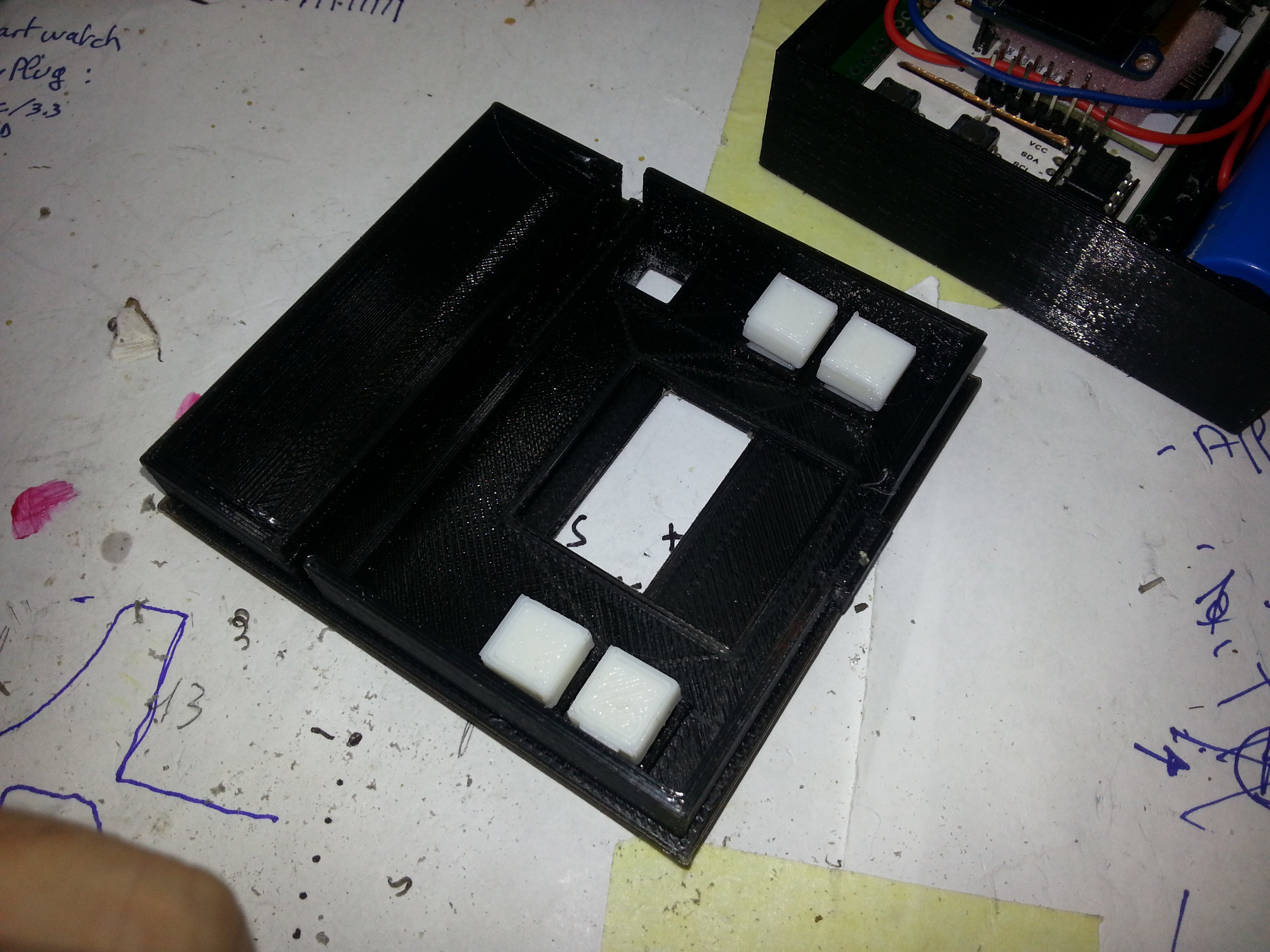 Cover and buttons
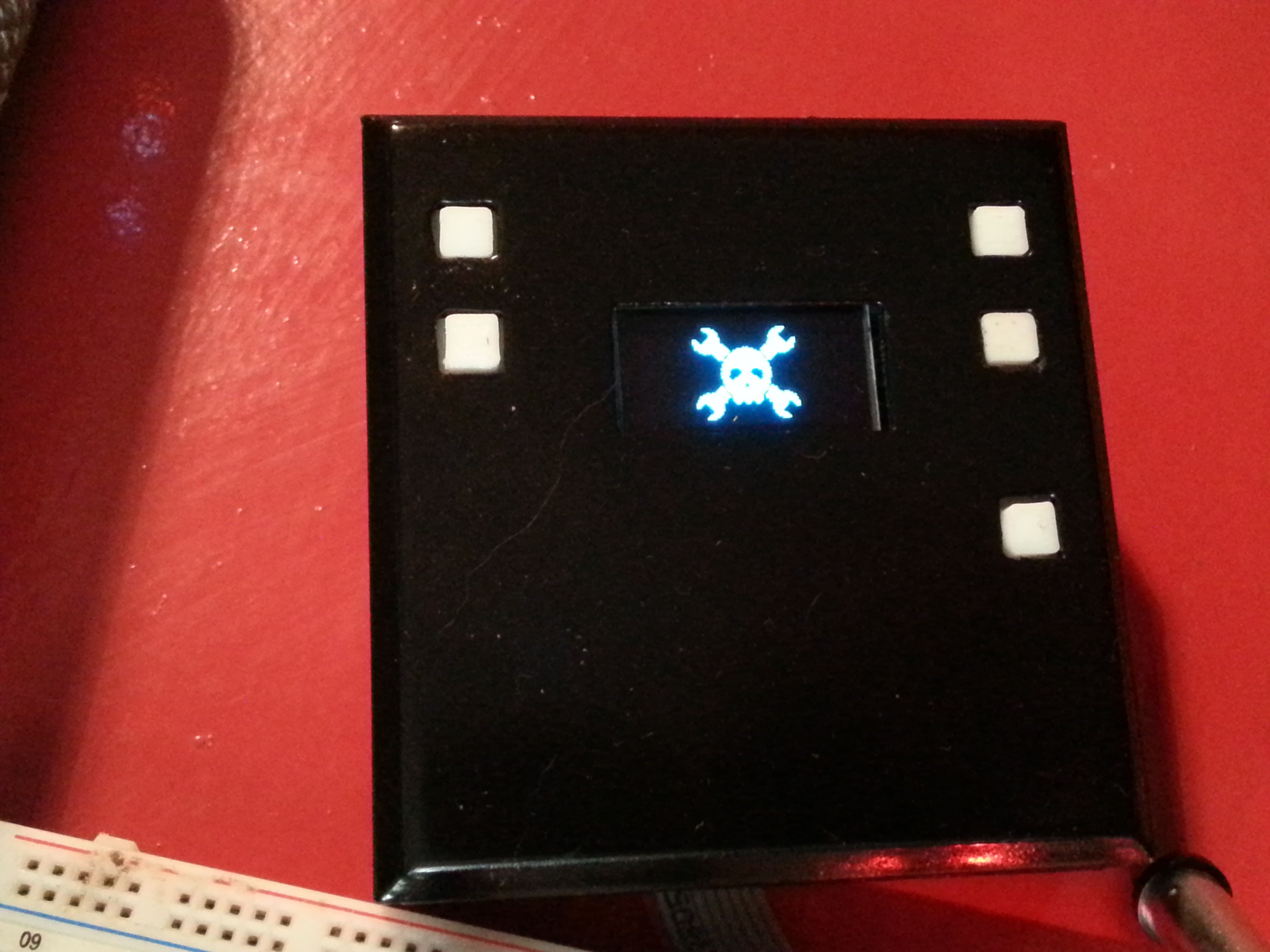 Device start-up... Hello Jolly Wrencher ! :)
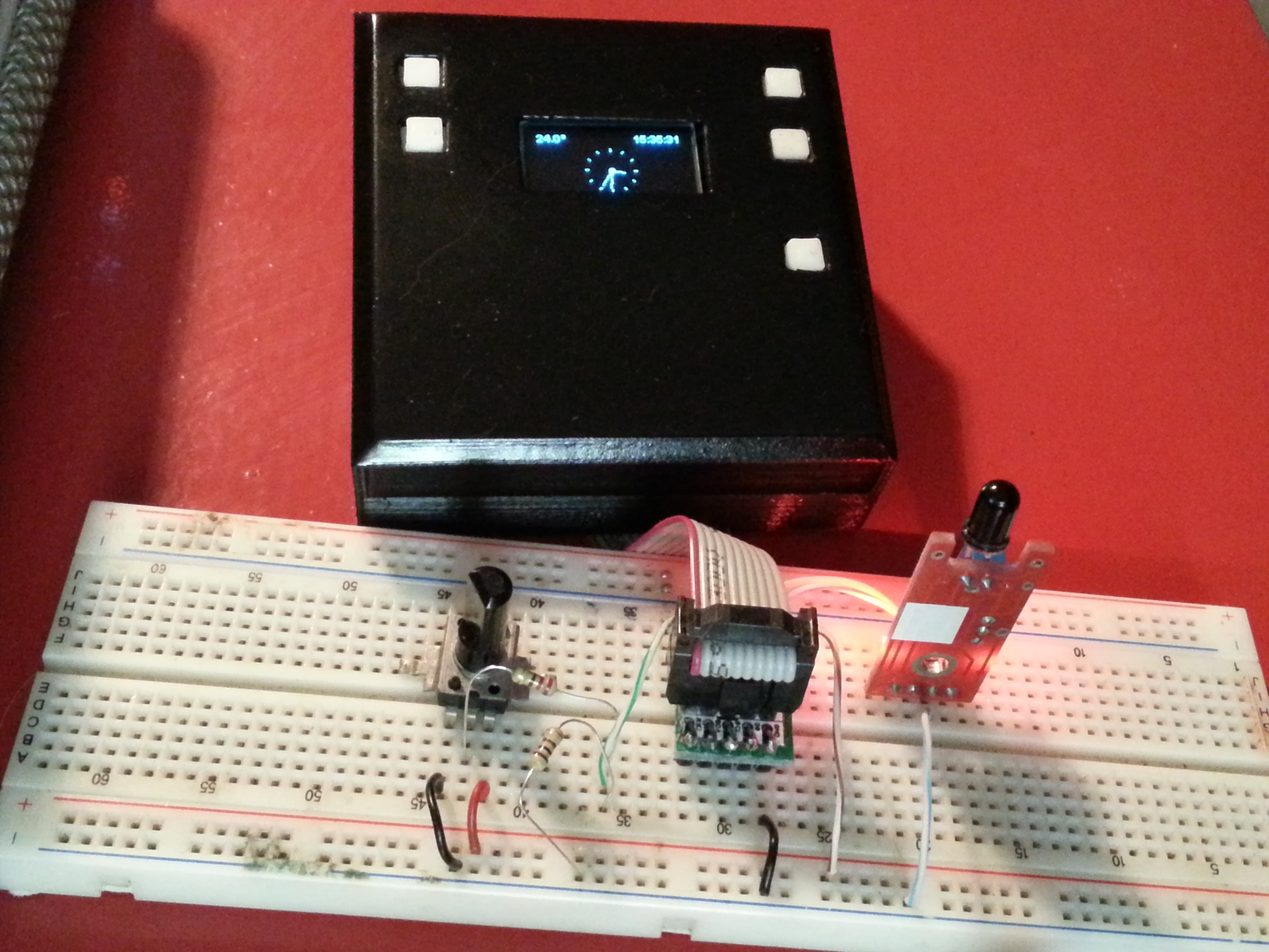 Test rig using the utility socket : a potentiometer to simulate analog input, and a IR receiver module to simulate digital input.
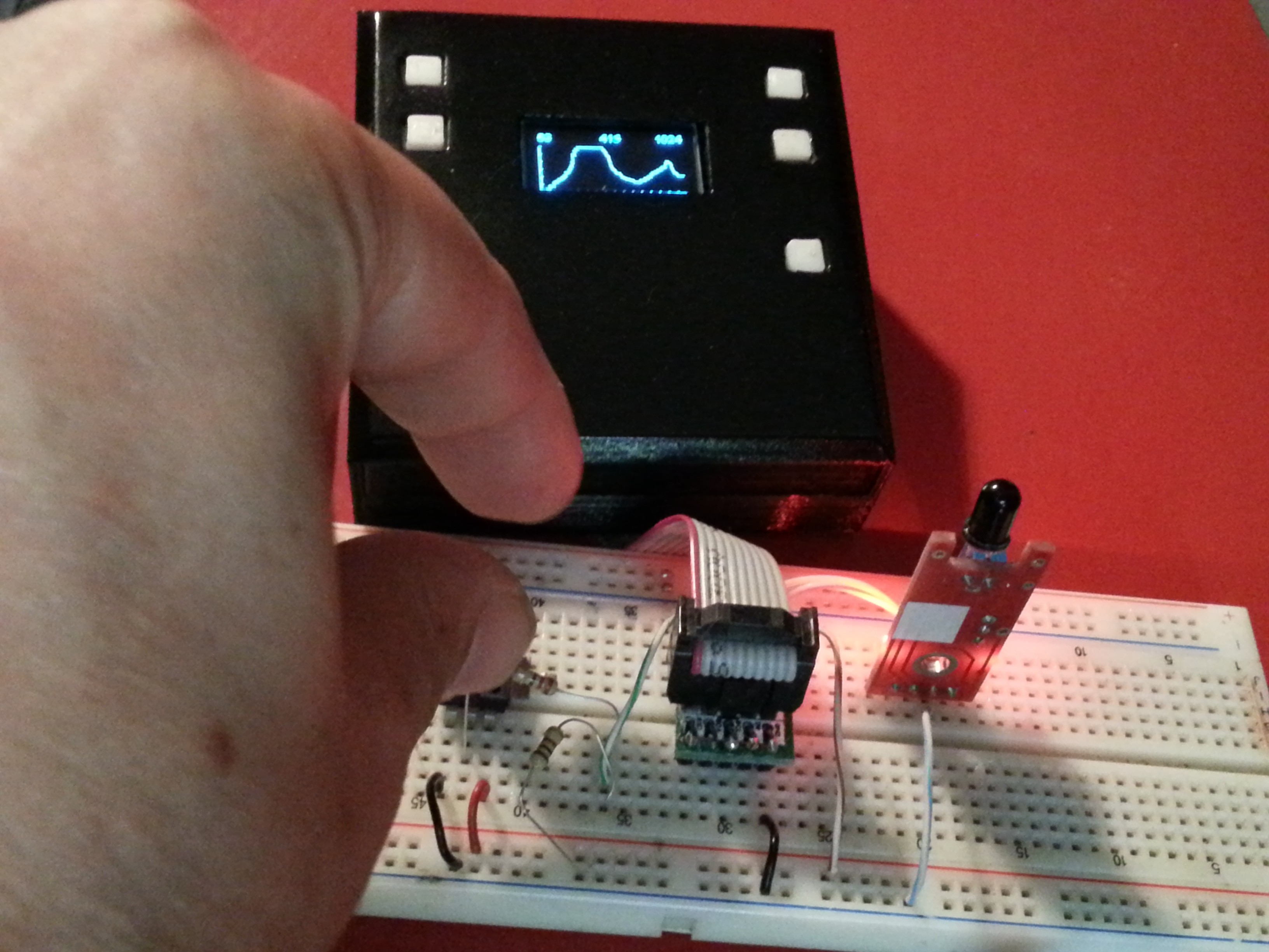 Analog monitor, with min, actual and maximum values, while playing with the potentiometer
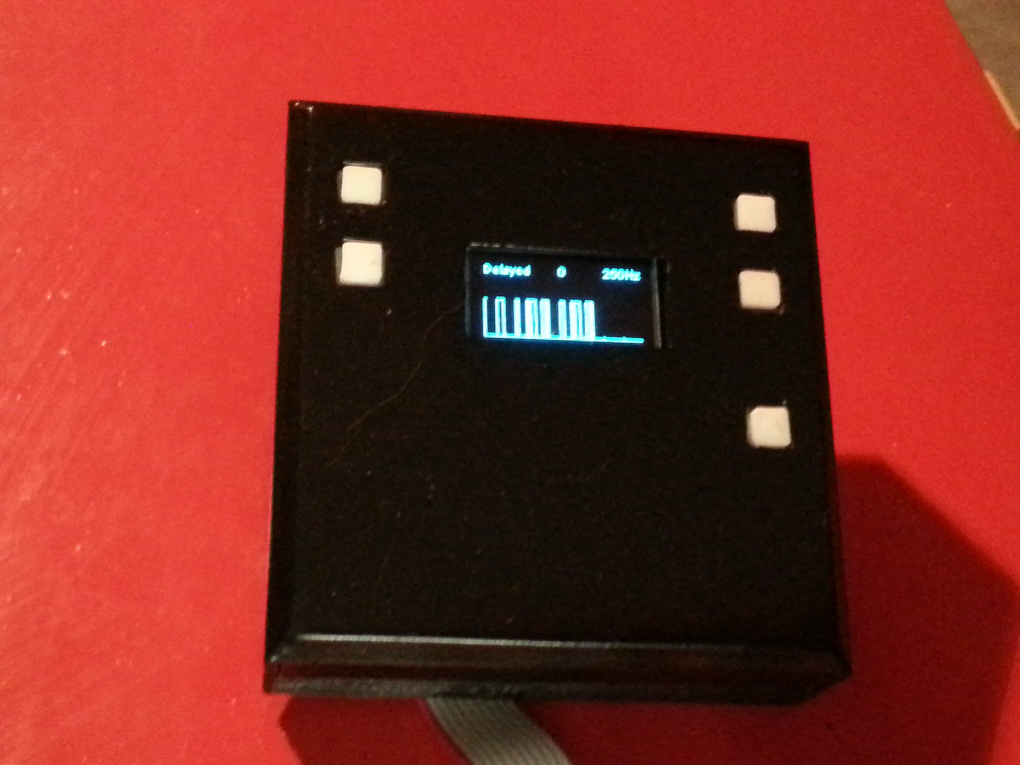 Digital monitor while playing with the IR receiver and a TV remote (sorry for the blur, difficult to capture). Sampling speed could be changed with 10Hz increments. Next feature will be a new running mode, starting only on a pin change, sampling during a fixed time, and then showing on a scrollable / zoomable static graph.