will.stevens
-
Relay evolution
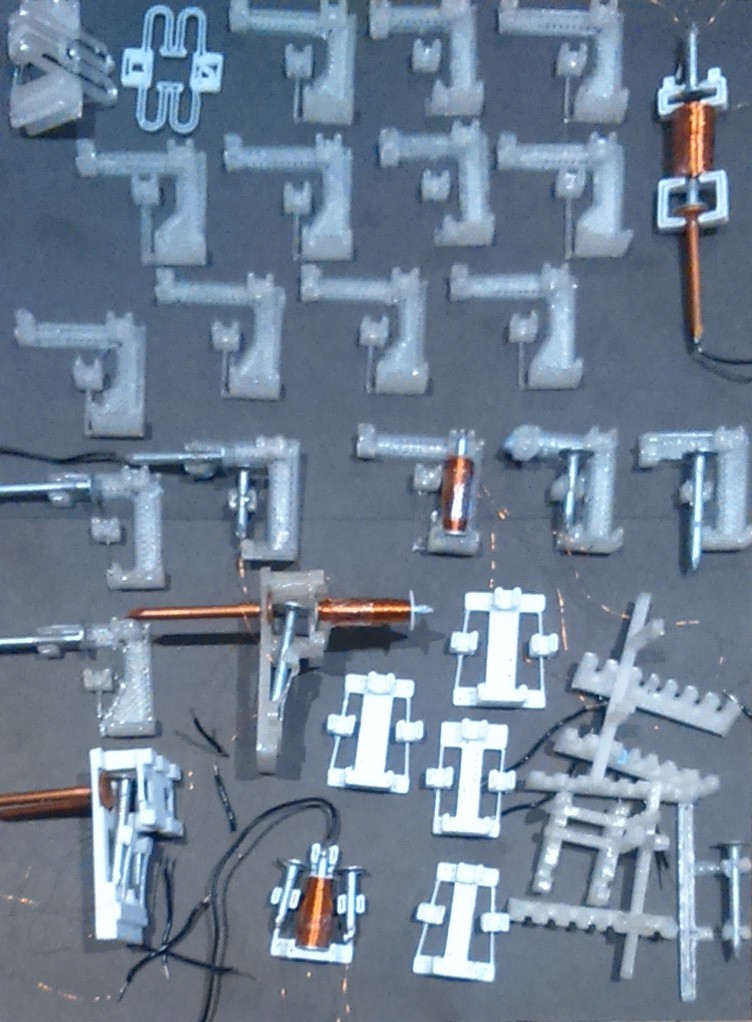
08/21/2016 at 20:15 • 0 commentsI sorted through old 3D printed parts today, deciding what to keep and what to discard. I was able to do some archaeology on several generations of relays:
![]()
Early designs (bottom right) were based on snap-together frames so that different ideas could be tried and and altered quickly. This proved too flimsy and these relays typically failed mechanically after a few hundred operations unless glued together. Some designs (top right, top left and bottom left) were one-offs and not good enough to displace already successful designs (but with further work they might be viable). Successful designs tend to lead to multiple versions with variations in the structures that give the relay its characteristics.
-
A pegboard memory
08/21/2016 at 19:59 • 0 commentsA few months ago I made a prototype punched card reader. It worked by pressing nails against the card as it was fed through the device. When holes in the card passed under the nails, the nails made contact with other nails on the other side of the card. A video of it can be found here.
There are several problems with it that might be fixable after a few prototyping iterations: the nails were at too steep an angle, the nails tended to pop out and needed to be held in with a rubber band, part of the frame had to be resized with a knife because the cogs kept getting caught, the flexible tines that held the nails in place were under constant strain and deformed over time.
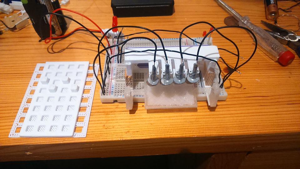
An alternative card reading mechanism occurred to me, based on a pegboard with movable pegs. Movable pegs make it possible to reprogram the card without having to print or punch another one.
The photos below show a prototype. It is made using glued together parts of the earlier punched card reading prototype - this iteration is aimed at getting the dimensions right before printing out a new version.![]()
![]()
This video shows the operation of a single sensing tine:
This video shows all four tines in place, successfully reading the state of the pegs as they pass through: -
An SPST relay
08/20/2016 at 22:59 • 0 commentsI've been working on a single-pole single-throw (SPST) relay, after realising that all of the circuits that I am interested in and have been prototyping with SPDT relays can be made equally well using SPST relays (albeit using a few more than if SPDT relays are used).
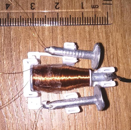
Here's a photo of the relay:![]()
The design constraints on relays mean that it is easier to make a good SPST relay than an SPDT relay. In an SPDT relay, the spring keeping the normally closed (NC) contact closed must exert enough force so that the NC contact resistance is low. But the larger this force, the greater the power required to operate the relay and make a low resistance contact at the normally open (NO) contact. Also, since I'm using PLA, the spring holding the NC contact closed tends to creep over time, even when the relay is not in use, causing the NC contact resistance to reduce.
Here is a video of the relay being tested:
You can see that there are two pole nails, both of which close on a common NO nail. The idea behind having two pole nails is that they should be wired in parallel to reduce the chance of getting a bad contact closure (due to dust or some other problem) - only if there is a bad closure on both contacts will the relay fail. I believe that a similar idea is employed in some commercial miniature relays.
An initial manual scroll through the test data shows that the relay operated correctly for about 3000 cycles (i.e. until the test ended), with a load of 50 ohms. The contact resistance when both contacts are wired in parallel is about 0.5 ohms at the beginning of the test, and slowly increases to about 1.5 ohms by the end of the test. I don't know whether the increase in resistance is due to a mechanical change in the relay over the course of the test, or a change to the surfaces of the contacts.
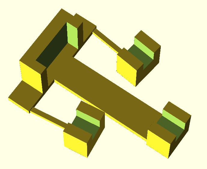
Here is an image of the 3D printed part of the relay:![]()
The OpenSCAD files for this relay are available in github: relay7c.scad
The coil is 2150 turns of 40 swg enameled copper wire wound around a 30mm long galvanized iron nail. The pole nails are 20mm long. All nails have a 3mm diameter shaft. The coil is tapered slightly and is only wound around 19mm of the nail, to allow space for the pole nails to make contact. The coil is held in place by a small 3D printed washer. The resistance of the coil is 57 ohms.
There are still a couple of problems with this relay:- It's difficult to make relays with a consistently sized gap between the pole nail heads and the coil nail.
- Because there is no NC contact, the pole nails are not very well damped, and after the relay is deactivated they tend to oscillate for a large fraction of a second at a frequency that looks and sounds like a few dozen hertz.
-
Reed relays
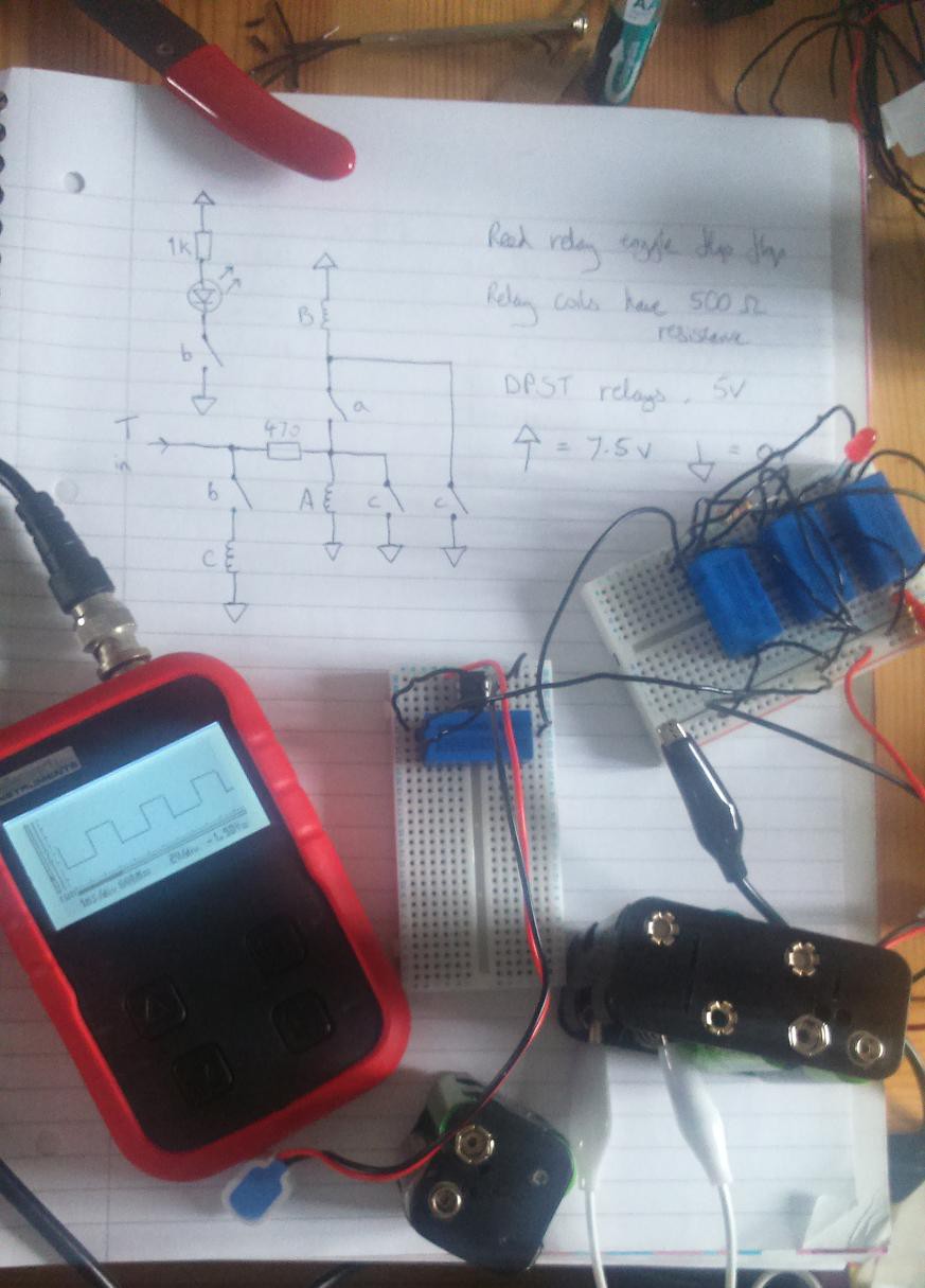
07/16/2016 at 20:38 • 0 commentsReed relays have a much faster switching time than armature relays. I purchased a few reed relays recently and used some to make a toggle flip flop. The relays have a switching time of about 1ms. This video shows the toggle flip flop operating:
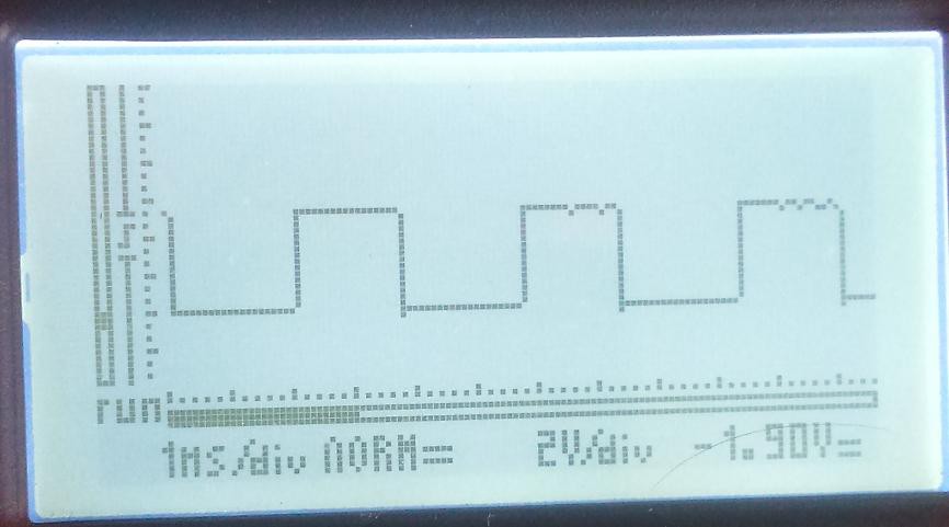
The reed relays used here are double pole single throw 5V relays with a 500 ohm coil resistance. Designing a toggle flip flop using single throw relays was a challenge.The photos below show that the toggle flip flop can be toggled at a rate of 625 Hz (the oscilloscope shows the output from the toggle flip flop - a 312.5 Hz square wave).
![]()
![]()
This has some relevance for DIY 3D printed relays: single throw relays are simpler to construct and have fewer design constraints. There is only one contact to worry about, and when the relay is in the open state, no part of the relay is under stress, so there is no opportunity for stressed parts to creep when the relay is off (a potential problem if using PLA).
-
Relay Testing
07/09/2016 at 22:13 • 0 comments![]()
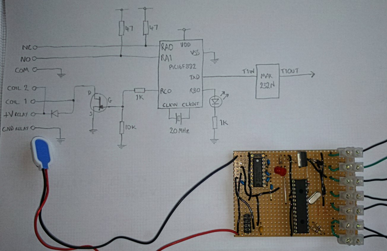
This circuit is used to measure how long it takes a relay to switch, and also to monitor the resistance of the relay contacts when closed. This is needed in order to assess and compare different DIY relay designs. Before making this I had been measuring relay timing using the digital IOs on a Raspberry PI. This has two problems: occasionally OS task switching interferes with timing measurement, and it doesn't monitor relay contact resistance. (Making a poor contact is a common relay failure mode).
The circuit is controlled by a PIC16F882 microcontroller. The PIC firmware toggles RC0 to switch the relay coil on or off, then continuously measures the voltage on either RA0 or RA1 depending on whether the coil is off or on respectively. Each of the relay contacts forms a voltage divider with one of the 47 ohm resistors connected to RA0 and RA1. The voltage measurement is sent to the RS232 interface at a rate of one measurement every 177 microseconds - about 5650 measurements per second. The LED in the circuit is simply an 'I am alive' indicator - it blinks twice when the circuit is powered on, but does nothing else.
The analogue-to-digital converter (ADC) in the PIC16F882 has a resolution of 10 bits. When the result is sent to the RS232 interface, this is split into two bytes. The first byte transmitted has the most signficant bit (bit 7) cleared, and the lower 7 bits are the lower 7 bits of the 10 bit ADC result. The second byte transmitted has the most significant bit set, and the lower 3 bits are the upper 3 bits of the ADC result. Therefore the laptop that collects the byte stream sent by the PIC can tell which byte is which by testing the most significant bit. The byte stream is turned into a CSV file.
The PIC source code (developed using MPLAB V8.76) can be found in relaytest/adc.asm in the relayreprap github repository.![]()
The graph above shows measurements from an OMRON G5LA-1 12V SPDT relay. At the start of this graph, the relay coil is on and the Normally Open (NO) contact is being monitored. The resistance of the NO contact is usually very low - between 50 and 100 milliohms. This is at the limit of what the circuit can measure. Just to the left of the centre of the X-axis the PIC turns the relay coil off and starts monitoring the resistance of the Normally Closed (NC) contact. Initially the contact is open and so the resistance goes off the top of the graph. After 5 milliseconds the contact closes, bounces for about 5 milliseconds and then remains closed. When closed, the reading from the ADC normally corresponds to a contact resistance of around 150 milliohms. When the relay coil switches on again (not shown on the graph), it takes about 4 milliseconds for the NO contact to close, with very little bouncing. Both the time and contact resistance are consistent with the relay specifications.
Sometimes the contact resistance appears to spike to a higher value - upto about 1 ohm. It's possible that this is noise rather than a real effect at the contact. -
Relays
06/01/2016 at 21:21 • 0 commentsDetails about a relay made from a 3D printed part, 3 nails and copper wire can be found here: http://relayreprap.srm.org.uk/#post3 . A photo is shown below:
![]()
The idea behind this particular arrangement of nails was that having the coil nail and the pole nail parallel would increase the force between them, compared with a non-parallel arrangement. I don't know whether this is true.
I recently tried another design that doesn't use parallel nails. Below are some photos:
![]()
![]()
Note that there is space for two relays in the 3D printed part, but only one is present in these images.![]()
The NC nail is a copper nail. I found that using a iron nail caused the pole nail to remain at the NC contact when the coil was activated.
This relay is easier to assemble than the previous design. It's less fiddly because the distance between the head of the copper nail and the head of the coil nail is determined by the 3D printed parts - it isn't adjustable. It also appears to have a lower contact resistance (both for the NC and NO contacts) than the previous design - about 1 ohm in each case, but this had yet to be fully characterized in tests.
Here is a video of this relay being tested: I'll post further details about relay testing in a future log entry.
-
Materials
05/30/2016 at 13:30 • 0 commentsIn this project I'm deliberately restricting myself to simple, easy to manufacture vitamin parts. They are shown in this image:
![]()
The parts and materials are: enameled copper wire, copper nail, iron nail (the nails I'm using are galvanized with zinc), solder, aluminium foil, PLA, water, and sodium bicarbonate.
How simple are the manufacturing steps involved in making each of these materials, and can they be simplified further?
Links to information about making PLA can be found on the RepRap wiki: http://reprap.org/wiki/PLA
It occurred to me recently that perhaps Gutta-percha (a naturally occurring victorian plastic produced by plants) could be used as a low-tech material for 3D printing. In the modern day it is used by dentists and can be purchased online.
There are 6 metals used here: copper, iron, zinc, tin, lead and aluminium. The first 5 of these have been smelted for thousands of years. The processes involved in smelting and shaping them are fairly straightforward and don't require high-tech tools. Extracting aluminium from its ore is a more complex process, first carried out in the 1820s. I'm using aluminium foil for the electrodes in DIY capacitors. It's possible that one of the other five metals would also work in this role, or that an alternative capacitor design could be used.
Sodium bicarbonate occurs naturally in large deposits in some parts of the world. My decision to use this for making capacitors is entirely arbitrary - it was one of the first thing that came up when I googled 'DIY capacitors', and I happened to have some in my kitchen cupboard. It's possible that salt water would work instead.
Regarding enameled copper wire: some ancient jewellery involved copper drawn into thin wires (I'm not sure how thin). I believe that enameled copper was invented around 100 years ago. I'm don't know what the process of enameling involves, and whether it is dependent on high-tech tools. In the 19th century electrical wire was insulted using fabric, paper and Gutta-percha. It is possible that PLA could be used for insulating copper wire, provided that the temperature of the wire never exceeds 60C. -
Electromagnets
05/30/2016 at 12:43 • 0 commentsThe relays used in this project use electromagnets made by coiling enameled copper wire around an iron nail. How many turns of wire should be used? What voltage should be used?
There are several factors to consider. From theory, the magnetic field strength inside the coil is proportional to both the number of turns and the current. For a fixed voltage, if the number of turns doubles, the current halves because the resistance doubles, and so the magnetic field strengh should stay the same. Because the power consumed is inversely proportional to the resistance, the power consumed halves. This favours a larger number of turns. Because the power consumed by the coil is proportional to the square of the voltage, ideally we should try to have a low voltage and a large number of turns.
In practice, a large number of turns takes up space, and the diameter of the coil gradually increases as the number of turns increases. Eventually a point of diminishing returns is reached, where increasing the number of turns decreases the efficiency of the electromagnet.
An issue related to the power consumption of the electromagnet is the temperature of the coil. Since electromagnets in the project will be mounted in PLA, we don't want the temperature of the electromagnet to exceed the glass transition temperature of PLA - about 60-65 C.
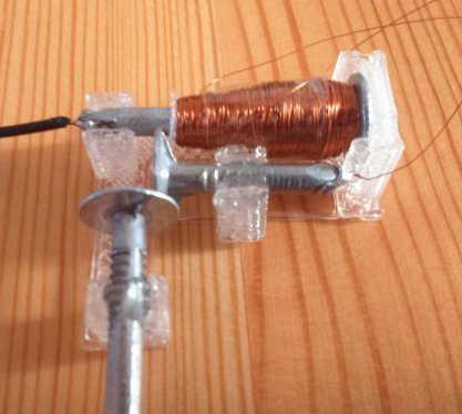
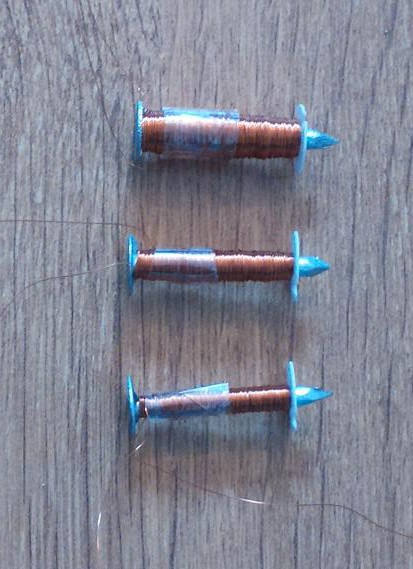
I made three electromagnets, one with 430 turns of wire, one with 860 turns of wire, and one with 1720 turns of wire (they were wound with the assistance of a hand drill, and these numbers correspond to 100,200 and 400 turns of the drill handle respectively). The nails are 30mm galvanized iron clout nails (the shiny kind, not the dull kind) with a diameter of 3.1mm. For these experiments, 24mm of the nail was wrapped with 40 swg enameled copper wire. See photo:![]()
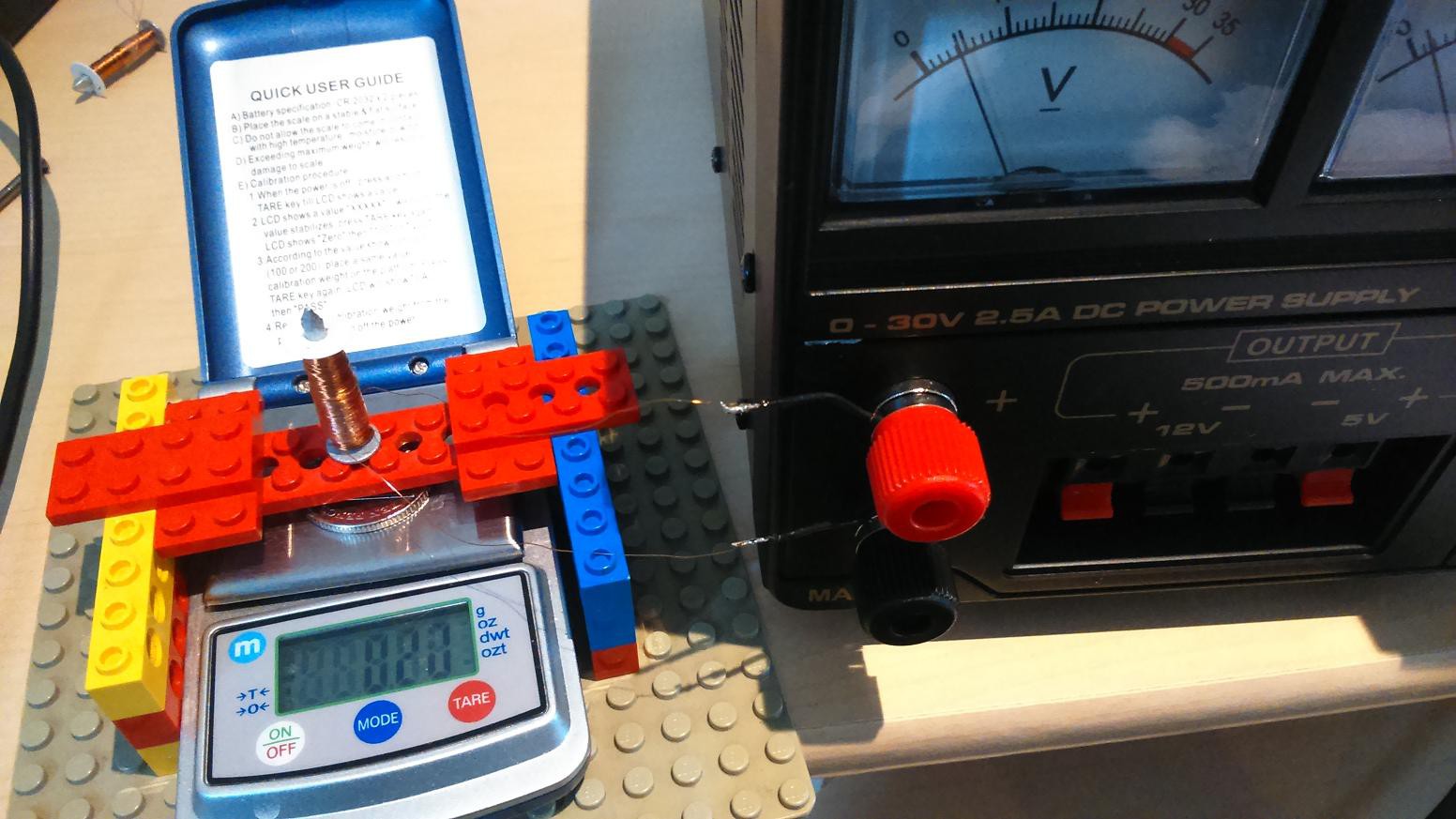
The following setup was used to measure the relative strength of each electromagnet:![]()
When power was applied to the electromagnet under test, the scale showed a reduction in weight of the coin on the pan. The reading from the scale was taken within a few seconds after power on. The reading gradually reduced over time because the coil heated up, increasing the resistance.
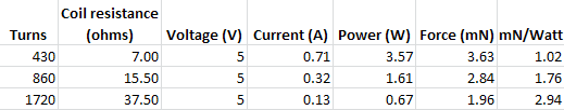
The table below shows the force exerted on the coin by each electromagnet.![]()
You can see that the resistance of the 1720 turn coil is more than four times that of the 430 turn coil - 5.4 times larger - because the diameter of the coil is larger on the outside than on the inside. But it doesn't look as though the 1720 turn coil has reached the point of diminishing returns yet.
A thermocouple was used to measure the temperature of the electromagnets. By holding the thermocouple in various places, I found that the place with the highest temperature was the centre of the head end of the nail. The room temperature was 20 C, the electromagnets were laid horizontally on a wooden tabletop.The 430 turn electromagnet reached 90 C after one minute, and the temperature was still increasing.
The 860 turn electromagnet reached 80C after 3 minutes, and the temperature was still increasing.
The 1720 turn electromagnet reached 53 C after 7 min, and the temperature seemed to have reached a steady state.
From these experiments, it seems that at 5V, anything much less than 1720 turns would get too hot (although in an active circuit, relays would probably have a duty cycle of about 50%, so the temperature wouldn't get as high as in this experiment). The number of turns hasn't yet reached the point of diminishing returns on efficiency. I have been able to make relays using electromagnets with 1720 turns of wire that will operate at 4V or greater. I used 40 swg copper wire because it is what I happened to have on my shelf. It seems worth exploring wire with a larger diameter - this might permit a lower voltage to be used, and reduce the power consumption. -
Motors
05/29/2016 at 21:26 • 0 commentsThis project is primarily concerned with making a relay-based controller for a RepRap, but the motors must also be considered, since the type of motor used determines the control signals required.
At the outset of this project I had intended to use stepper motors made from 3D printed parts and other materials. Googling '3D printed stepper motor' brings up a couple of motors constructed in a similar way.
Since I want to avoid using any more materials than necessary, I would like to avoid using permanent magnets. That means making a stepper motor using PLA, nails and copper wire. My guess is that making a stepper motor with a high enough torque using these materials would be challenging, and I suspect that the resulting motor would be very power hungry.
When reading up on existing RepRap mechanical arrangements, I came across this diagram of a mechanism for moving a bed in the Y-direction: http://forums.reprap.org/read.php?2,377858,601938#msg-601938 . By replacing the green fixed point on the right hand side with a second motor, the result is a mechanism that can move back and forth in the Y direction, but where each motor only needs to turn in one direction. This video illustrates the mechanism:
So there is no need to make bidirectional stepper motors. Since the motors only need to rotate in one direction, why not use gravity as the power source rather then electricity? All that is needed, then, is a weight attached to a spool on a shaft, with the rotation of the spool controlled by a stepping device. This video shows a prototype:
The control signals required for a bidirectional linear mechanism driven by two of these gravity powered unidirectional motors (GPUMs) are much simpler than those required for a conventional stepper motor. The simplest relay-based conventional stepper motor driver than I was able to come up with has 14 SPDT relays: This driver has direction and step inputs. A bidirectional mechanism driven by GPUMs requires only 1 SPDT relay to give equivalent functionality - the direction input causes the relay to direct the step input to one GPUM or the other.
N.B. In the video of the GPUM shown earlier, the shaft is powered by a falling weight. This is what I plan to use in all prototypes. The disadvantage of this, of course, is that eventually the weight will hit the floor. Looking further forward, the shaft could instead be powered by an on-demand waterwheel (i.e. a waterwheel where the water only flows when power is taken from the shaft). -
Progress so far...
05/27/2016 at 20:24 • 0 commentsI started this project in January this year, having thought about it on-and-off for a couple of years. At the time of entering this project onto Hackaday IO, I've done the following:- Made a relay from PLA, 3 galvanized iron nails, enamelled copper wire, solder, sellotape, epoxy glue, and connecting wires.
- Wrote a relay testing program for the Raspberry PI. It tests the operation of a relay for a specified number of cycles, and times how long it takes the contacts to open and close. It detects if a contact fails to open or close when expected.
- Established that a clock circuit can be made using (off-the-shelf) relays, and capacitors made from sodium bicarbonate, water and aluminium foil.
- Established that it may be possible to use a sodium bicarbonate capacitor as a snubber to reduce arcing at relay contacts.
- Made some counter circuits using off-the-shelf relays. This includes a circuit that would be capable of controlling a simple 2D plotter, programmed with a punched tape (made from PLA). The file 'controller_explanation.pdf' describes this circuit.
- Made an actuator from the same materials as the relay, used this actuator to step a gravity powered motor.
- Worked out how to get bidirectional linear motion from two unidirectional gravity powered motors.
RelayRepRap
This project is about exploring whether it is possible to make a RepRap control system that can be made by a RepRap.