 aaronbehman
-
1Step 1
1 . O v e r v i e w
This specification describes the procedure to write the following data to QSPI Flash and eMMC on Smart Vision Development Kit (SVDK).
Data to be written to QSPI Flash:
- BOOT.bin
- image.ub.bin
Data to be written to eMMC:
- rootfs_emms.tar.gz
- Firm.bin
- BS.dat
- DU.dat
- XML.dat
-
2Step 2
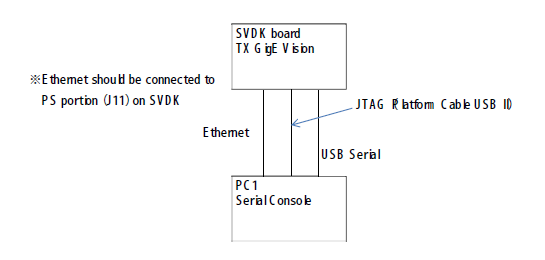
2. Connection Overview
Connection environment is as shown below:
![]()
![]()
-
3Step 3
3. Writing Procedure
3-1. Witting to QSPI Flash
- Connect PC and SVDK board with JTAG (Platform Cable USB II).
- Turn on the power of SVDK board.
- Boot up Xilinx SDK 2015.4, Windows version.
- Unzip [QSPI_Write.zip] in [¥02_PCTool¥02_DataWriteTool] folder of downloaded file, and open the following workspace using SDK.
- QSPI_Write¥sdk_workspace
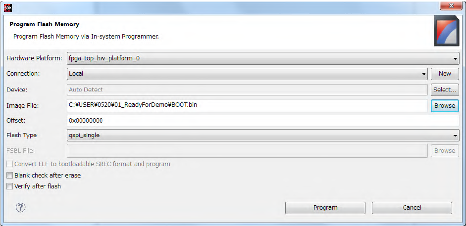
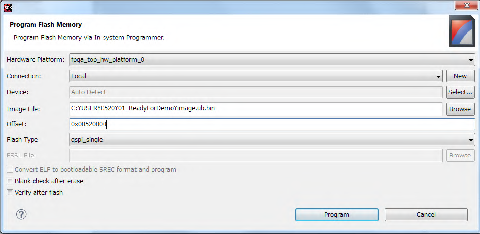
- Write the following two files (from download file) to QSPI, by using Xilinx SDK 2015.4 tool bar, Xilinx Tools
- Program Flash. It will take 3 minutes with BOOT.bin and 7 minutes with image.ub.bin for writing.
・¥01_ReadyForDemo¥BOOT.bin
・¥01_ReadyForDemo¥image.ub.bin
Where to write (offset) are as follow
- BOOT.bin 0x00000000
- image.ub.bin 0x00520000
![]()
![]()
6. Turn off the SVDK board.
7. Close Xilinx SDK 2015.4.
8. Disconnect JTAG(Platform Cable USB II)from SVDK board.
3-2. Writing to eMMC
- Connect PC and SVDK board (PS portion) with LAN cable.
- Connect PC and SVDK board with USB serial cable.
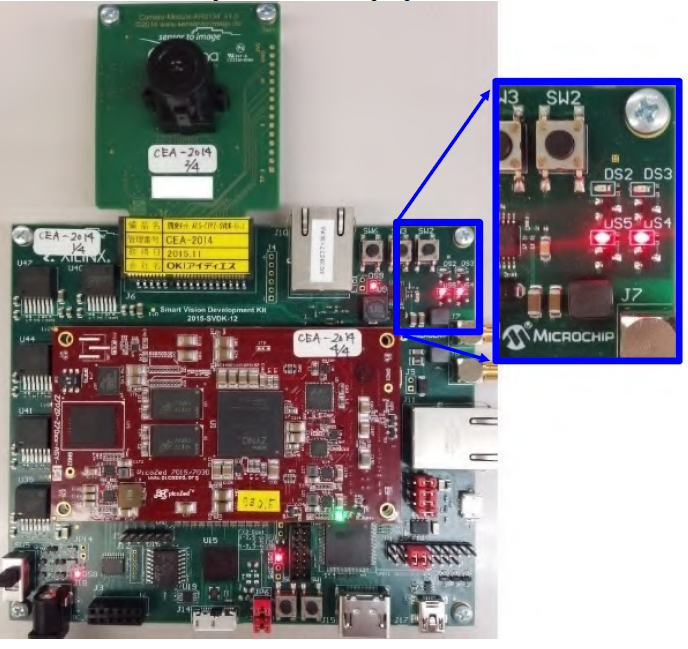
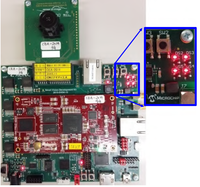
- Turn on the power of SVDK bard, and wait until the two LEDs (DS4, DS5) turn on, per fig 3-1 below.
(Note: LEDs flickers for a second soon after Power On. Please wait a while until the lights turn on)
If the 5 data are already written to eMMC, 2 LED light turns on, followed by additional 2 lighting on, and all
4 LEDs turn on showing the board is boot up, per the fig 3-2 below.
Fig3-1: State of 2 LEDs lighting
![]()
Fig3-2: State of all 4 LEDs lighting on
![]()
-
4Step 4
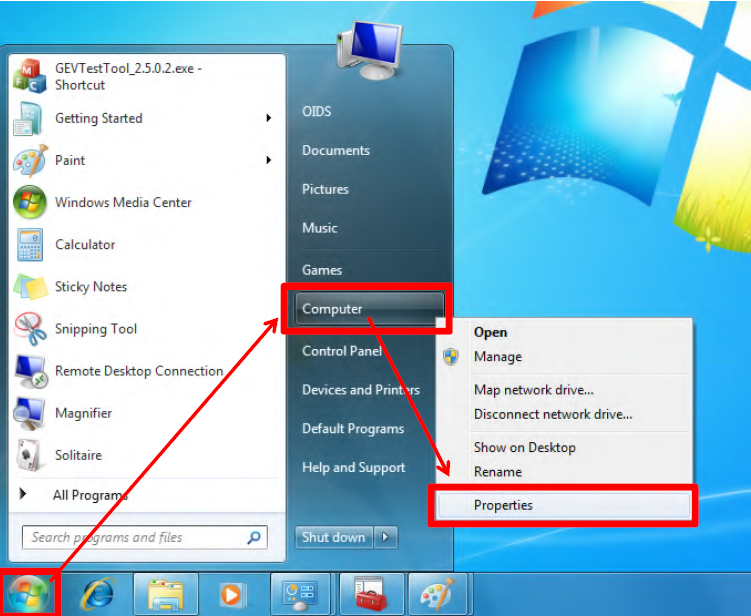
4. Confirm COM port number (shown below is an example of Windows7)
1) Right click [Computer] from Windows Start menu, select [Properties] from pull down.
![]()
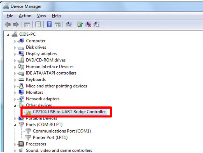
2) Select [Device Manager].
![]()
3) If it indicates as marked by red, (“Silicon Labs CP210x USB to UART Bridge (COMx)”), check and remember the COM number (required in the later steps). In the example below it’s “3”.
![]()
4) If It’s indicated as follows, you will need to install the driver. After the installation, check and remember the COM number shown.
![]()
(5) Create FAT32 partition of 512MB in eMMC.
1) Turn off and on the power of SVDK board, and wait until two LEDs (DS4, DS5) turn on, per fig. 3-1 above. (After the power on, the LEDs flicker a second. Wait a while until the 2 LEDs turn on)
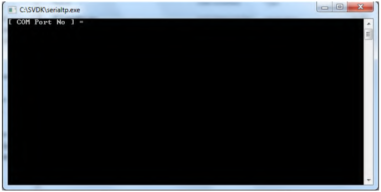
2) Double click [serialtp.exe] in the [¥02_PCTool¥02_DataWriteTool] folder downloaded.
3) Screen shows up as follows:
![]()
4) Type in the COM number confirmed at step(4)above and hit return.
5) Wait until the process completes.
- If the process completes successfully, “SUCCESS:setting OK” shows up (per image below). Hit any key to exit.
- If “ERROR:res recv error” shows up, please turn off the power of SVDK board and restart from 1) above. If the process won’t compete successfully with several tries, follow the step described on
Appendix-A to create FAT32 partition manually.
![]()
(6) Turn off and on the power of SVDK board and wait until two LEDs (DS4, DS5) turn on, per fig 3-1 above.
(After the power on, the LEDs flicker a second. Wait a while until the 2 LED turn on)(7) Transfer 5 data from PC to eMMC of SVDK board.
1) Set the IP address on PC as 192.168.1.20.
2) Double click [¥ 01_ReadyForDemo¥ftp_send.bat] of downloaded file.
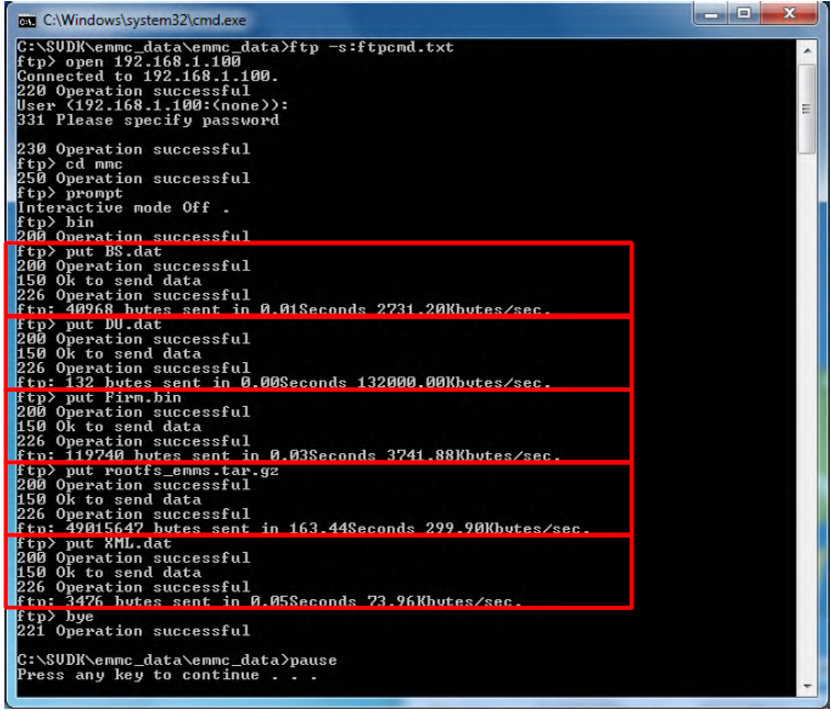
3) Wait until the transfer of 5 data (BS.dat, DU.dat, Frim.bin, rootfs_emms.tar.gz, XML.dat) completes. (until it outputs as the image below, in 2 or 3 minutes)
Hit any key to exit
![]()
(8) Turn OFF and ON the power of SVDK board.
-
5Step 5
Appendix A:
Described below is the procedure for creating FAT32 partition on eMMC by manual operation. Please follow the steps shown below in case the procedure of Section 3-2 (5) above does not work, as an alternative measure to create partition.
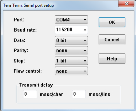
(1) Start up the serial console and make settings. Shown below is an example of setting screen in case of using Tera Term.
![]()
(2) Turn on the power of SVDK board and wait until two LEDs (DS4, DS5) turn on, per fig 3-1 above.
(After the power on, the LEDs flicker a second. Wait a while until the 2 LEDs turn on)
(3) Login and pass word will be required. Type login and password as follows;
Login: root
Password: root
![]()
(4) Type in ’fdisk /dev/mmcblk0’
![]()
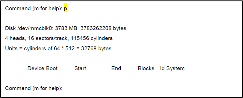
(5) Type ’p’.
![]()
(6) Type ’n’.
![]()
(7) Type ’p’.
![]()
(8) Type ’1’.
![]()
(9) Type ’1’.
![]()
(10) Type ’+512M’
![]()
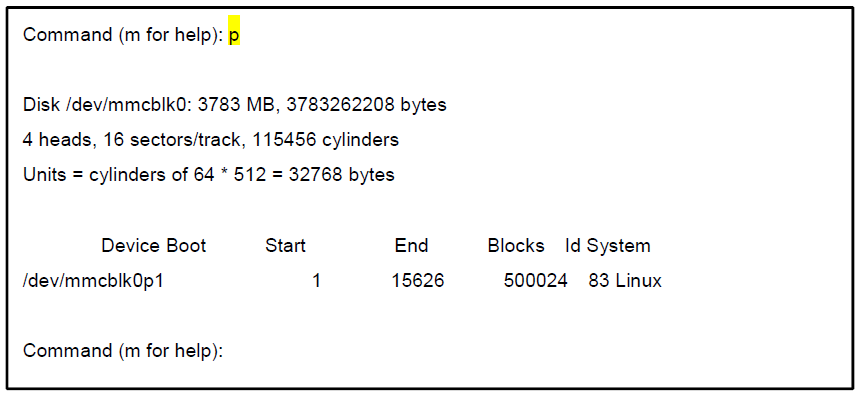
(11) Type ’p’.
![]()
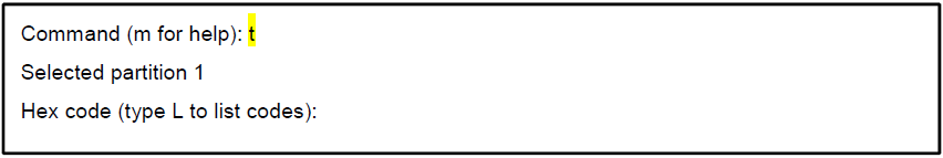
(12) Type ’t’.
![]()
(13) Type ’b’.
![]()
(14) Type ’p’.
![]()
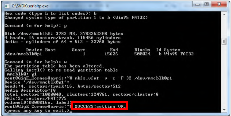
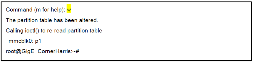
(15) Type ’w’.
![]()
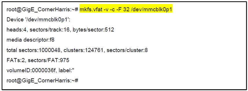
(16) Type ’ mkfs.vfat -v -c -F 32 /dev/mmcblk0p1’.
![]()
Software Defined Vision System
GigE Vision SDSOC Platform for Xilinx SVDK Kit Evaluation Demo


Discussions
Become a Hackaday.io Member
Create an account to leave a comment. Already have an account? Log In.