Close
0%
0%

A-BRIDGE

Dual 3.5A motor driver with built-in signal inverter for LAP control.

Similar projects worth following
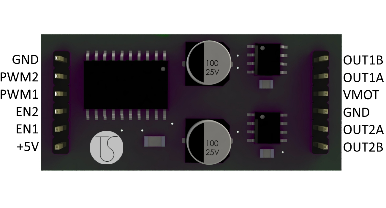
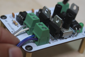
The A-Bridge is a small dual H-BRIDGE based on the integrated DMOS full-bridge A5950, capable to drive 2 motors with a continuos current of 3A (3.5 with a heatsink) and a peak current of 5A. The bridge operates in PWM LAP, so, compared to the typical PWM SM control, you have less resolution but a more precise control of the speed. The inverted PWM signal required for LAP control is generated internally with a 74HC240 tri-state inverter, that also gives you the possibility to disable the bridge and the motor using the Enable input.

Features:
- Drives 2 brushed DC motors
- Input voltage: 8-40V
- Output current: 3A continuos, 3.5 if dissipated, 5A peak
- Overcurrent short circuit protection
- Enable input to disable the bridge
- Size: 20x45 mm

Buy A-Bridge on Tindie:
https://www.tindie.com/products/s-tolomei/a-bridge-dual-35a-moto

The circuit is very simple, basically it consists of two A4950, the 74HC240 and five bulk capacitors.

The ENABLE pin of the inverter is used to set LOW both the Input signals of the A4950, setting it to low power mode.

The A4950 can also provide a current feedback, but the sensing resistor also triggers the automatic current limiting system of the IC, that decrease the maximum output current. For example, a 0.25ohm resistor would limit the maximum current to 2A. This is the reason why i choose not to use the current sensing in this version of the board. If you want to use the current sensing feature you can use a external ammeter IC or consider the powerful uBridge by Officine Robotiche.

How to use

Basically this is a H Bridge, the only difference between this and the other typical commercial bridges is the integrated LAP control, this mean that you can control both speed and direction using the same signal. In particular:

PWM duty cycleMotor speed
0%Full Backwards
50%Brake
100%Full Forwards

The ENABLE pin is used to disable the bridge. When LOW the bridge is operating at normal condition, when HIGH the bridge will enter in low power standby mode after 1ms. This is useful because the brake condition, with duty cycle 50%, means that the motor is braked, and it will draw current to remain still. This is the worst efficiency condition for the bridge, then, unless with small motor, it will heat up very fast. I recommend you not to remain in brake condition for more than a half a minute. Therefore, for simply stop the motor you can set duty cicle to 50% and then disable the bridge with EN pin.

A-BRIDGE.brd

brd - 1.00 MB - 12/29/2016 at 13:43

Download

A-BRIDGE.sch

sch - 570.17 kB - 12/29/2016 at 13:42

Download

A-BRIDGE.emp

emp - 1.56 kB - 06/28/2016 at 11:15

Download

  • 2 × A4950 Power Management ICs / Motion, Motor and Servo Control
  • 1 × 74HC240 Electronic Components / Misc. Electronic Components
  • 1 × 100nF Capacitor Capacitors, SMD
  • 2 × 220nF Capacitors Capacitors, SMD
  • 2 × 100uF Electrolytic Capacitors Capacitors, SMD

View all 6 components

  • Testing and Selling!

    Simone Tolomei08/09/2016 at 08:42 0 comments

    Finally i started selling the boards on Tindie! Take a look HERE

    I take this opportunity to pubblish the results of the tests.

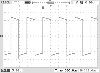
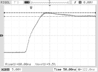
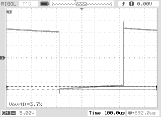
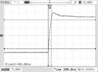
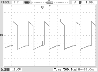
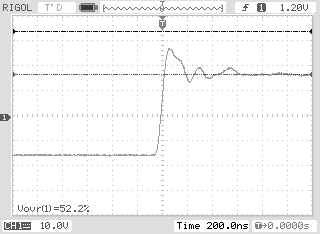
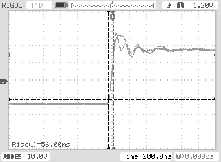
    The tests measures voltage drop, voltage overshoot, rise time and temperature. Here you can see differents measures obtained with 2 different motors: a micromotors 12V 300mA geared motor and a lawnmower motor, running at 20V and absorbing 600mA with no load.

    The tests is done at the worst condition, that is 50% of duty cycle and 1Khz of PWM frequency. Increasing the frequency will increases the efficency of the bridge. In particular, to use big motors i recommend to use a PWM frequency at least of 10-15Khz, for example by using the setPwmFrequency function on Arduino or by using another microcontroller (e.g. ARM or PIC)

    Here you can see the different measures done on the output signal.

    MICROMOTORS MOTOR (temp: ~ 40°C)

    LAWNMOWER MOTOR (temp: ~ 70 °C)

    Now i started designing the next version of the board (which includes better heat dissipation, power supply LED, and much more) and a shield adapter for Arduino, which enables you to use the A-BRIDGE with Arduino Boards

    Simone Tolomei.

View project log

Enjoy this project?

Share

Discussions

Hanna Sarvilian wrote 03/24/2021 at 09:06 point

By reading the details about the A-Bridge, I am totally convinced now that I should make the decision of investing in it. Hopefully, this product would be able to provide the same benefits as what it is talking about. I have been thinking to visit the home of an authentic website where I could read the reviews of essay writter before hiring him for help in an essay that I am writing about this topic.

  Are you sure? yes | no

Similar Projects

Does this project spark your interest?

Become a member to follow this project and never miss any updates