-
The Final PCB Version is Ordered
08/27/2016 at 16:16 • 0 commentsYup, that's right. The PCBs are now ordered, expected arrival in about a week.
Sourcing of components have started as well. Between building, testing and photographing the latest version so that instructions can be created, and stuffing the components, I hope to be able to offer a kit some time in the beginning of October.
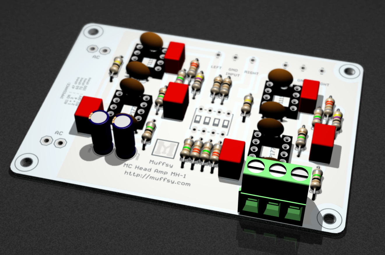
Here's the latest rendering:
-
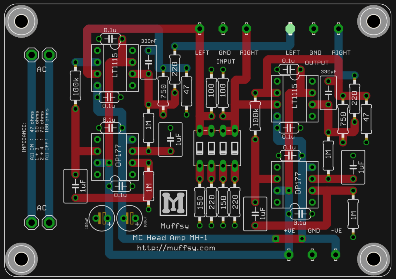
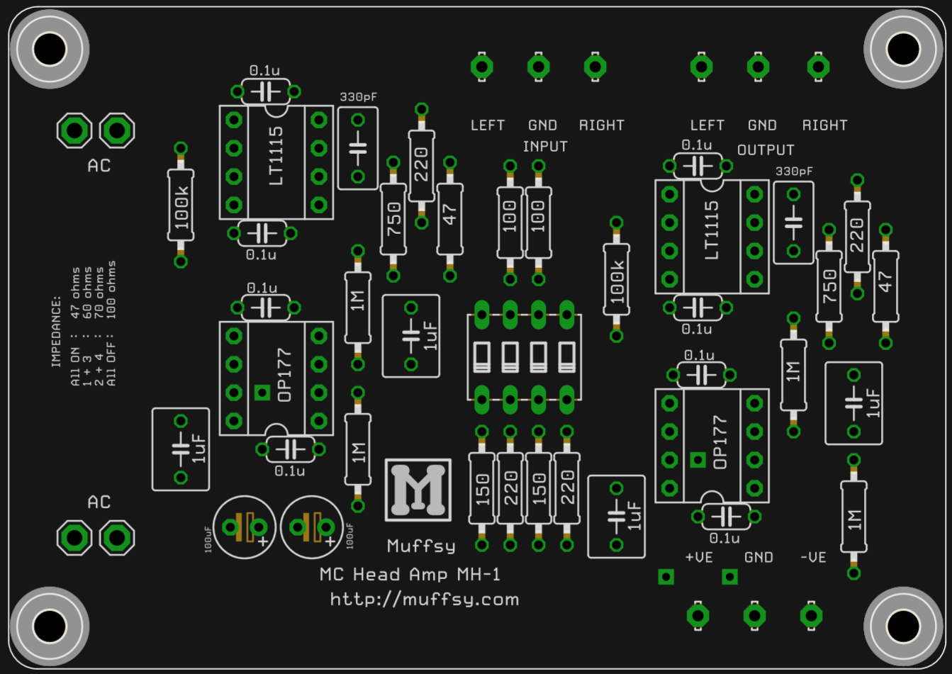
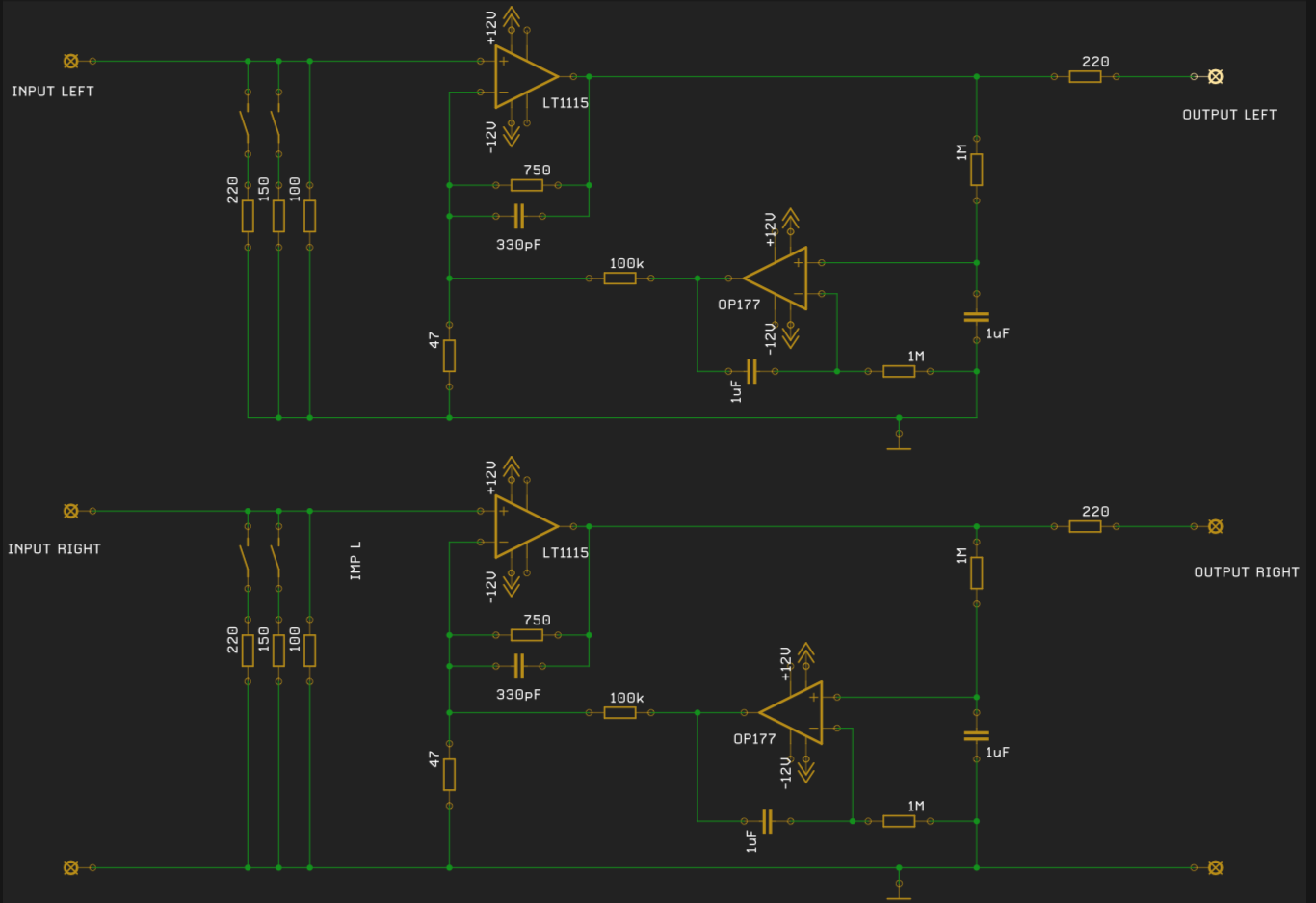
Muffsy MC Head Amp - Final Design
08/07/2016 at 17:02 • 0 commentsThis is the final design of the Muffsy MC Head Amp MH-1, after two prototypes (number 1 and number 2) and lots of testing and measurements.
The project front page has been updated with these new pictures.
First a rendering:
![]()
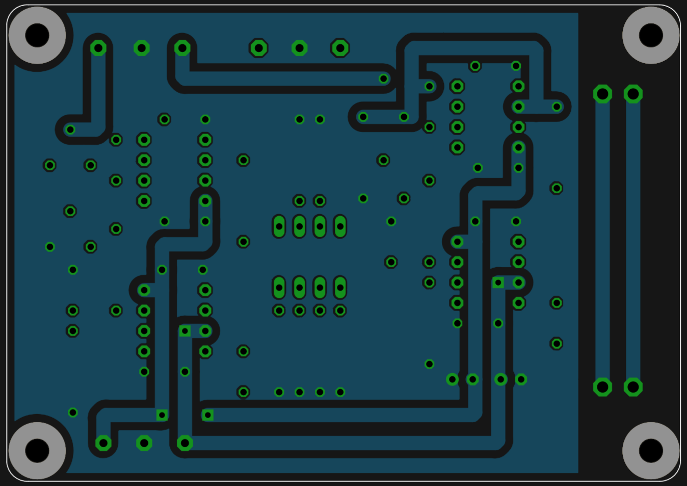
PCB Layout, top and bottom without ground:
![]()
PCB top, with ground:
![]()
PCB bottom, with ground:
![]()
Silkscreen:
![]()
Circuit Schematic:
![]()
-
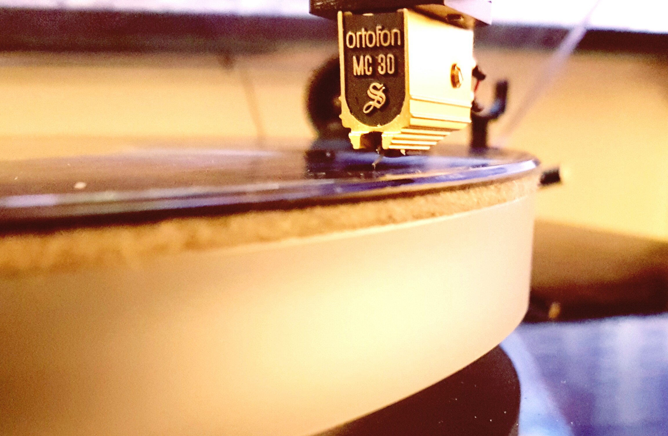
The Muffsy MC Head Amp is Alive!
08/03/2016 at 08:53 • 3 commentsI got an MC cartridge, a nice little Ortofon MC30 Supreme:
![]()
Connecting the turntable to the Muffsy MC Head Amp and then to the Muffsy Phono Preamp. nothing but sweet silence.
Then the needle dropped, and the silence turned to sweet, sweet sound. This little rascal performs way beyond what was expected with a deep black background, rich and detailed sound and a fantastic sound stage.
A kit is getting closer, but a lot of components have to be sourced and the final PCB has to be ordered and tested.
-
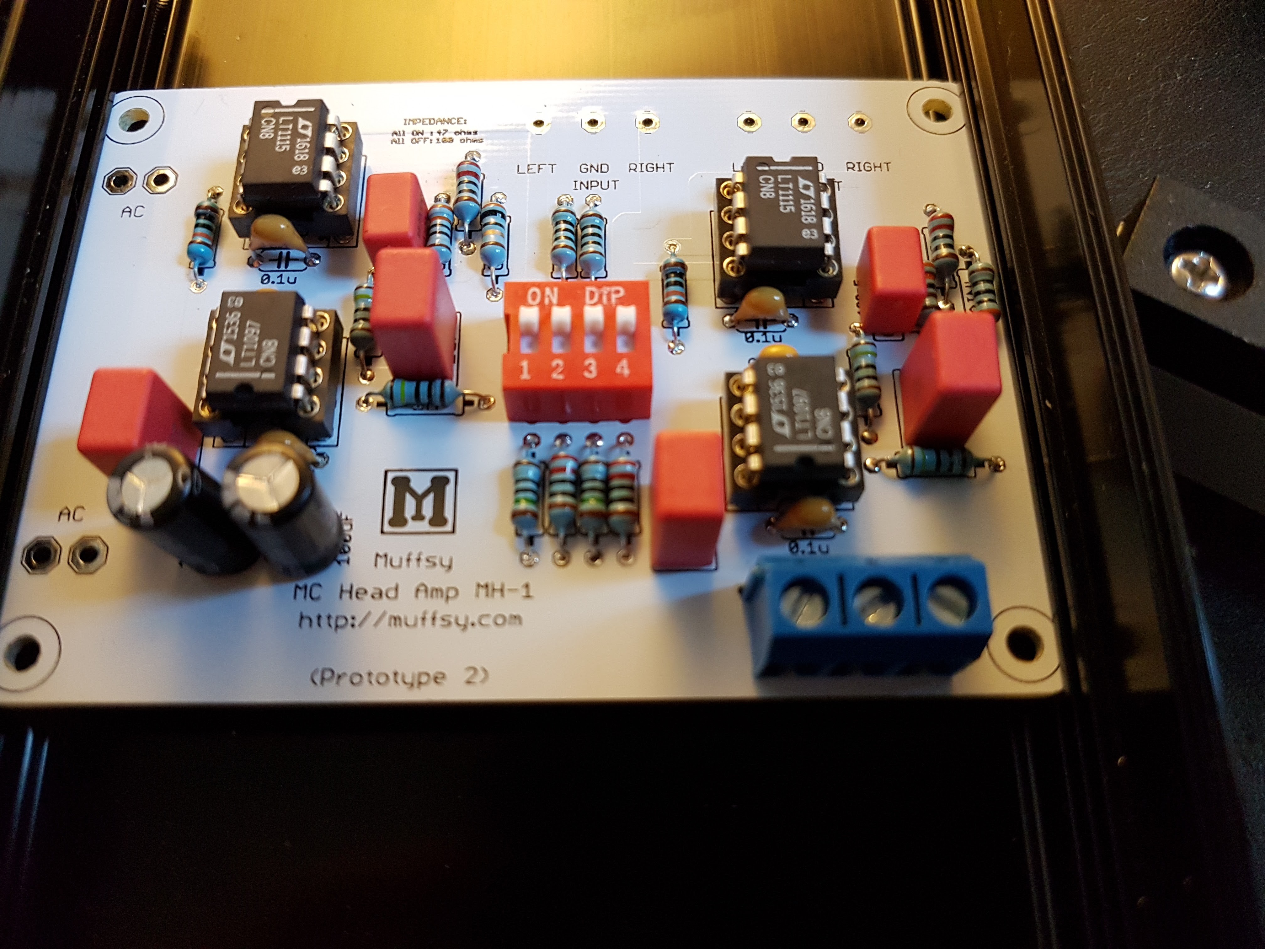
Testing the Prototype 2
07/22/2016 at 08:22 • 0 commentsThe Muffsy MH-1 Prototype 2 has been soldered, and it's time for some testing.
- Both channels (yes, it's dual mono) use LT1115, with LT1097 and OP177 as DC servo, testing is done with 750/47 ohms gain resistors and 100 ohms input impedance.
- Input signal for testing: 0.5 mV
Here are all the tests:
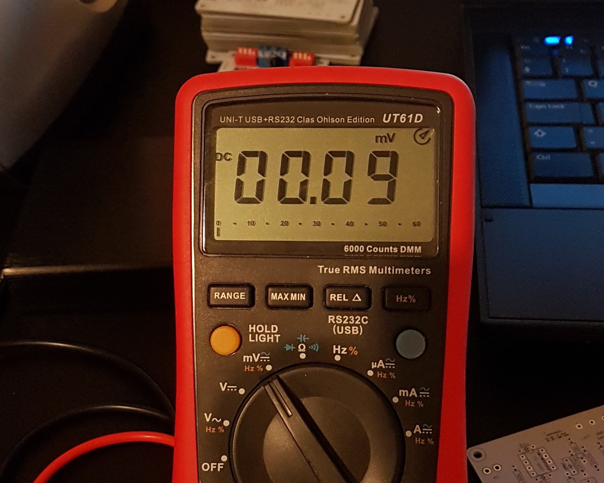
- DC offset: < 0.1 mV. Similar performance with OP177:
![]()
- Circuit does not oscillate
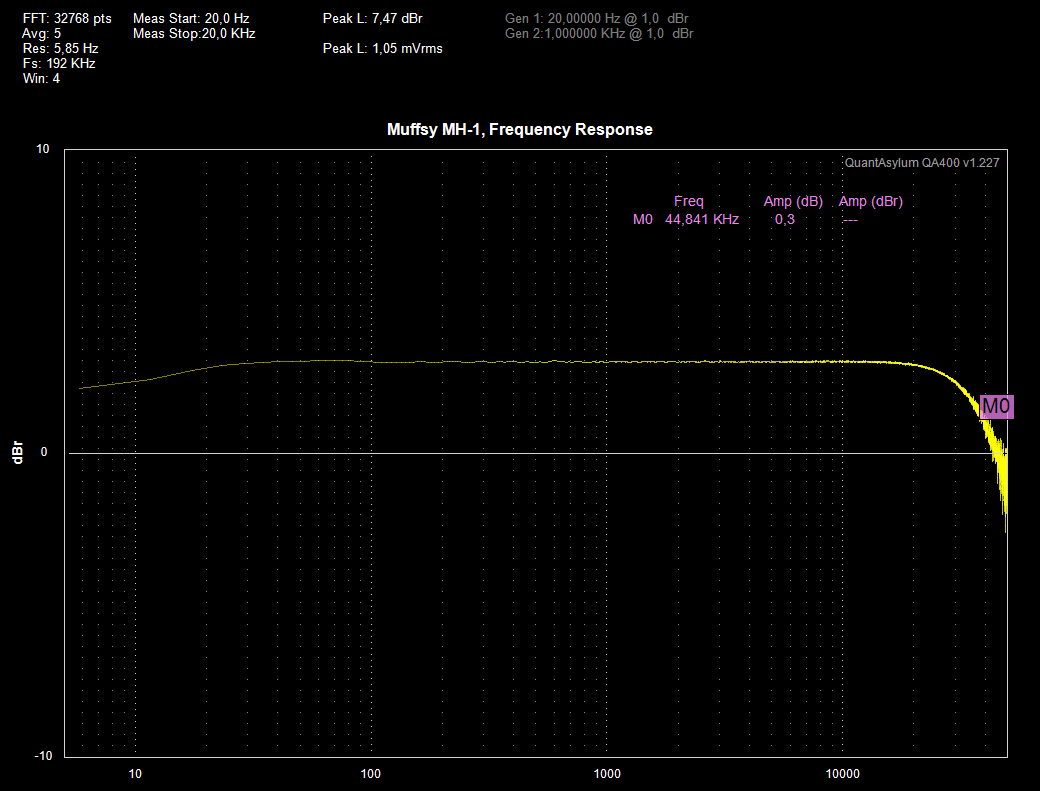
- Frequency Response (graph shows the -3 dB point at 0 dBr):
- 20 - 20.000 Hz: +0.0 / -0.1 dB
- 1 - 45.000 Hz: +0 / -3 dB (irrelevant because of the QA400's frequency response, see below)
![]() The frequency response drops off to -3 dB at ~45 kHz. This seems to be a limitation of the QA400 which has a loopback frequency response of, you guessed it, 45 kHz. The -3 dB point as defined by the low pass filter in the gain network should be around 300 kHz.
The frequency response drops off to -3 dB at ~45 kHz. This seems to be a limitation of the QA400 which has a loopback frequency response of, you guessed it, 45 kHz. The -3 dB point as defined by the low pass filter in the gain network should be around 300 kHz.
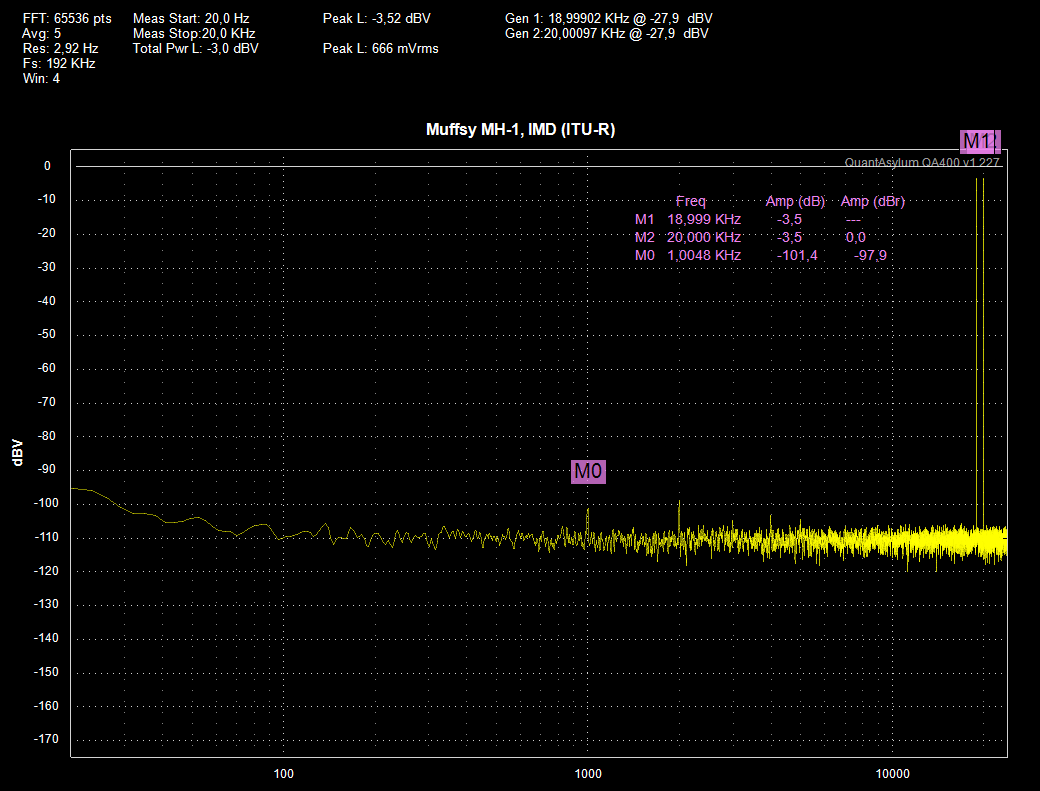
- IMD (ITU-R): 0.001 % (difference between 19/20 kHz pair and 1 kHz mixing product: -97.9 dB)
![]() The value of the Intermodulation Distortion is of somewhat academic interest. In reality, the 1 kHz result will be way below the noise floor of the Muffsy Head Amp; I had to increase the input signal by almost 40 dB to even find it.
The value of the Intermodulation Distortion is of somewhat academic interest. In reality, the 1 kHz result will be way below the noise floor of the Muffsy Head Amp; I had to increase the input signal by almost 40 dB to even find it.
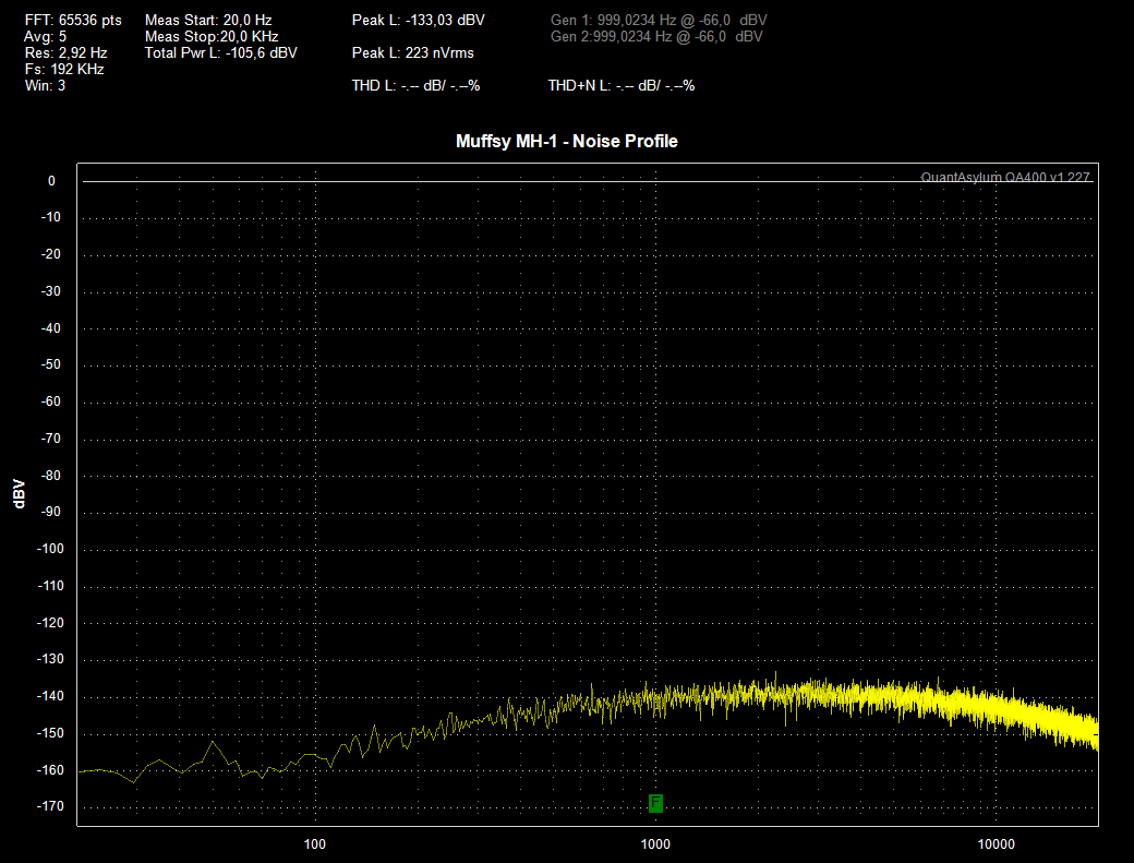
- Measured noise profile:
![]()
- Overall noise is -105.6 dB (20-20.000 Hz)
- Peak noise value: -133.03 dBV
- Output with 0.5 mV input: 8.5 mV / -41.44 dB
Hmmm... What's with these measurements?
The SNR, according to these readings, is 64.2 dB. But theoretically, it should be over 70 dB...
I get the exact same measurements with nothing connected to the QA400, and the specifications say that its input noise performance (20-20.000 Hz) is 102/104 dBV (low/high impedance). Add 3 dB for A-weighting. I've hit the limits of the QA400... This tells me that the SNR must be greater than, or equal to these measurements.
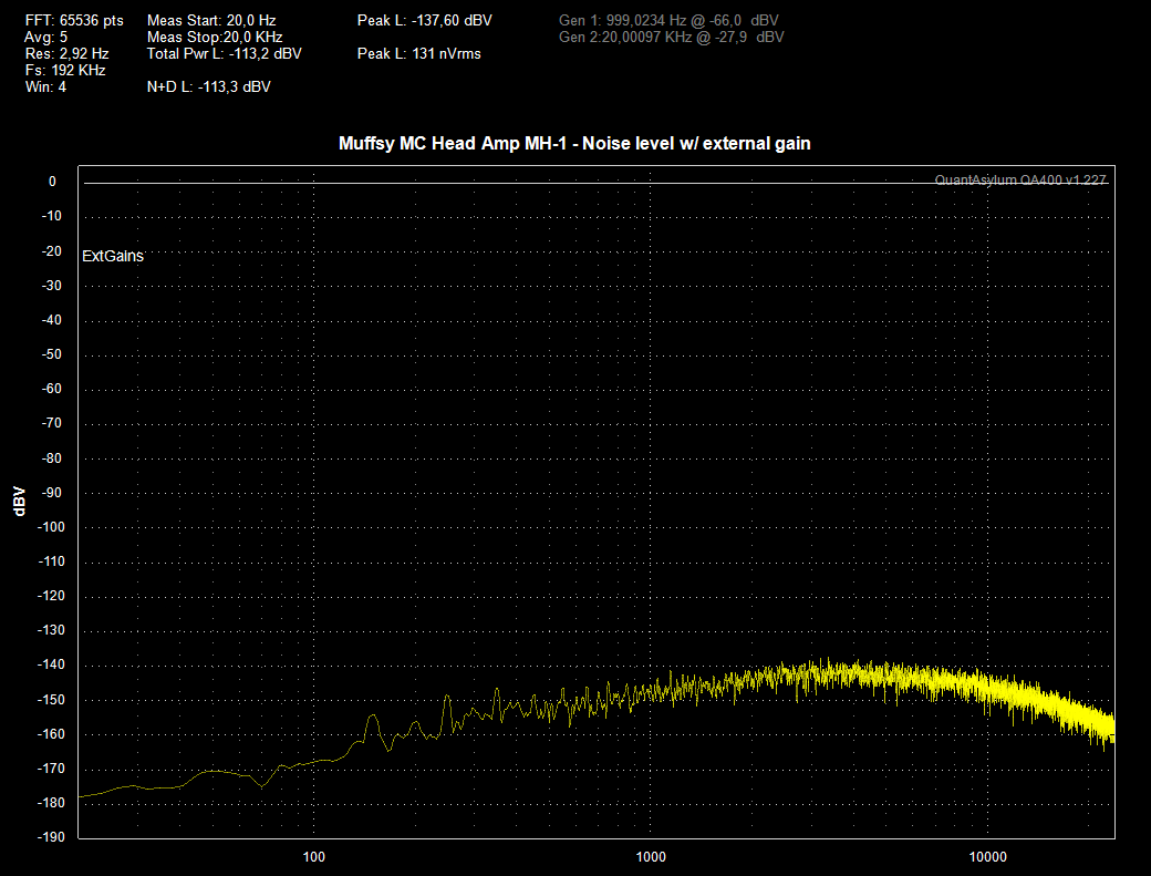
How much better, I can't exactly tell. I do know that the LM4562 in Prototype 1 measured just shy of the 60 dB it was supposed to according to the calculations, which also is on the limit of the QA400's abilities, so I can only guess that the Prototype 2 performs according to the calculated value, which is 72 dB. It should at least be greater than 70 dB.I have redone the noise measurements, using the Muffsy MC Head Amp itself to lower the noise floor according to this article: http://www.quantasylum.com/content/Home/tabid/40/Post/205/Extending-the-QA400-Noise-Floor-with-a-Pre-amp
![]()
I can now tell exactly what the signal-to-noise ratio is for the Muffsy MC Head Amp is:
113.2 dBV (total noise) - 41.4 dB (signal strength) = 71.8 dB
- THD / THD+N
With an SNR of at least 70 dB, the noise floor of the Muffsy MH-1 is at the very least 5.8 dB below that of the QA400. So I'm increasing the input signal by 5.8 dB to take that into account.
- THD: < 0.1 %
- THD+N: < 0.6%
![]()
- Connecting the Muffsy MH-1 to the stereo
This is quite the test. The first prototype made some noises, so fingers crossed.
I connected a 0.5 mV signal to both channels to see if it did what it was supposed to do, disconnected the signal and hooked up the MH-1 to my stereo on the input with the Muffsy Phono Preamp (with the volume off, of course).
I turned up the volume very slowly, no sound (yay!), then further and further until I had reached max volume.
There was a very tiny, minuscule white noise sound that could only be heard by pressing the ears into the loudspeaker. I think that could be called a successful test. :)
![]()
The first test was with 100 ohms input impedance, I tested again with 50 ohms and got the exact same great result. The test was done with LT1097 as DC servo, I'll redo the test with OP177 as well.
But... Here's the thing... I don't own an MC cartridge... I should be able to solve that though, stay tuned.
Well, I got an MC cartridge and the Muffsy MC Head Amp sings. And it's every bit as good as I hoped for, and then some!
-
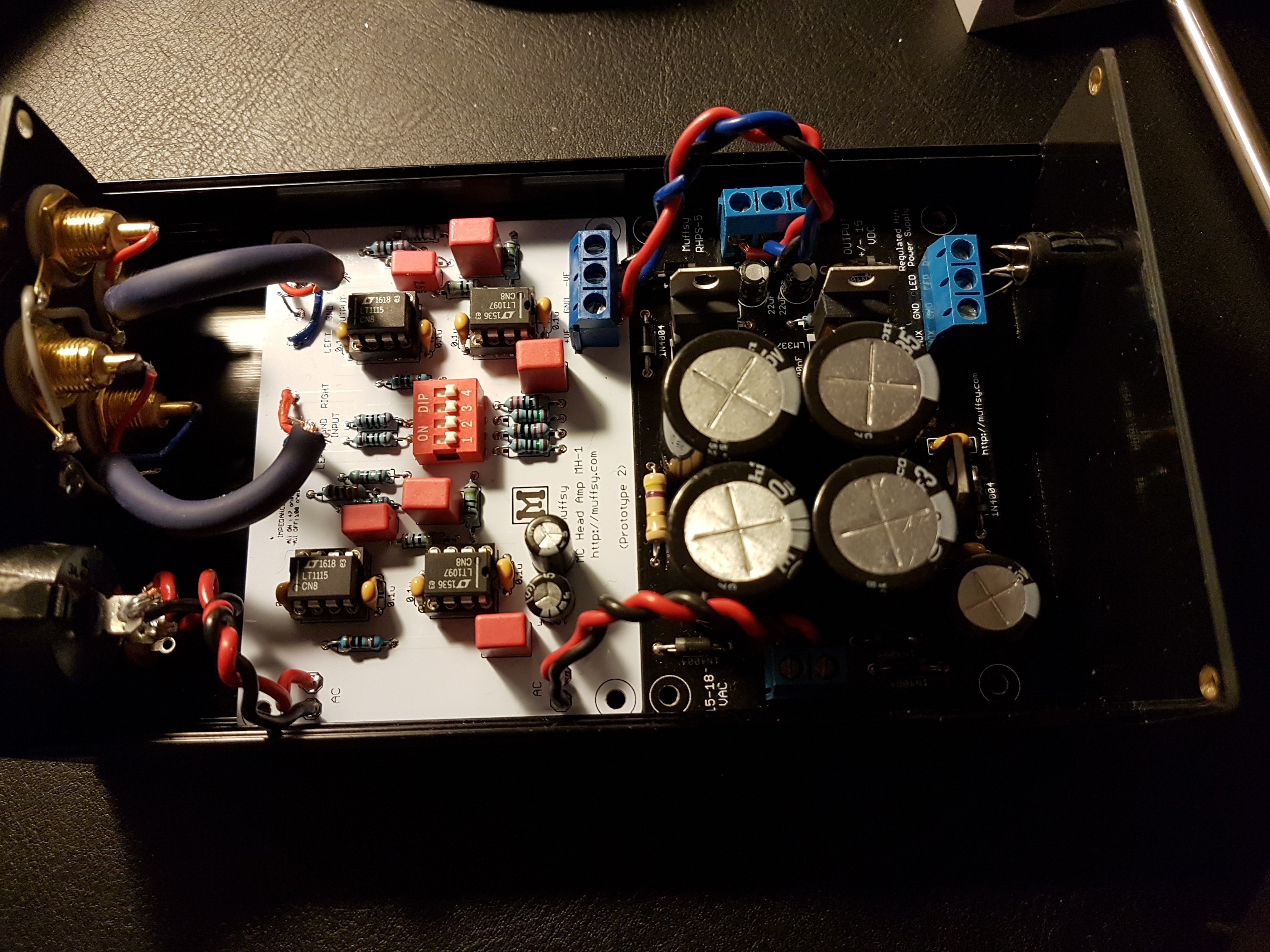
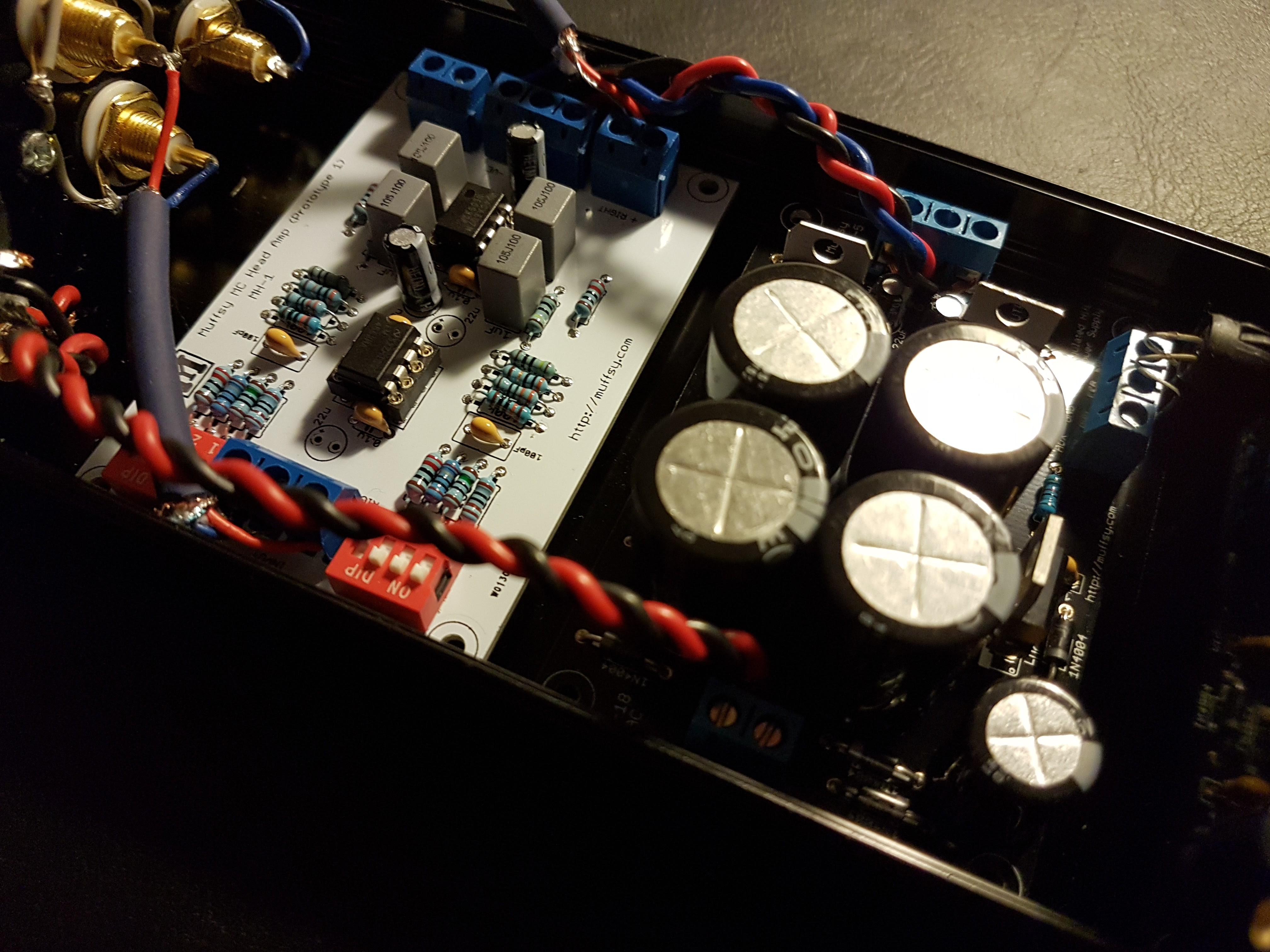
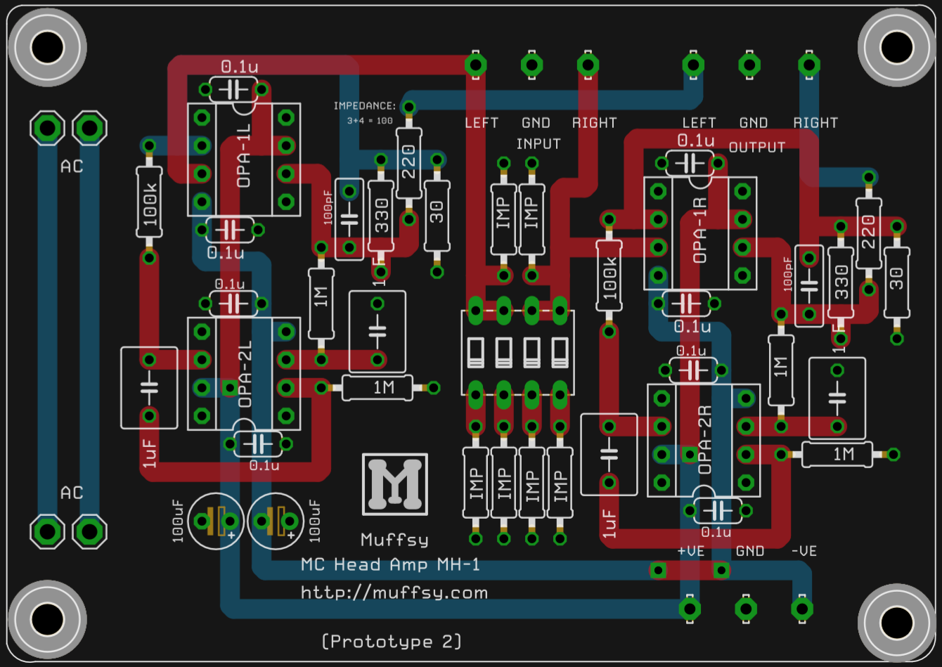
Prototype 2 - Soldered
07/21/2016 at 20:42 • 0 commentsAll the components are in place, now it needs to be mounted in a case and powered up. Notice that there are no screw terminals on the input/output. Since those are rather sensitive areas when it comes to interference, it will be best to solder the shielded cables directly to the board.
![]()
There will be a few cosmetic changes of the layout. The 100uF electrolytes didn't quite fit, the same with the 100pF film caps. The gain network of the LT1115 op amps was changed a bit to get some more distance from the cabinet walls. I've also added ground fill on the top of the board, and removed it completely around the AC throughput traces. Here's how it looks as of now:
![]()
-
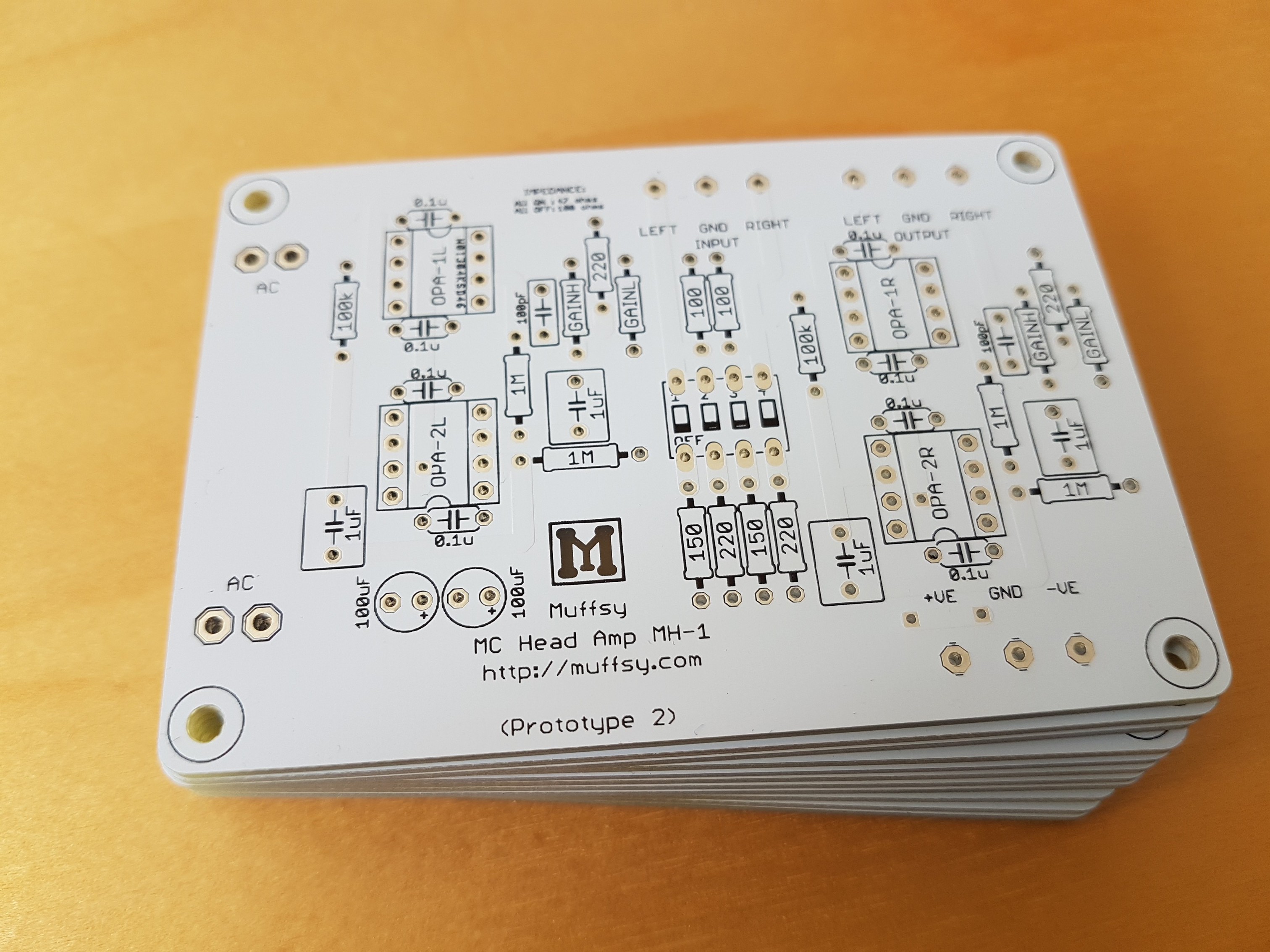
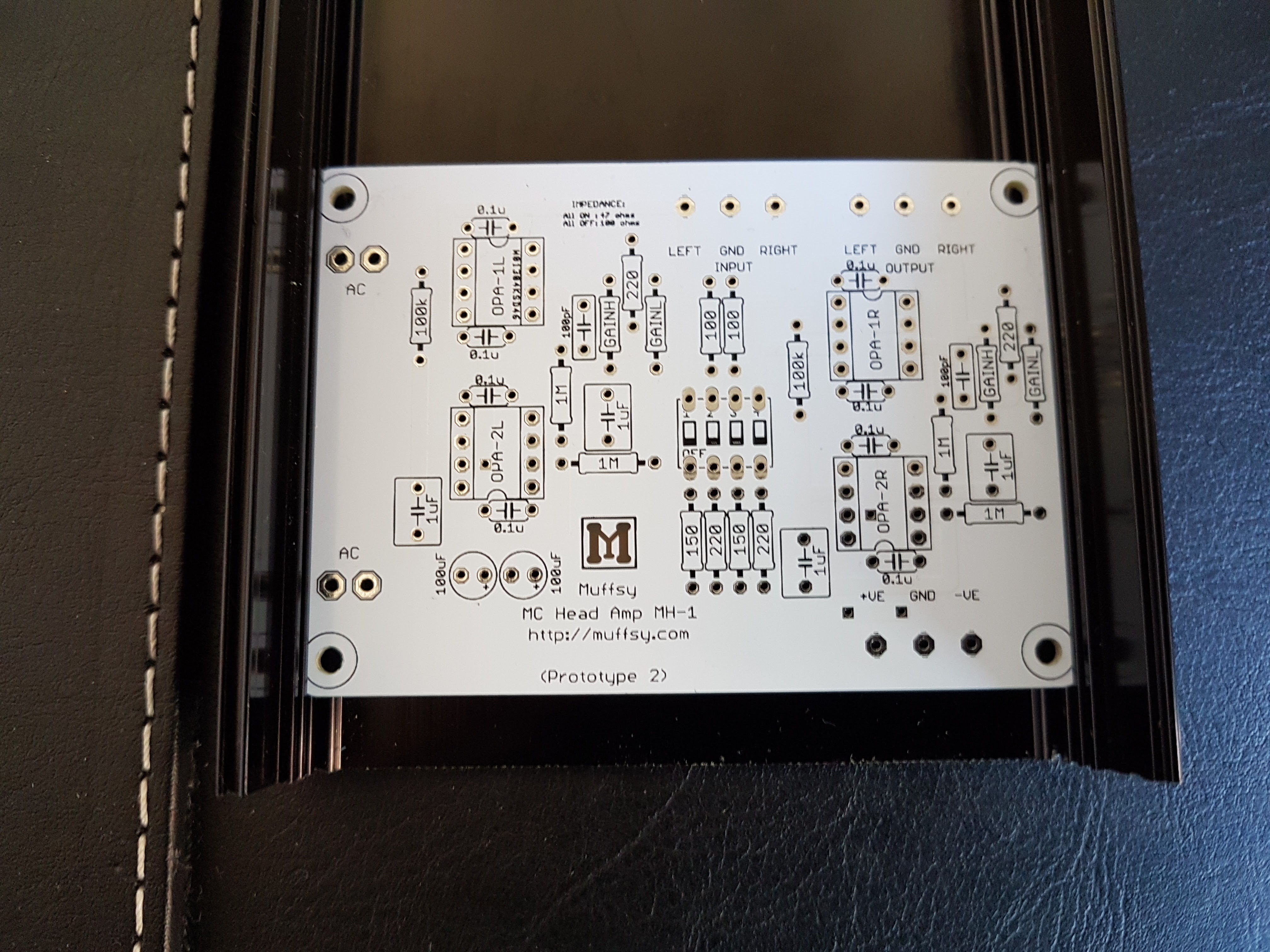
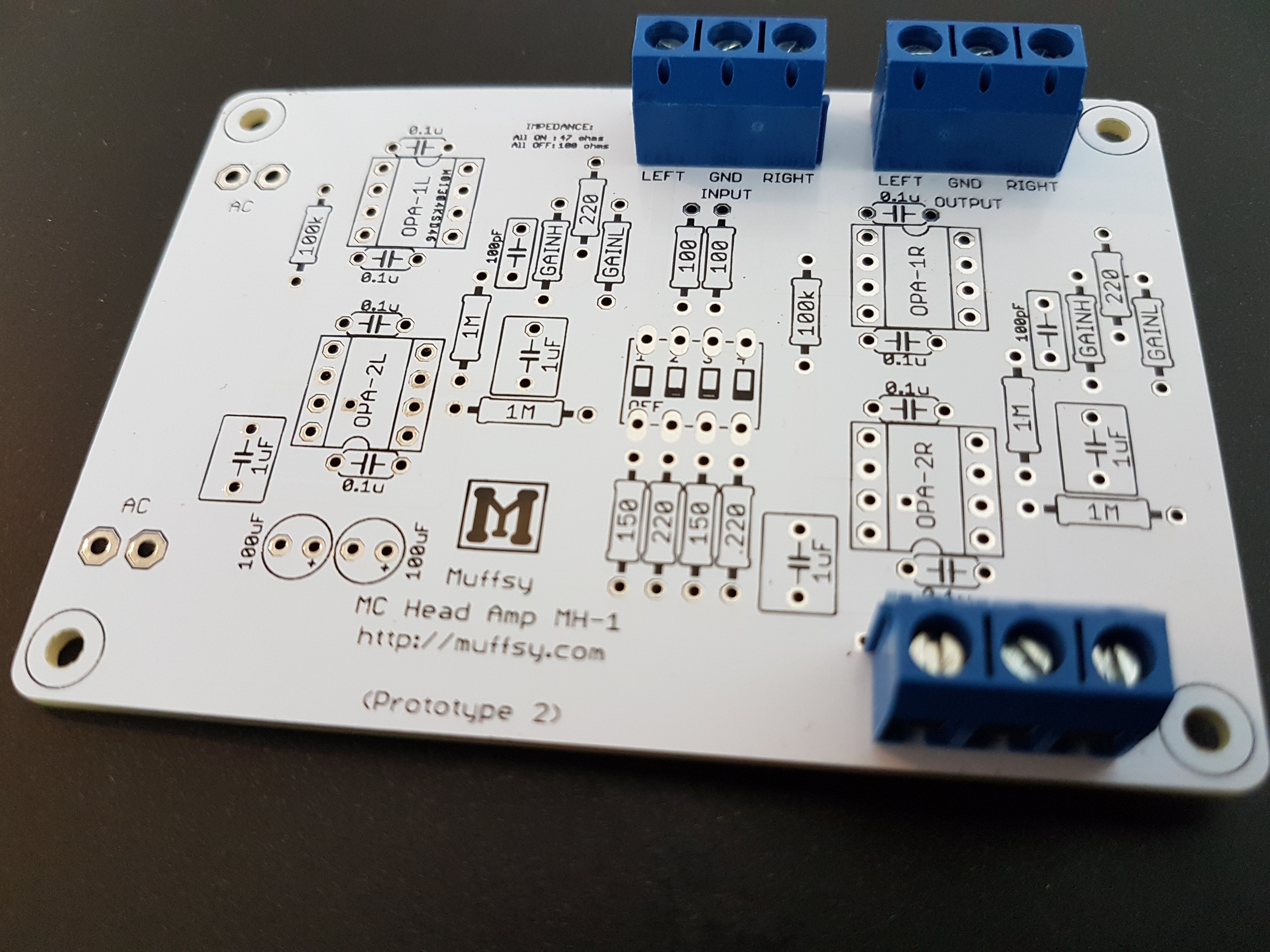
Prototype 2 - PCBs Received
07/20/2016 at 07:47 • 0 commentsThe boards arrived this morning:
![]()
It's time to solder on, test, and see how the board fits in the enclosure.
The AC pads on the left and the resistors on the right are a bit too close to the enclosure walls, there'll be some cosmetic changes in the next version.
![]()
Here's the board with screw terminals, just to get an idea of how it will look. The inputs/outputs are on the far side (close to the back panel) and the power connects on the near side (close to the power supply):
![]()
-
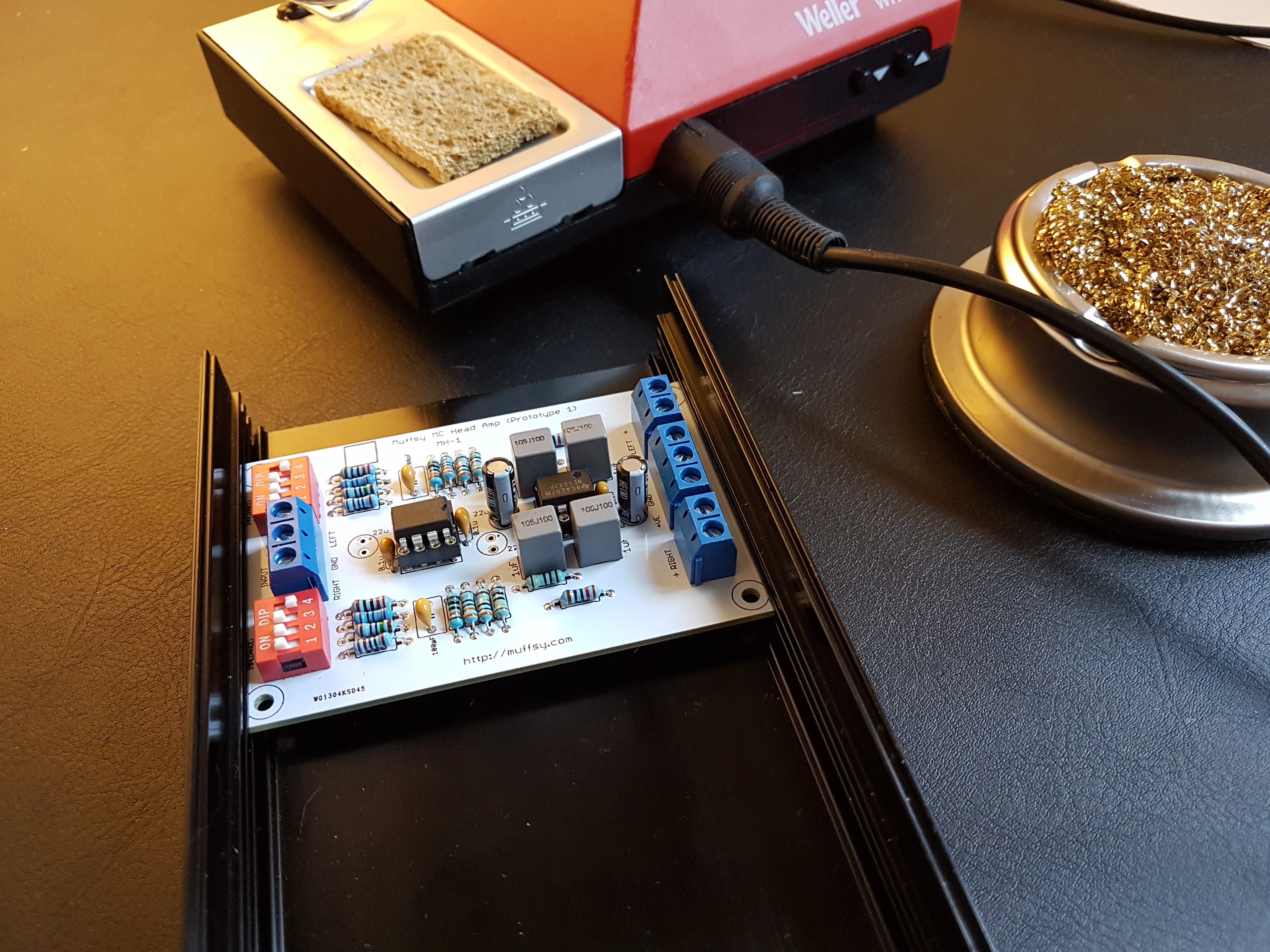
Prototype 1 - Built, First Measurements
07/13/2016 at 21:37 • 0 commentsHere is the Muffsy MC Head Amp - Prototype 1:
![]()
After testing different component values, including getting the op amp feedback capacitor wrong (creating a low pass filter with a cut off frequency of 480 Hz...), the circuit measures according to the calculations with an SNR just shy of 60 dB.
Some Prototype 2 boards have now been ordered and are expected to arrive in about a week.
![]()
-
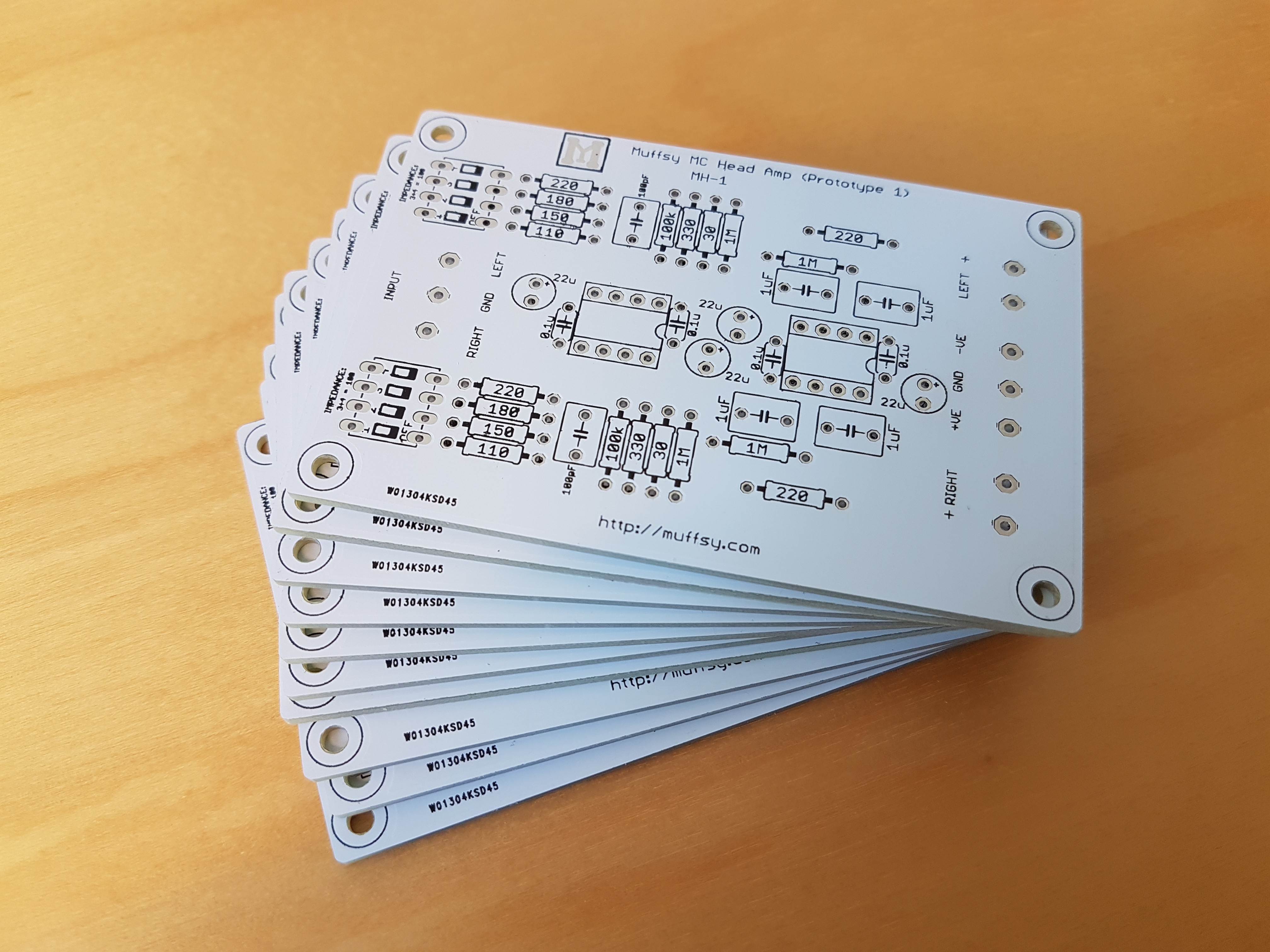
Prototype 1 - PCBs Received
07/11/2016 at 12:12 • 0 commentsHere they are!
Now, these won't be the final ones, there's another one in the process for that, but it will allow me to do some measurements and see if this project is feasible.
![]()
-
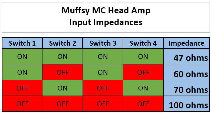
New Layout - Fewer Input Impedance Choices
07/11/2016 at 08:42 • 0 commentsWith the new layout, the number of input impedance choices went down. This is due to space constraints, so there will only be four impedance settings.
![]()
These options cover 47 and 100 ohms, plus a couple in between.
-
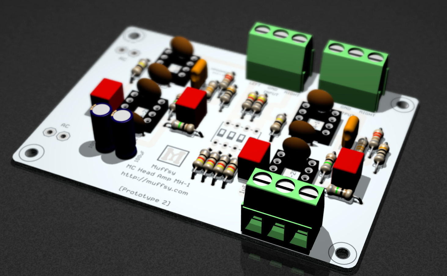
New Layout - Better Performance
07/08/2016 at 18:53 • 0 commentsTo get a signal to noise ratio of 70+ dB, single channel op amps are the only ones that offer noise levels low enough. Let's redo the layout, since the existing one uses dual channel op amps. Especially since the design with dual op amps has only ~60 dB SNR.
Hmm, running AC power cables over the input screw terminals for a minuscule MC signal? Not so great. Let's make some AC throughput tracks on the PCB.
While on the subject of input screw terminal, why not move it where the RCA connectors are. And why not move the output screw terminal to where the output RCA connectors are at the same time?
Since this is a complete redesign of the PCB, let's make sure the power screw terminal ends up where the power supply is.
This is a much better layout in terms of getting lower noise, better performance, less interference and easier construction.
Any negatives? The board is larger and it uses more components that also cost more. The input impedance settings went from 15 to 4 presets. That's still 400% more than you get from most others.
I still think this would be better, why settle for something that's "okay" just because it costs a handful of dollars less?
![]()
The first prototype cards (with the old layout) are expected to arrive in a few days, and they will let me do those first measurements.
Note that this layout is by no means final, it's more a proof of concept that shows it can be done in that restricted space. (Hey, I even got space over! This gave room for the AC power traces.)
![]()
UPDATE:
I consider this board to be a release candidate, and have ordered some PCBs for test. All the pictures on the project page, and the picture on this project log have been updated with the latest version.
Muffsy MC Head Amp
A DIY Dual Mono MC cartridge preamplifier for your record player

 The frequency response drops off to -3 dB at ~45 kHz. This seems to be a limitation of the QA400 which has a loopback frequency response of, you guessed it, 45 kHz. The -3 dB point as defined by the low pass filter in the gain network should be around 300 kHz.
 The value of the Intermodulation Distortion is of somewhat academic interest. In reality, the 1 kHz result will be way below the noise floor of the Muffsy Head Amp; I had to increase the input signal by almost 40 dB to even find it.