-
1Step 1
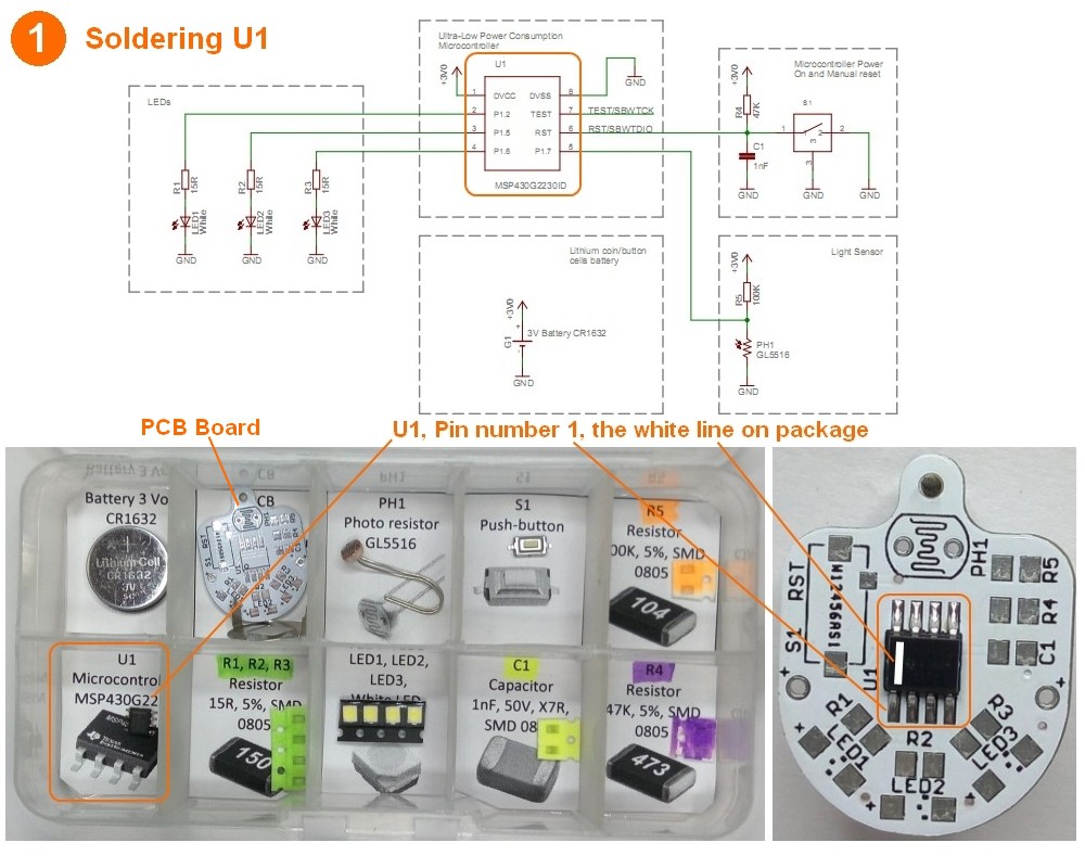
Step 1: Soldering ultra low power micro-controller MSP430 - U1
It is important to solder only in a well ventilated area.
Work areas must be kept free of static generating materials including styrofoam, vinyl, plastic, fabrics and so on.
Pay attention the white line of the U1 should be placed as showed in the Picture. U1 first pin should be close to R1.
![]()
-
2Step 2
-
3Step 3
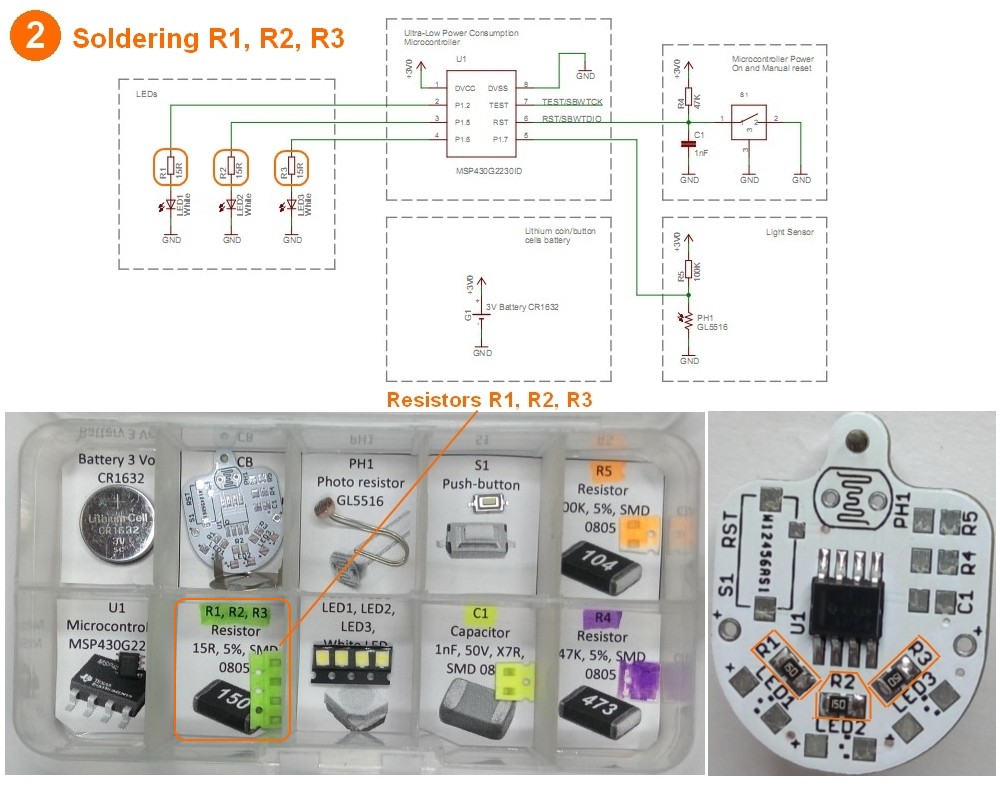
Step 3: Soldering White Light Emitting Diodes LED1, LED2, LED3
Pay attention to LED direction. The blunt (catted) angles of LEDs should be placed exactly as showed in picture.
The LEDs have a plastic package that that very sensitive to overheating.
Don’t overheat the LEDs.
![]()
-
4Step 4
-
5Step 5
-
6Step 6
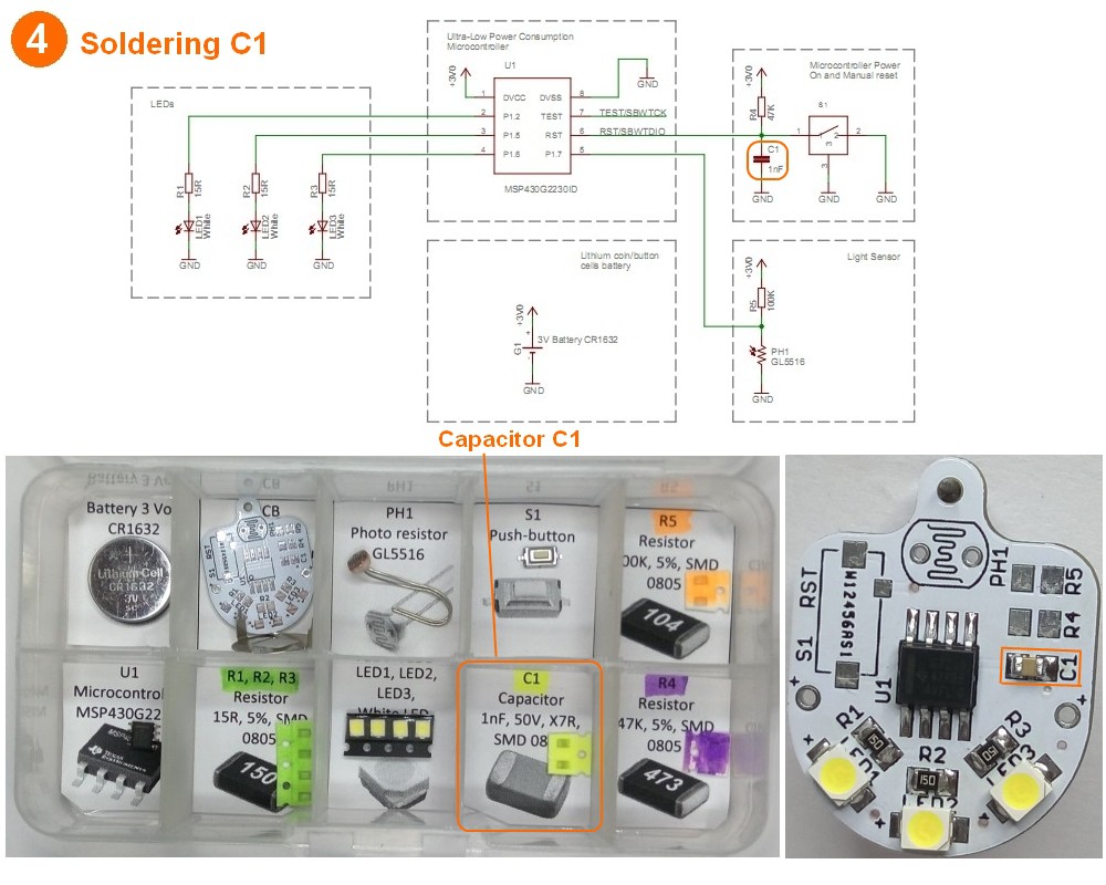
Step 6: Soldering resistor R5 of light sensing circuit
Soldering resistor R5 of light sensing circuit
![]()
-
7Step 7
-
8Step 8
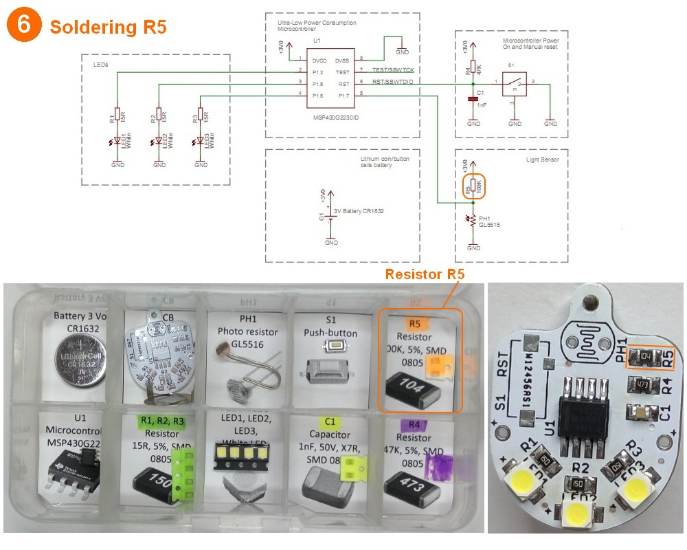
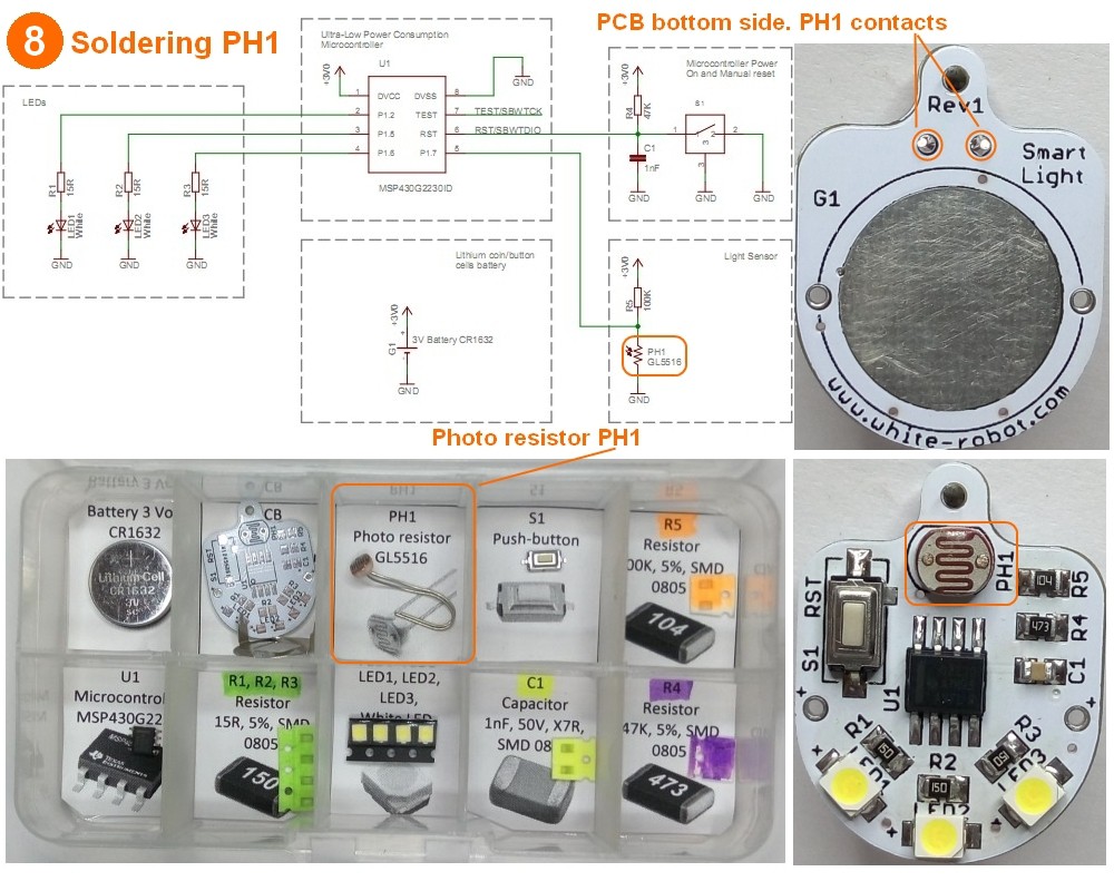
Step 8: Soldering light sensor photo resistor PH1
Soldering light sensor photo resistor PH1.
Clean the PCB contact pads by alcohol.
Put the photo-resistor PH1 to PCB.
Put a small amount of solder on one of the two legs of the PH1.
Put a small force down non the part and re-head the one pad to guarantee that the parts is flat against the PCB.
Solder thee other leg of PH1.
Cut of the rest of the PH1 legs by diagonal wire cutter.
![]()
-
9Step 9
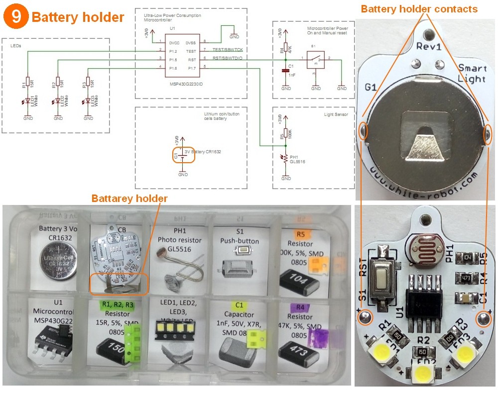
Step 9: Soldering flashlight battery holder
Clean the PCB contact pads by alcohol.
Put the battery holder to PCB.
Reference the picture for place battery holder with correct direction.
Put a small amount of solder on one of the two legs of the battery holder.
Put a small force down non the part and re-head the one pad to guarantee that the parts is flat against the PCB.
Solder thee other leg of battery holder.
![]()
-
10Step 10
Step 10: Insert the 3V battery into battery holder
The battery have positive and negative contacts.
Found the positive contact with (+).
See pictures.Insert the battery into battery holder.
The positive contact should be at battery holder side and the negative battery contact should be at PCB side.
When the battery will be inserted into flashlight the LED1 -LED3 should light up.
![]()
Light sensing LED flashlight
SMART LED FLASHLIGHT - a tiny personal emergency Light sensing LED flashlight, made from available components and very simple for replicate



Discussions
Become a Hackaday.io Member
Create an account to leave a comment. Already have an account? Log In.