-
1Step 1
-
2Step 2
Choose your PSU
Take a look at the data sheet (or description of the ebay item) of your leds. It will give you the forward voltage (Fv) of your leds.
Calculate the needed tension by adding the tension of the colors in your color pairs.
I chose to use Red-Green and Yellow-Blue pairs. With my leds this means (2.2+3.3) = 5.5V and (2.0+3.3) = 5.3V.
I need some PSU with a tension higher than that, so I can regulate intensity with resistors. I chose a 9V psu ($2 on ebay!), but if you have a 12V one (more standard), that will be ok too.
I will use six pairs of leds in my lamp. Each led is rated for 20mA, so I should need (6x20) = 120mA (pairs are in serie). But that would be too bright, I will probably feed at most 10mA to each pair, so 60mA is enough. Cheap wall adapter are now all able to deliver more than 120mA, so you don't worry about that if you do not want to use more than ten pairs.
-
3Step 3
Choose your color pairs
We will use one color for each nucleobase. Remember that nucleobases go in pairs, and that the only possible pairs are adenine-tymine and guanine-cytosine, so if you don't want your annoying bio-engineer friend to make sarcastic comments about your DNA Lamp, always use the same two pairs of different colors.
You can have either:
-mix of red-blue, blue-ed, yellow-green and green-yellow (I choose this one)
-mix of red-green, green-red, blue-yellow and yellow-blue
-mix of green-blue, blue-green, red-yellow and yellow-red
But you can't have:
-red-green and red-blue pairs
-red-red pairs
-
4Step 4
Find approximative values for the resistors
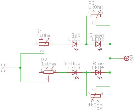
We will use two resistors. One (the series resistor) will limit the total current in the pair of leds, the other (the parallel resistor) will deviate part of the current to match the brightness of the brighter led to the brightness of the other.
We probably want more than 5mA in one of the leds. We probably want to deviate 1 to 10mA from the brighter led.
My pairs have about 4.5V voltage drop (5.3V at 20mA, but a bit lower at 5mA), and I use a 9V PSU, it means the tension for the potentiometer will be about (9-4.5) = 4.5V. With a 5mA current, you can use Ohm's law (U=R.I, so R=U/I) and find that you want at least (4.5/0.005) = 900 Ohm for the serie potentiometer. With 3.7V leds series and a 12V PSU, that would be 1660 Ohm. So let's just buy standard 1K or 2K potentiometers.
You probably want to deviate at least 1mA from the brighter led. Since the led will have a 3.5V (or less) voltage drop, Ohm's law again tell you that you want a 3.5kOhm potentiometer. In my case, I matched blue and green (very bright leds) with red and yellow (darker leds for same intensity). I know I will probably need to deviate at least 5mA and a 1kOhm potentiometer will be enough.
That's perfect, I hade five 1kOhm potentiometers, I used them.
-
5Step 5
Find precise values for the resistors
On your breadboard, make two circuits with:
-Two leds in series in each (your two color pairs),
-The serie potentiometers set to its maximal values in serie with the leds
-The parallel potentiometers set to its middle value in parallel with the brighter leds (that should be green and blue - if you use green-blue and yellow-red pairs you can start without the parallel potentiometer and plug it on the brighter led later)
-The power supply.
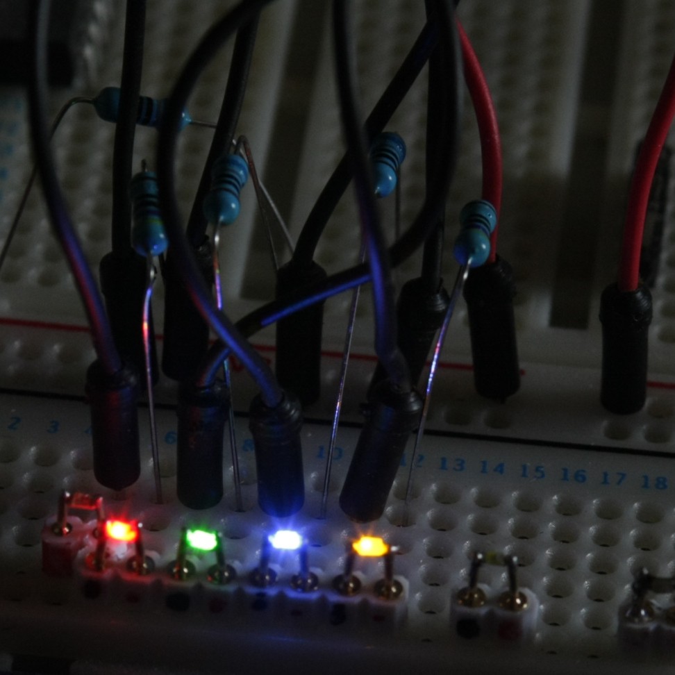
Then turn the potentiometers until you are pleased with the brightnesses. Remove the potentiometers and measure actual values with a multimeter.I found 556 and 720 Ohm for Red-Green, and 483 and 397 Ohms for Yellow-Blue (with my 9V psu)
Here is a picture of my result (a previous test I made not with potentiometers, but by manually replacing resistors!)
-
6Step 6
Choose your resistors
The series resistor will be made, in the end, with three SMD resistors. The value of their sum must be as close as possible to the one you measured on the series potentiometer.
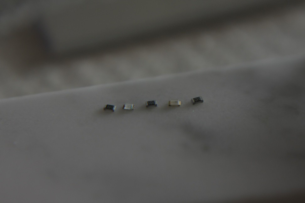
In my case, for 556 Ohm, I could find a 330, a 200 and a 20 Ohm SMD resistor in the set I bought, the sum is 550, ok.
For the parallel resistor, you will take the closer value you have. (for 720, I tried both 510 and 820 Ohm)
-
7Step 7
Lay the components
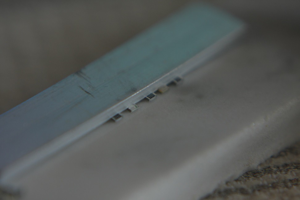
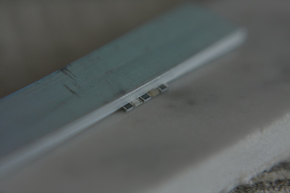
Take something that is flat, heat resistant, on which solder won't stick (I used some piece of marble, left-over from a bathroom floor)
Lay the component with the side you want the more visible upside (I choose black side of the leds and light emitting side of the LEDs). Be sure to have the two leds in the same direction, and to alternate 1 resistor, 1 led, 1 resistor, 1 led, 1 resistor.
Push them gently with something flat so they are perfectly aligned
Push them with tweezers so the borders of the components touch each other, but components do not overlap
Repeat the two previous steps until you are pleased with your result
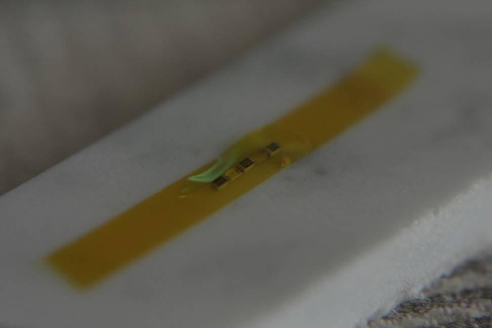
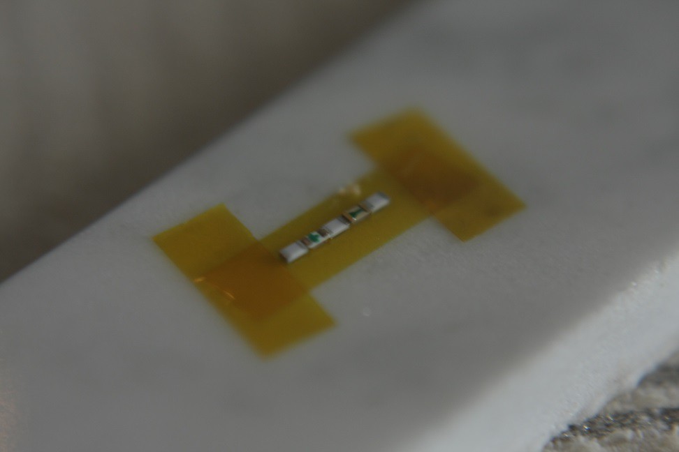
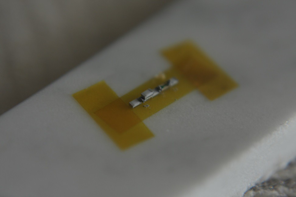
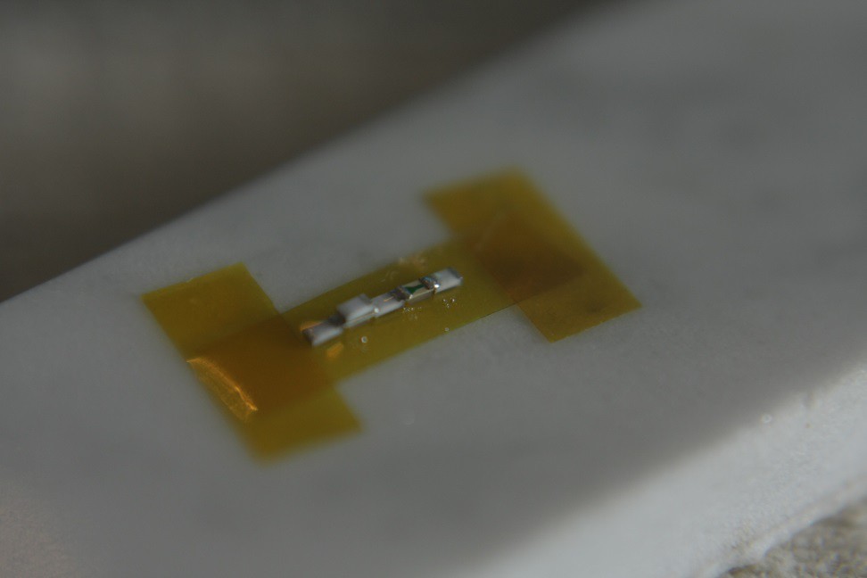
Put some polyimide adhesive tape on top of the components (don't make them move!)
Flip the tape so the components are upside down, and secure the tape with some other tape.
Use you digital multi-meter on "diode test" position and test the diodes: they will light gently and you can make sure they are in proper direction and color
-
8Step 8
Add solder paste
Don't add to much, you want to avoid solder bridges and ugly solders. But you want the solder to be strong enough, so don't use too few :)
You can use a needle, a toothpick... You can't use a baseball bat, it is not precise enough.
On the bright led, where you will add the parallel resistor, you want a bit more solder.
-
10Step 10
Solder
Use a reflow oven, a hot air soldering station... You can try cheap hot air gun or maybe a soldering iron but I tested only the oven and rework station...
With my solder paste (the cheapest one on dx.com), a good setting on my reflow station is 240°C, minimum flow, smallest nozzle.
The parallel resistor may move when the paste melt on one size. If this happens, just continue heating and use tweezers to reset it.
Before removing the component from the tape, test the assembly with your PSU. If the brighter led does not light, you probably have a solder bridge (redo from scratch with new components, that's faster than trying to solve the problem). If the brighter led is too bright, the solder probably does not touch one side or the parallel resistor, add a bit more paste and re-apply heat.
 ftregan

Discussions
Become a Hackaday.io Member
Create an account to leave a comment. Already have an account? Log In.