-
Observations and issues with first prototype hardware design
08/17/2016 at 00:21 • 3 commentsOnce my initial prototype board was assembled I was faced with everyone's favorite task - bug fixing! There were some problems that became evident right away, and others that took an embarassingly long amount of time to identify and fix.
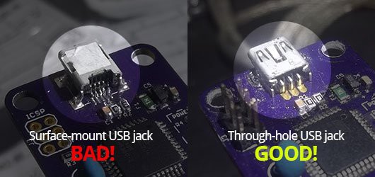
- Surface-mount USB mini-B connectors are HARD to solder!
The first problem I found was that in reality, SMD USB connectors are extremely hard to hand solder without a hot-air rework station! I gave it a good shot, but I quickly realized that it was going to be way more difficult than it should be to manuever my soldering iron in the constrained space aroudn the connector's pins.
Solution: for the prototypes and DIY-able version of this device, I should definitely stick with through-hole connectors so that more people can assemble and maintain their boards.
- Instrumentation amp didn't get connected to GND
Once I was able to burn the Arduino Leonardo bootloader onto the ATMega32u4 and upload a basic sketch for testing I found that I wasn't getting any readings from the pressure sensor.. This was a bit frustrating to troubleshoot because it made me question just about every step of the process up to this point. Was the board design flawed? Are there defects in the board from fabbing? Is the bootloader or microcontroller somehow corrupted? Do I suck at programming more than I thought I did?
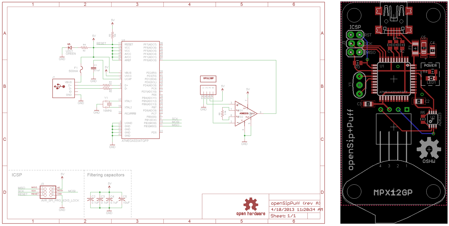
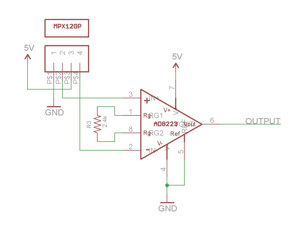
Eventually I found that this was indeed a hardware problem and traced the cause down to the instrumentation amplifier. Either out of haste or inexperience, I neglected to connect the amplifier's reference pin to the ground plane, effectively preventing it from receiving power.
Solution: I soldered a jumper wire from the reference pin to a known ground connection, and readings started coming in right away! I also updated the Eagle board design straight away to prevent future boards from having the same problem.
. - MPX12GP sensor connection is unreliable
When I initially specced out the MPX12GP it looked like it would be easy to interface with. It has long 0.1" pins which seems like they'd mate well with 0.1" female headers, allowing the sensor to be easily replaceable by users. In practice, though, this didn't work out so well for a few reasons:
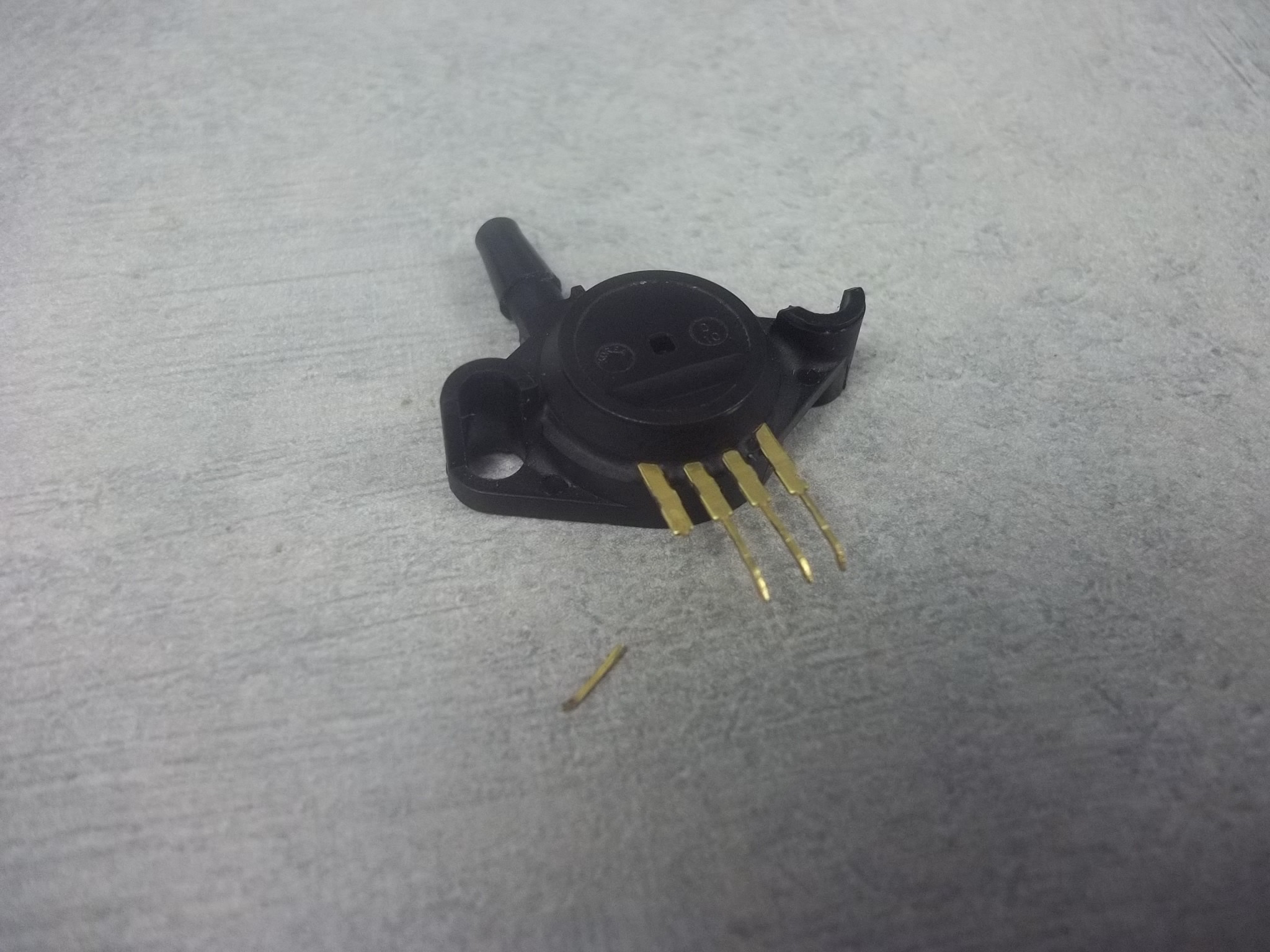
Firstly, the pins are actually a bit on the slim side, making them a little loose in the female header sockets. Not ideal for real-world usage.
Secondly, because of how thin the pins are they break very easily at the slightest amount of torque or bending.
Thirdly, the sensor is thick enough that the pins are elevated a bit too much when the part is mounted flat onto a board. This means that the typical right-angle female headers that I had in mind do not line up with these pins, making the fit even more sketchy than when they are aligned.. I considered using extra-long right-angle female headers, but they are hard to find (and therefore not cost-effective) and would not solve the other two problems with the sensor.
Solution: given the strange mounting that would be required, and the build quality of the pins, I think the best thing to do is to find another sensor. I believe I have actually found one, just need to test it out!
- Surface-mount USB mini-B connectors are HARD to solder!
-
First prototype PCB design, fabrication and assembly
08/07/2016 at 15:33 • 0 commentsBased on the results of my breadboard prototype I knew that my concept was solid and that the parts that I had chosen would give me the results I was looking for. In particular I knew that the pressure sensor worked great and that my instrumentation amplifier worked as intended to make the sensor's analog output "loud" enough for the Arduino ADC to read.
For me the next logical step was to translate my design into a circuit board that I could have fabricated. I used Eagle CAD for this, and whipped up a custom footprint for the pressure sensor.
Note: This is just the initial prototype design, and I have already made newer ones that I will upload and document in upcoming build logs! Just posting it here to share my process.

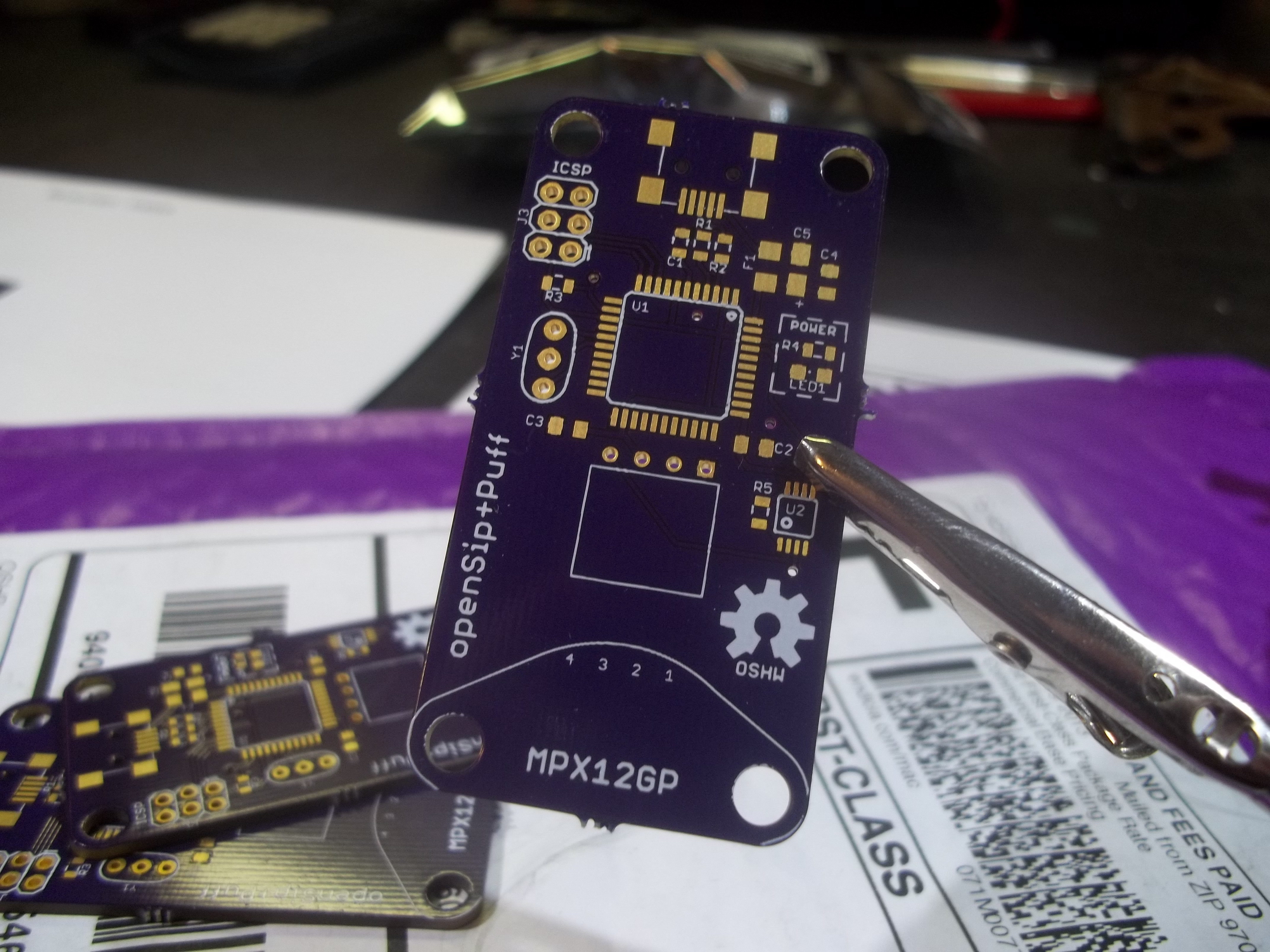
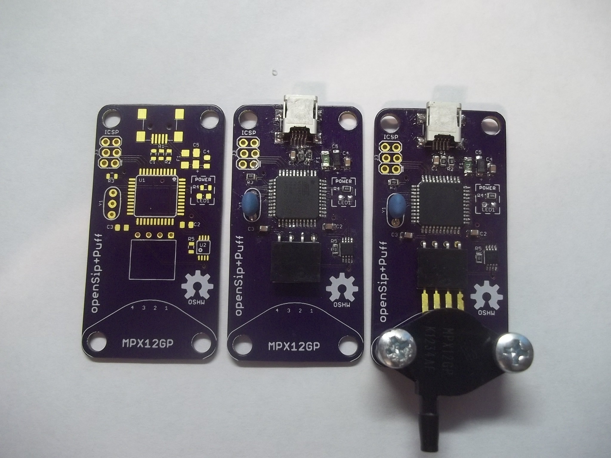
I sent my board design off to OSHPark and ordered my parts from Digikey so that when the boards arrived I could get them assembled right away. Just a couple weeks later I received this package of 3 boards, all for a very reasonable $13.71!

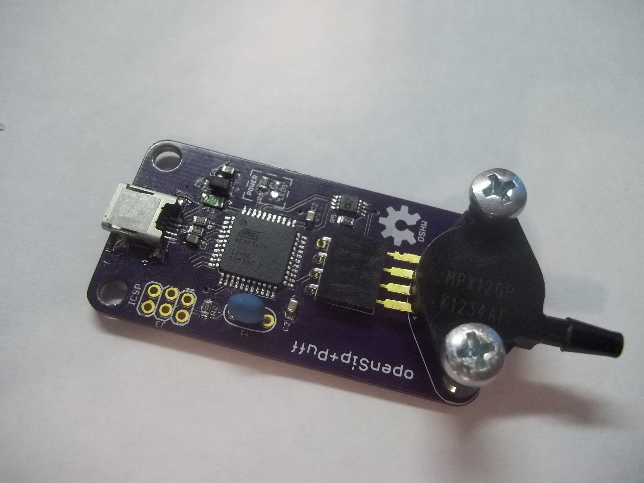
I went ahead and soldered all the parts to the board and ended up with a pretty sweet looking prototype!
With the hardware assembled the next thing to do is to burn the Arduino Leonardo bootloader onto the ATmega32U4 and start experimenting with firmware sketches.
-
Original breadboard prototype
08/06/2016 at 20:55 • 0 commentsWhen I first started this project in early 2013 I knew there were two main components at the heart of this system: the ATmega32U4 microcontroller and some sort of pressure sensor that I could attach a vinyl tube to.
Through lots of googling and small insights gleaned from obscure forum posts, failed projects and random comments on other air pressure-based projects I eventually stumbled upon the MPX12GP pressure transducer from Freescale.
I saw that it's output voltage was only between about 0-55mV (proportional to the air pressure on the sensor), which is below what the ATmega32U4 ADC can reliably read, so I needed a way to amplify the signal to be "loud" enough that the microcontroller could read it.
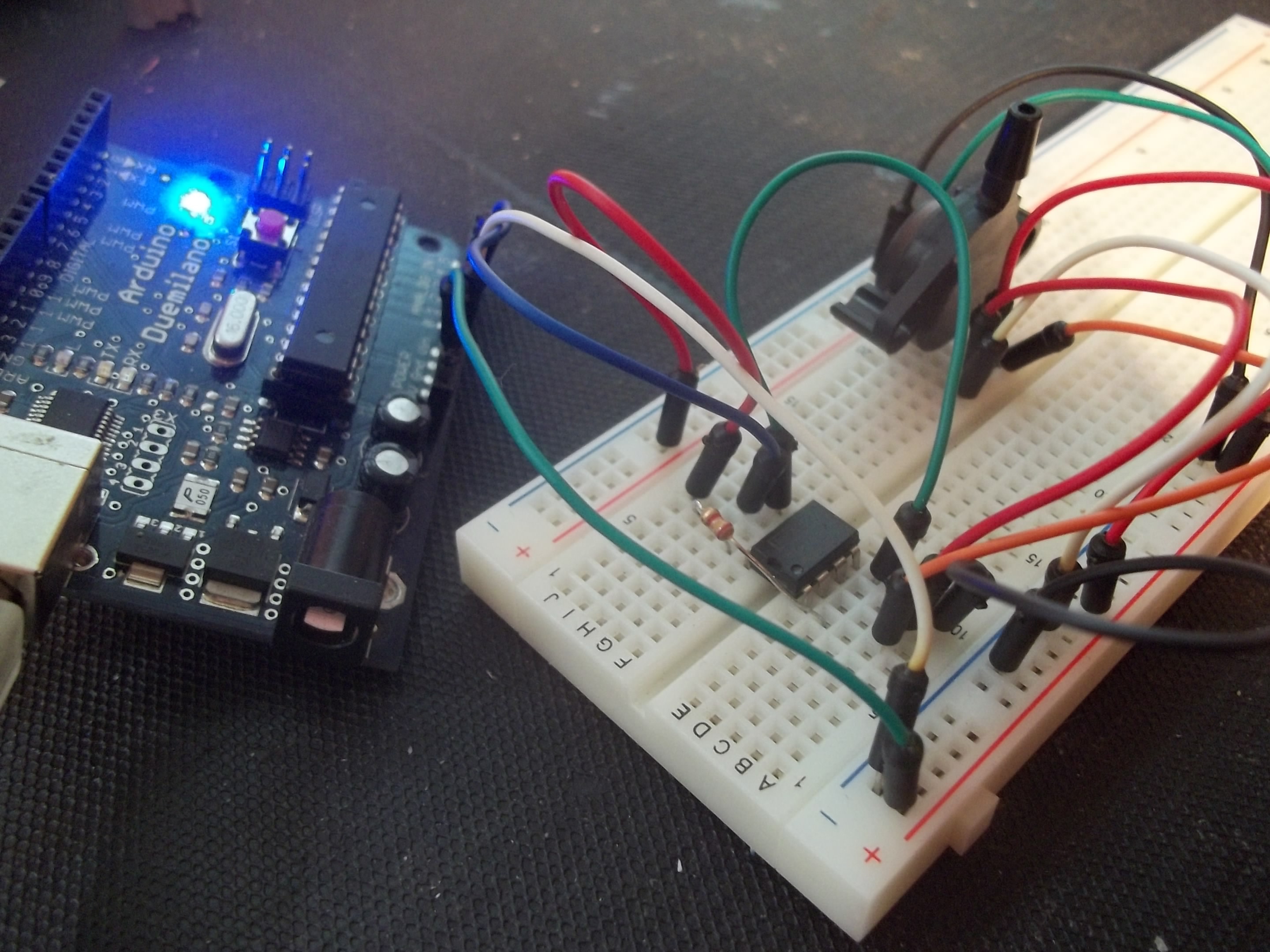
To do this I used an instrumentation amplifier (the breadboard-friendly INA122) tuned to transform the tiny voltage (0-55mV) to be more in the range of 0-5V so that the built-in ADC could figure out air pressure based on the voltage read at the appropriate analog input pin.
I assembled my circuit on a breadboard and hooked up the output of the instrumentation amplifier to an Arduino's analog input pin, which was programmed to simply take a reading on the pin and send that value to my computer over serial.
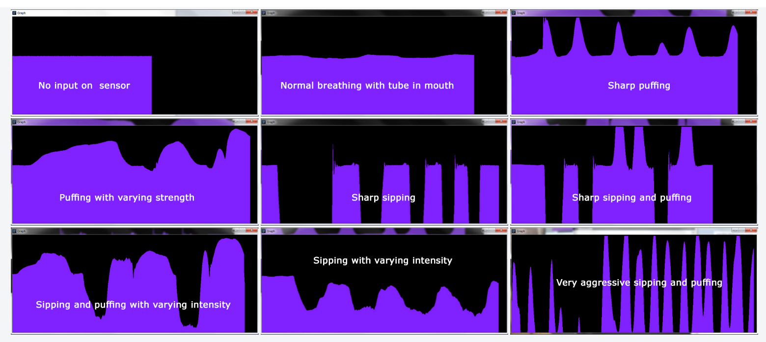
I then put together a little sketch in Processing that plotted the values coming in from the serial connection onto a rolling graph allowing me to visualize the output of the sensor in real-time. I think the new Arduino IDE includes a serial graphing tool, but at the time I had to do it the "hard" way!
What I found right away was that when there is no input on the sensor the output voltage hangs at around 1/2VCC, which in this case would be around 2.5V. By blowing air into the sensor (i.e. a "puff" or positive air pressure) the voltage went up in proportion to how hard I blew. Sipping on the tube (i.e. negative air pressure) made the voltage go down.
For me this was a very successful experiment and motivated me to stop thinking about just simple keypresses and mouse clicks and start thinking about more creative and expressive uses for this system. The stability of the signal and the ease of varying the intensity of your sips and puffs really blew me away, so I knew I had to do some weird stuff in the future!
Given how well the tests went I felt there were two obvious next steps: building out more robust firmware and putting together a prototype PCB. Both of which I will discuss more in future build logs!
openSip+Puff
Low-cost, open-source "sip-and-puff" interface to enable new methods of expression for people with and without limited mobility.
 Jason Webb