agp.cooper
-
Schematic Error
12/05/2016 at 23:36 • 0 commentsSchematic Error
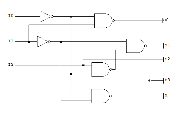
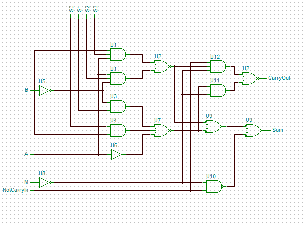
Seems as though I mixed up the truth table when I designed the 181 ALU decoder. The schematic should be:
![]()
regards AlanX
-
ALU III Revision
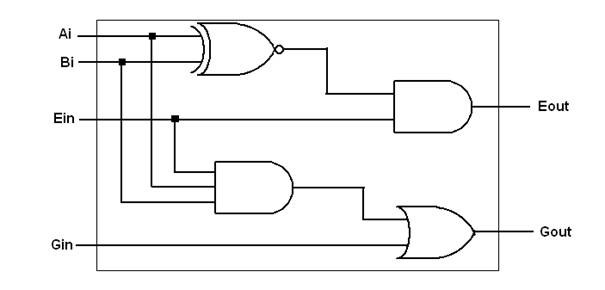
08/14/2016 at 09:02 • 4 commentsI was trying to test the ALU design presented previously when I realized something was wrong with the comparator. Now where did that design come from? I could not find it on the Internet (surprising) but this one looked good to me:
![]()
(source: http://fpgacenter.com/digit_dsgn/log_gates/comparator.php)
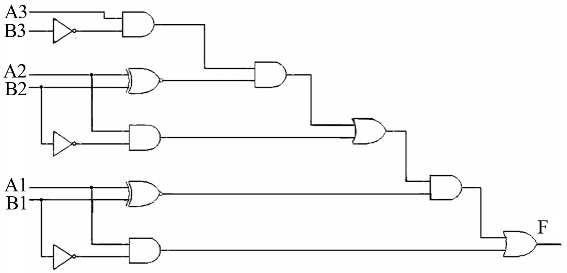
Anyway, not happy where did it come from? Eventually I found this:
![]()
(source: http://file.scirp.org/Html/2-7600304_41935.htm)
Which I recognised I had used as a base. This came from:
"Design of Low Power Comparator Using DG Gate" by Bahram Dehghan, Abdolreza Roozbeh and Jafar Zare.
This is a A>B comparator only.
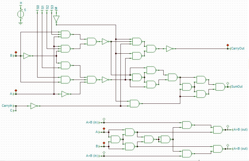
So stripped out the bits I needed, converted to NAND gates and realized I could "mirror the circuit for A<B and reproduced my original circuit less the design error I had carried over. This time I did not to piggy-back off the ALU gates (so the comparator is now stand alone):
![]()
The Hazards of Teaching Yourself
In the above circuit I have some logic signal flags. Now I have had Tina Pro V5.5 for 10 years and did not know I could do this (the documentation is pretty bad). I have almost exclusively used Transient Analysis even for digital design. Now I am sure that if I did do a course then this feature would have been explained. (Note: I don't work in the electronics field. I was a mining engineer and we like to dig holes in the ground.)
Because Tina Pro 5.5 is pretty unstable I migrated to the Tina-TI version (and that does not have logic signal flags). I was only using Tina Pro 5.5 because I needed something better than Transient Analysis. If I went back then I would have to re-digitize most of my current work as Tina-TI does not export the really old file formats.
Crippled Software
I have looked at Tina 10 but the hobby versions are crippled for only small circuits and the unlimited version are crippling in price.
I have an old version of Cut2D (for CNC) that works really well and is unlimited. Cost about US$180 from memory a few years ago. The latest versions have gone the same way, crippled in capacity or crippling in price. Go figure! It not that there are no substitutes.
AlanX
-
DIY ALU III
08/13/2016 at 14:00 • 0 commentsDIY ALU III
Well I can't leave it alone! I decided to have a closer look at the 74181, so I extract a bit-slice from the schematic (the comparator logic is lost):
![]()
Not hard, even found a schematic error - I wonder if anyone else has found it as well?
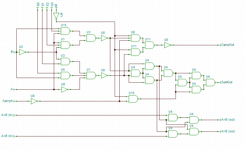
I then converted the gates to NANDs, and added in my preferred comparator logic. Here is the result:
![]()
So now I am down to 1 inverter for the Carry In (don't like the Not Carry logic of the 74181) and 27 gates per bit-slice. The main difference with my version is it will be slower to propagate.
So the total gates for the 74181 was 100 and my version is 109 (but includes a better comparator logic). Add six gates for the Selection Decoder (refer to the 4 Bit CPU ALU issues) and I get 115 gates.
This design would equate to seven packages per bit slice (much better!).
I case you have forgotten why I an not using XOR gates or MSI logic, this work is in preparation for a possible transistor CPU, so it uses SSI NAND gates.
I will have to look at the selection logic to see if I can fix it (another post?) or merge the Selection Decoder.
AlanX
-
DIY ALU II
08/13/2016 at 10:02 • 0 commentsDIY ALU II
I had a play with Logic Friday investigating a DIY ALU that matched the 8 functions selected for the 4 Bit CPU II.
For reference the 74181 has 100 NAND gate equivalents (by my count).
I coded a 1 bit ALU for:
In(A), In(B), In(Carry), In(A>B), In(A<B), S0, S1, S2 -> Out(C), Out(Carry), Out(A>B), Out(A<B
Where for S0-2:
- A ADD B
- A ADD !B (i.e. A MINUS B MINUS 1)
- OR
- AND
- XOR
- B
- !B
- A
The result was:
- 29 "prime implicants" (i.e. boolean equations)
That translates to 37 NAND gates (with as many inputs as necessary).
(The 37 equates to 8 inputs, 4 outputs and 29 prime implicants or PIs.)
Therefore scaling up my ALU would result in 148 gates. Not unexpected as my ALU has no useless functions.
Some experimentation (functions and function order) may reduce the PIs a little.
Logic Friday also can produce a rationalise schematic based on standard packages, suggesting:
- 2x Hex Inverter
- 8x Quad 2-Input NAND
- 4x Triple 3-Input NAND
- 1x Dual 4-Input NAND
So I will need 60 packages for my 4 bit DIY ALU! Perhaps I should just "close my eyes" and get to like the 74181!
Or I could just copy the 74181 design and add my "pre-selector code" for 106 NAND gates (about 30 packages).
No real headache using four 256x4 PROMs or a small PLA chip.
AlanX
-
DIY ALU
08/12/2016 at 03:56 • 0 commentsA SSI ALU for my bit-slice CPU
There is not much on the Internet about DIY ALUs if you don't like the 74LS181.
For my Weird CPU I used an adder (74LS83A), a comparator (74LS85) and the NAND function (74LS00). I should have included the XOR and SHR functions as they were expensive to implement in software.
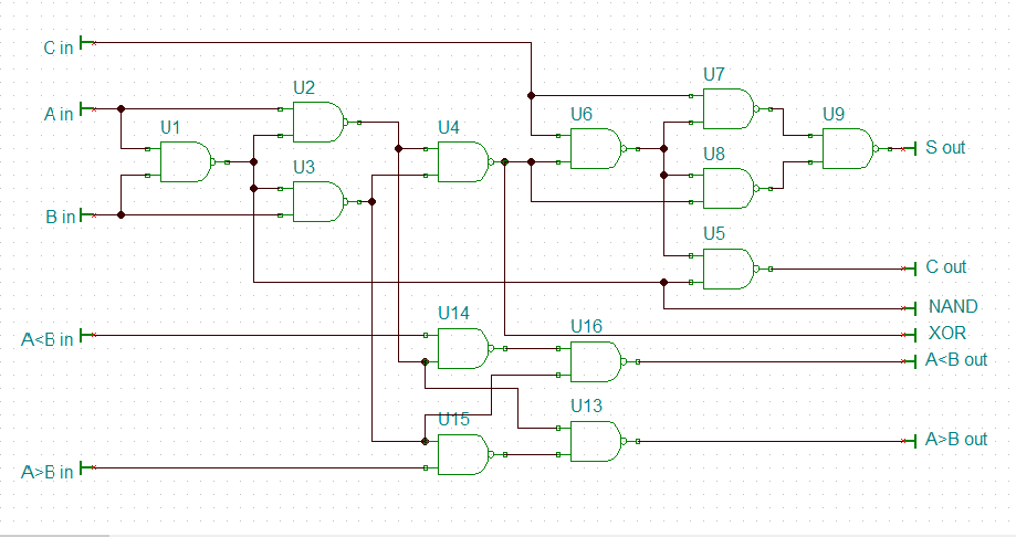
Here is the schematic from my Bit-Slice SSI CPU (it is on hold at the moment):
![]()
So you should recognise the NAND gate equilavent of an XOR gate (U1-4 and U6-9) that make up an adder (with U5). The remaining gates (U13-16) make up a comparator. I have also picked off the NAND and XOR outputs.
Other than SHR it is all you really need for a DIY ALU. The rest is efficiently implemented in software.
AlanX