Close
0%
0%

4014 LED minimodule

A cheap, small module that displays two 7-segments digits with simple multiplexing

Similar projects worth following
This is a fork originating from https://hackaday.io/project/8693-dypled/log/43833-another-module

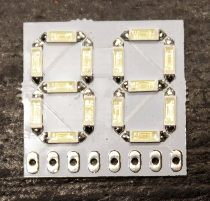
This module is small PCB for digital display of numbers, using the 4014 LED format for the segments.
Cheap, simple, very low profile, easy to drive, can be assembled to make large numbers.
Initially meant to prototype the DYPLED.com design but useful and modular for other projects as well !

Version 1 has a blunder, depending on the model of LED because some models have reverse diodes.
V2 has another tiny blunder, that is solved by v2.1

20160816:

@Dylan C. asked me to contribute to the #DYPLED project. It's already pretty finished, quite sophisticated (overkill ?) and still requires non-trivial tools. But yesterday I made this quick PCB to help prototype the next revision of the board with the single-rail multiplexing method... So let's fork it !


Some specs:

From the users' perspective, the module is a very thin PCB (0.4mm, 0.6mm, max. 0.8mm PCB) to ease integration in other projects ( #Discrete YASEP is the project that needs this).

Visual comfort is important :

  • high frequency multiplexing is easier on the eye (I found that 6KHz was a good frequency) but it depends on the application
  • white background to reduce fatigue
  • warm white LED is kinder than cold white
  • no visually-distracting feature on the user-visible side (no via, parts etc.)
  • even dimensions (8×0.1" or 20.32mm) to ease placement of multiple modules on a standard 0.1" grid (and the digits look regular)

There are 14 white LEDs, driven as 7 back-to-back pairs by a 3.3V digital signal (the integrated protection diodes limit the current, it's for display purpose, not lighting). The user must care about the multiplexing and dimming, to adjust the contrast.

Multiplexing is provided by one common rail/signal. Let it float if you blank the display, drive to 3.3V to turn one half of the LEDs on, drive to 0V to drive the other half. The tiny gotcha is: don't forget to negate the active logical values when driving to 3.3V, or else the pattern will be reversed.

Floating the rail (set the corresponding I/O to "high impedance") allows multiplexing several board, if you want to display 4, 6 or 8 digits instead of just 2. Just drive the individual common rails with a respective 3-states capable I/O pin to select which display to drive at a given time.

Note: If you drive the segments with more than 3.3V, you have to add series resistors with an appropriate value (left as an experimental exercise to the user).


Important !

Depending on the maker and model of LED, the 4014 format might embed a protection diode. This changes the multiplexing topology and there are 2 revisions of the board:

Version 0/1: No protection diode,
 parallel connection and resistor

                   |---|<|---|
                   |         |
Data ----\/\/\/----+         +--- Mux rail
                   |         |
                   |---|>|---|

Version 2: protection diodes
  serial connection, no resistor

Data ------|>|-----|<|----- Mux rail

Logs:
1. Damned protection diodes...
2. Version 2.0
3. Rev.1 PCB arrived
4. There are two types of 4014 LEDs !
5. a prototype (@al1)
6. First working units
7. Contrast enhancement with a diffusion layer
8. a second prototype - and some bugs (by al1)
9. Team work on HaD
10. My first v2 boards
11. Settling for Zener-less LEDs
12. New batch
.

Module4014_v2.1.brd

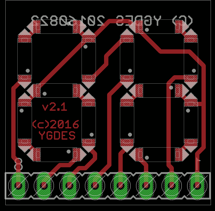
Eagle v5.7 Board file for v2.1. (for LEDs with reverse protection diodes) @al1 found a blunder in rev2.0 (one reverse LED), this is corrected here

brd - 27.35 kB - 09/13/2016 at 23:07

Download

VID_20160906_191939.3gp

Demo video of the first 3 working units (rev0)

3gpp - 4.59 MB - 09/06/2016 at 18:53

Download

4014_LED_mini.hex

HEX file of al1's AVR test program for rev0. For ATmega328P (Arduino Nano D2-D8 segments D9 common pin, just plug your 4014 model next to Arduino nano on breadboard)

hex - 3.75 kB - 09/06/2016 at 16:01

Download

4014LED.c

al1's AVR test program for rev0. (With little changes also for rev2)

x-csrc - 7.57 kB - 09/06/2016 at 16:00

Download

main.c

al1's AVR test program for rev0. (With little changes also for rev2)

x-csrc - 1.81 kB - 09/06/2016 at 16:00

Download

View all 8 files

  • 1 × PCB
  • 2 × 1206 Resistor network, 4×1K Ohms
  • 14 × 4014 format LED, warm white (beware of the integrated protection diodes)

  • New batch

    Yann Guidon / YGDES08/01/2018 at 03:17 0 comments

    Thanks to the HAD prize seed fund, I could afford more PCB !

    I ordered more #DYPLED boards in .8mm thickness and white soldermask. And this time I successfully "tented" my vias, which greatly helps with assembly :-)

    As previously written, I used Zener-less LEDs. This is clearly indicated in the marks at the back of the module. I'll have to solder a few... Overall, I could solder 44 modules, more than I can use now, so who is interested to get/use some ? Should I open a Tindie store ? :-)

  • Settling for Zener-less LEDs

    Yann Guidon / YGDES11/17/2016 at 16:08 14 comments

    This project was on hold for a while, for various reasons, but I am resuming it (along with #DYPLED) thanks to the delivery of a new batch of warm white LEDs. I just tested them and they have no Zener or protection diode (like the previous warm white batch). It seems the cold white LEDs have the Zener, despite coming from the same seller.

    This means that I don't intent do waste time on the Zener'ed LEDs (at least for digit display purposes). I'll stick to version 1 with series resistors and parallel connexion.

    Time to order more PCBs...

  • My first v2 boards

    Yann Guidon / YGDES09/15/2016 at 02:19 0 comments

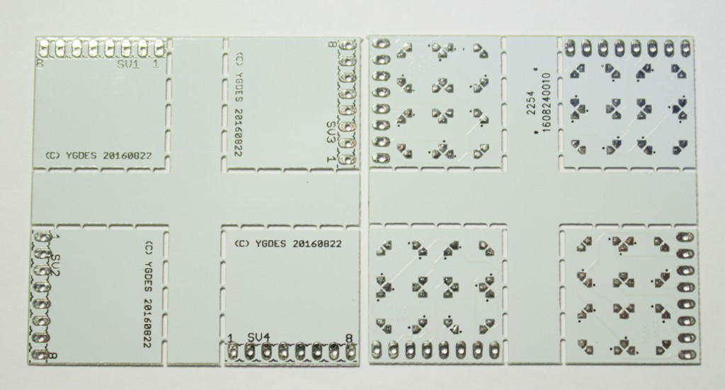
    The DirtyPCBs package is here and the boards are just as expected.

    The experience gained with the previous runs has been useful, look at my page describing the tiny differences between DirtyPCBs and DangerousPrototypes: Dangerous Prototypes vs DirtyPCB : same maker, different process

    In this case : no via, so no tented via problem, the milling has not been modified (much better for soldering the LEDs while still attached), the serial number marking is manually located in a blank place (thanks !)

    The only defect is the one found yesterday by @al1 (see a second prototype - and some bugs (by al1))and it's just a matter of reversing F1.

    Note: this board is good only for LEDs WITH an internal reverse diode.

    Time to solder a few now...

    Between the v1 and v2 boards, I must have enough digits to prototype a first #Discrete YASEP ;-) Which will I choose ? v2 is great because there is less wiring (easier routing) and no series resistor but the matching LEDs I have are cold white, and warm white goes to v1 boards...

    If you are interested to get some of these boards, send me a message !

  • Team work on HaD

    Yann Guidon / YGDES09/13/2016 at 23:14 0 comments

    @al1 found a stupid error I made in the v2.0 so I reversed the segment F1 on the new v2.1.

    I uploaded the new .brd as well.

    It won't go in production before a while. Meanwhile, the precedent versions can be coerced into working :-)

  • a second prototype - and some bugs (by al1)

    Alex09/13/2016 at 16:28 2 comments

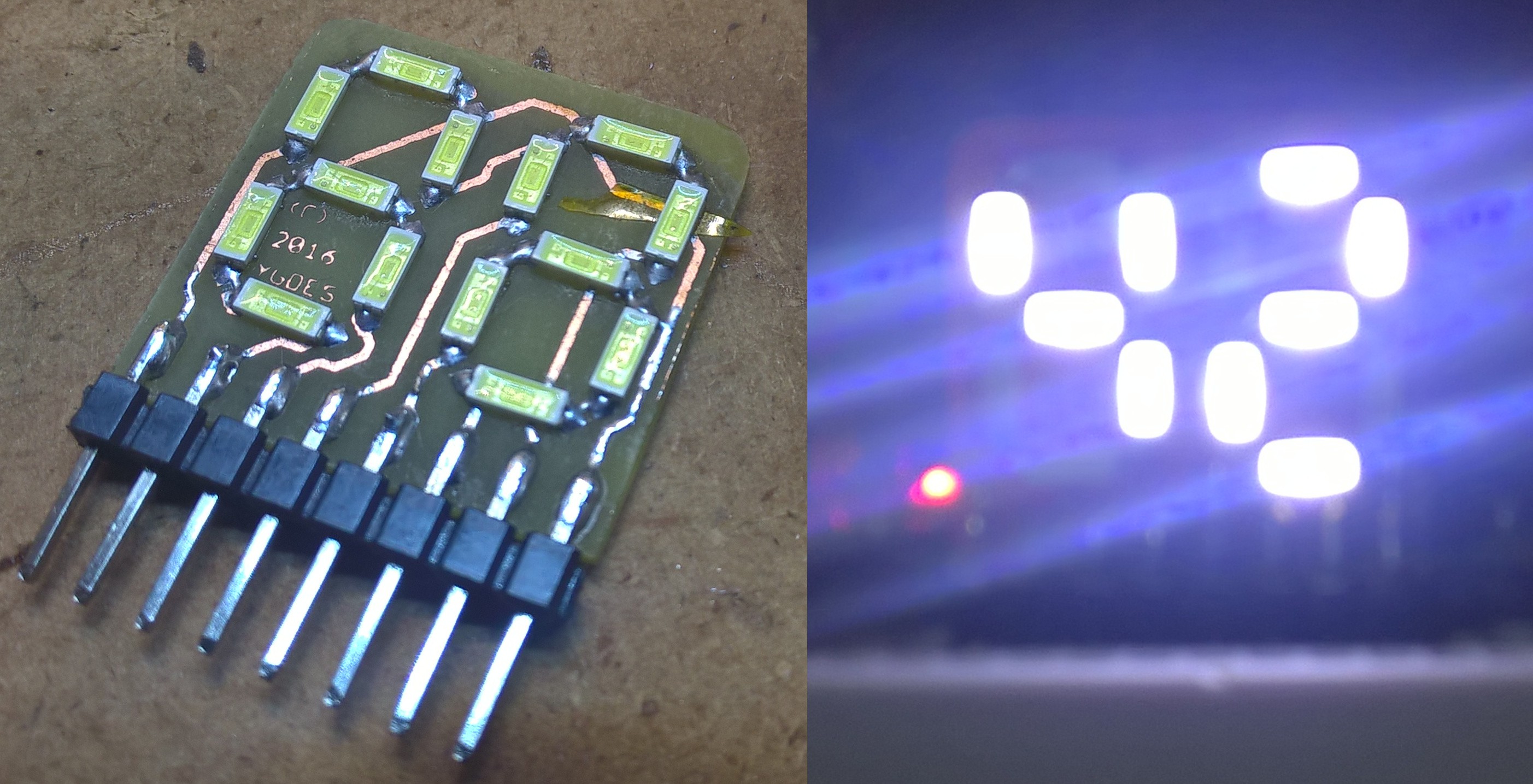
    I did some home etching the last weekend and I thought that would be a opportunity to throw also some 4014 module PCBs in. This is the result a first rev2 board:

    Beside that one trace with the capton tape the design is quite good to etch yourself.

    I used the same software I uploaded in the files section with adapted port defines. But when reviewing my code I found something bad: I do not know why I did that, but the code does do some multiplexing to much, and lights only one LED on at the same time, must fix that later.
    A second bug is in the schematic: On of LED B1 (1=left digit) or F2 is the wrong way around. So far I did saw B1 as wrong (only important for the software).

    The boards I order at OSH-park arrived also today. Will make some photos and soldering one soon. I did changed my order successfully to the rev2 boards so it should work with my type of LED.

  • Contrast enhancement with a diffusion layer

    Yann Guidon / YGDES09/06/2016 at 21:07 8 comments

    Since the beginning of the #DYPLED project, I've been wondering how to provide a better aspect with the least means. The display is nice as it is but it can still get better. Today I could finally test my hypothesis :-)

    This is the display modules, shot with my crappy smartphone camera :

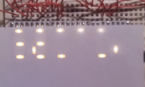
    Adding a simple, dumb sheet of white paper in front makes it look like this :

    This is obviously visually more pleasing, I think.

    Now, there are many problems to solve:

    • Paper is not durable. What plastic foil/film/sheet is best suited ?
    • The dots don't all appear nicely because the sheet could not stick to the surface of all the LEDs. Conclusion : the surface diffusor must be adhesive...
    • Does the PCB's soldermask color matter anymore ? Could black further enhance the contrast ?

    I'll test more ideas, meanwhile, I'd love to read yours in the comments :-)


    20160909:

    I tried various diffusion sheets from broken LCD screens. The results are not as expected. LCD diffusors do their best to not waste photons and spread light as much as possible.

    Paper OTOH absorbs quite a lot of light, which increases the contrast. I'll have to find a very thin adhesive label...

  • First working units

    Yann Guidon / YGDES09/06/2016 at 18:37 0 comments

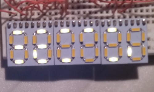
    After yesterday's discovery while assembling the first #DYPLED prototype, I couldn't resist trying this other type of 4014 LED on the rev. 0 boards that I thought would be useless.

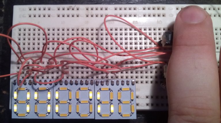
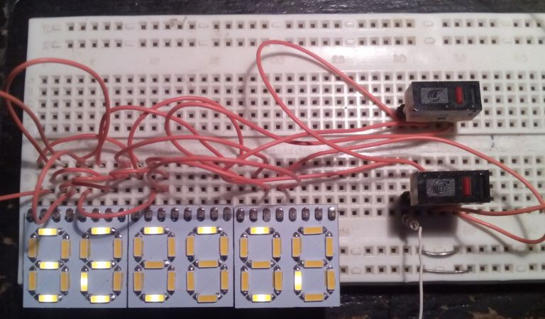
    I couldn't wire all the segments but you get the idea from this crude setup:

    I have noticed that the luminosity is very high at 3.3V and 1K series. Apply PWM ! Instead I lowered the voltage to around 2.7V to get a comfortable contrast.

  • a prototype

    Alex09/06/2016 at 16:34 4 comments

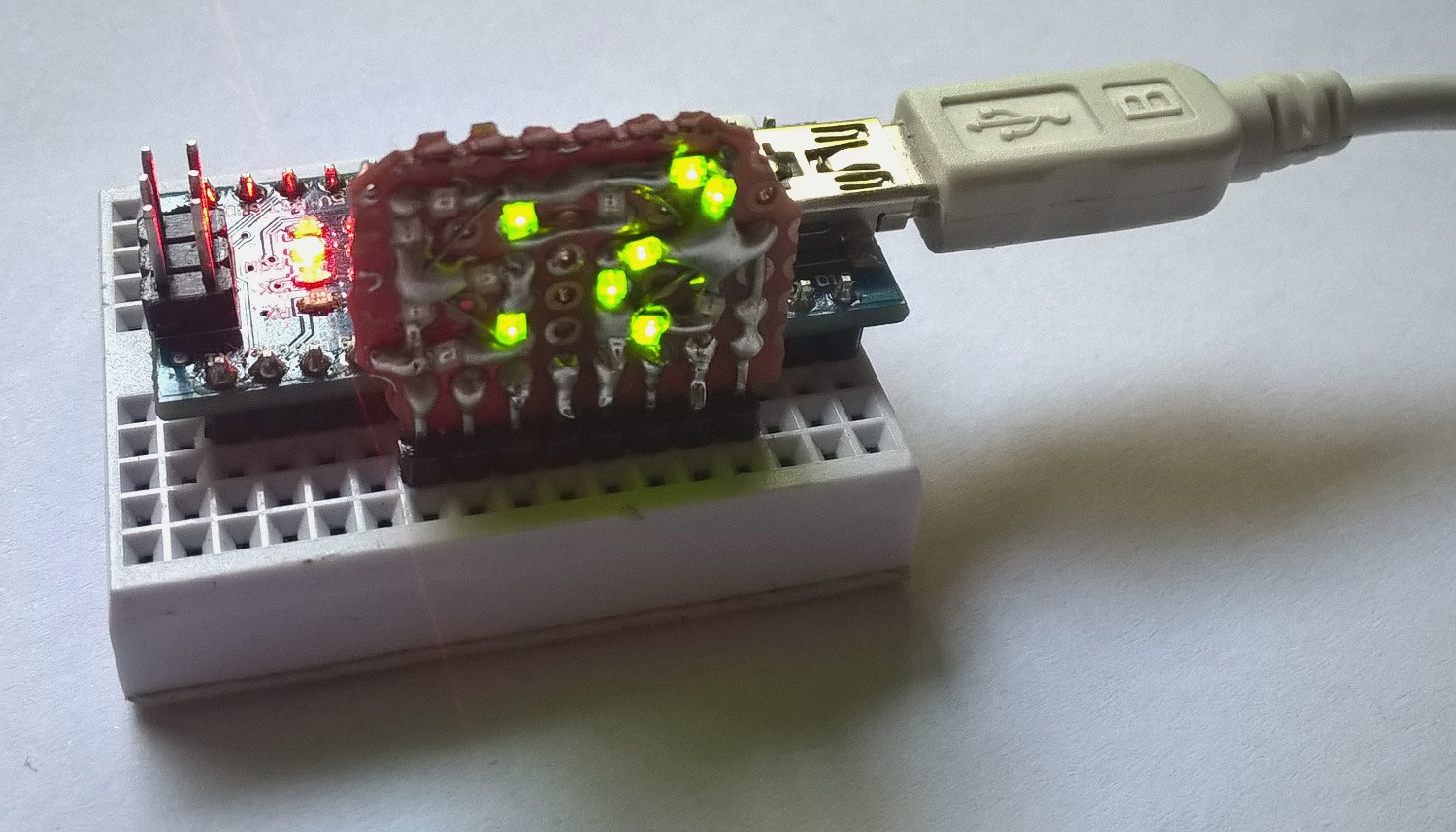
    In the file section you can now find my (al1's) AVR test code for rev0. To test this code I made this little quick prototype out of some prototype board and green 0805 SMD LEDs. It should be compatible to rev0.

    With 0805 you can read it not good (should be much better with 4014 LEDs). This is a "12".

  • There are two types of 4014 LEDs !

    Yann Guidon / YGDES09/06/2016 at 06:57 2 comments

    @al1 found that his 4014 LEDs have a reverse protection diode. I found the same and made the v.2 layout.

    Today, I started to solder the #DYPLED prototype so I opened a new batch of LED (warm white instead of neutral) and... NO DIODE !

    Alex, don't throw your PCB away, I'll solder mine and see what can be done. I'll see if I could send you a few diodeless LEDs :-)

    So in the end, there are 2 types of LEDs, hence 2 types of PCB...

  • Rev.1 PCB arrived

    Yann Guidon / YGDES08/29/2016 at 16:49 2 comments

    I received the very first order recently, and it won't be of much use...

    We already know that the circuit is wrong because of the protection diode (which could also be a Zener but at this point, who cares ?).

    Now, it's time to examine the PCB of the first version and look at other problems.

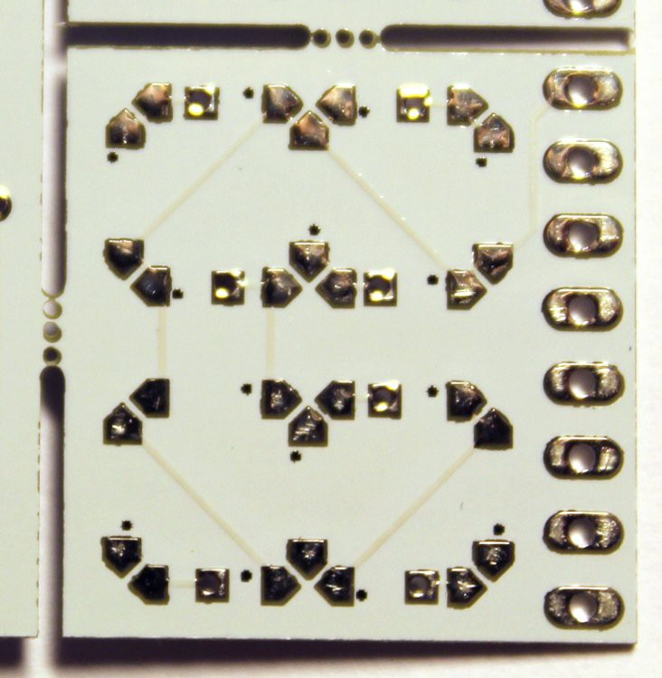
    The PCB did not get my "tented vias" and there are exposed signals under the LEDs.

    I have put the vias under the LEDs because I didn't want visual distractions.

    However the LEDs have heatsink pads that are electrically connected so short circuits will happen.

    Even worse: the HASL treatment increases the height of the via and adding insulating Kapton will make the part unsolderable because the pads won't touch the contacts...

    Fortunately, Rev.2 indirectly solved this problem because it's a single-sided PCB. No via.

    The diameter of the connectors seems to be ok and standard pins can go through it.

    I should try to solder a few LEDs, now...


    20160902:

    I soldered a few LEDs and it's not for beginners but it's not hard either. Just use very thing soldering wire, and apart from the problems with the vias etc., the layout and the footprints don't need to be modified. That's a relief :-)

    (yes, I didn't care much about the quantity of solder but it's not critical and it matters that it is easy to solder by hand)

View all 12 project logs

Enjoy this project?

Share

Discussions

davedarko wrote 09/06/2016 at 09:45 point

Demo pleasssse. :)

  Are you sure? yes | no

Yann Guidon / YGDES wrote 09/06/2016 at 09:46 point

Soooooooonnnn :-P

  Are you sure? yes | no

Yann Guidon / YGDES wrote 09/06/2016 at 18:55 point

Dooooone !

(see the files, sorry I lost access to my youtube channel)

  Are you sure? yes | no

Alain Mauer wrote 09/06/2016 at 09:41 point

Hi, do you have a video or a photo, where the LED's are powerd on? Just to see how it looks like.

  Are you sure? yes | no

Yann Guidon / YGDES wrote 09/06/2016 at 09:47 point

I'm focusing on #DYPLED at this moment... so it's more or less the same, only more embedded :-)

  Are you sure? yes | no

Yann Guidon / YGDES wrote 09/06/2016 at 18:55 point

See the files section :-)

  Are you sure? yes | no

Alain Mauer wrote 09/06/2016 at 19:10 point

Great. Thank you. A video says more then 1000 words :)

  Are you sure? yes | no

Alex wrote 08/21/2016 at 13:23 point

did some testing with two LEDs today: Noticed that this anti parallel multiplexing did not work with the 4014 LEDs I have. With normal 0805 LEDs it does work. So far I have no idea why? Will do some further investigation, but maybe some else already knows the solution.

  Are you sure? yes | no

Yann Guidon / YGDES wrote 08/21/2016 at 18:29 point

Oh.........

* What voltage did you use ?

* I apparently failed at the ground rule of electronics : TEST before committing

* Maybe your manufacturer has protection diodes ?

* I HAVE to test now...

  Are you sure? yes | no

Yann Guidon / YGDES wrote 08/21/2016 at 22:08 point

Maybe there is also an influence with the frequency. I try to drive at rather high speed (3KHz seem good) but there could be internal capacitive effects. OTOH the current is pretty low, with 1K Ohms in series... I must try.

And I know there are various manufacturers for this form factor, with different features and characteristics. I'll see if mine are behaving right. Tell me, what are the symptoms of your problems with your LEDs ?

  Are you sure? yes | no

Alex wrote 08/21/2016 at 22:24 point

I did try it it with 5V and different resistors (2k2,2k 470, 220). So far only with two LEDs anti parallel and one resistor. like this:

                        R       +-------|>|-----+
        o--------/\/\/\/\-----|                   |------------o
                                  +------|<|------+

No multiplexing, just DC. Depending on the polarisation one of the two LEDs should light, but with the 4014 LEDs this does not work (with 0805 it did). 

To get behind that I tested one of my 4014 LEDs in reverse direction (with constant 20mA) and I got reverse current over it. 

             I=20ma       4014 LED
  V+   o------->-------------|<|---------o  GNG

(I forgot to note the voltage, but I got 20ma over the LED and it was not destroyed after that)


I do not know why, but my LEDs behave not like diode. Only for emitting light it must be polarized right. A normal diode in series to each diode also solves this strange behaviour s expected. 

  Are you sure? yes | no

Yann Guidon / YGDES wrote 08/21/2016 at 22:28 point
OK

 So there is a protection diode in your LEDs... I'm setting mine up for a test.

Also I work at 3-3.2V, did you try at lower voltage ? 5V must emit a LOT of light :-D

  Are you sure? yes | no

Alex wrote 08/21/2016 at 22:30 point

yes 5V is quite bright without using a resistor >= 2k2. Never saw LEDs with protections diodes inside before. 

  Are you sure? yes | no

Yann Guidon / YGDES wrote 08/21/2016 at 22:36 point

Damnit, I just tested : 0.7V reverse voltage.

I have seen, 10 years ago, Luxeon LEDs with those f****** Zener diodes... what a PITA...

BUT this gives me a weird idea :-D

  Are you sure? yes | no

Yann Guidon / YGDES wrote 08/22/2016 at 00:24 point

  Are you sure? yes | no

Ted Yapo wrote 08/24/2016 at 16:57 point

Yann, can you explain more about the problems you encountered with Luxeon LEDs and the zener (TVS) diodes?  You mentioned it briefly below.

  Are you sure? yes | no

Yann Guidon / YGDES wrote 08/24/2016 at 21:28 point

 about 10 years ago, the then-best-in-class 3W LEDs were the Luxeon Star and I bought about 500 for a project. We found out the hard way that *some* have a Zener inside, probably to prevent damage to a string if a LED fails (avoids "open" string) and also dissipate ESD.
We had to sort them all, because they would make crazy short circuits if we are not careful with the screws (on bare metal).

What looked to Lumiled as a cool feature ended up as a nightmare and I believe this has not showed up since.

Until al1 found the culprit in the 4014.

  Are you sure? yes | no

Yann Guidon / YGDES wrote 08/18/2016 at 02:25 point

I sent a first batch to fab ! 0.6mm thick, white mask, might be delivered in 2 weeks...
I'm crossing my fingers :-)

  Are you sure? yes | no

Alex wrote 08/18/2016 at 13:28 point

I rhink my boards will be slower. I did orderd 0.8mm 

  Are you sure? yes | no

Yann Guidon / YGDES wrote 08/18/2016 at 15:48 point

0.8mm is nice.

Maybe I'll make the #DYPLED in 0.8 or 1.2mm thickness for better strength because people might want to use it on breadboards and it could break during insertion or extraction.

But I'm trying a very thin board to see how much I can reduce the height of the module, and next time I might even try flex :-P

  Are you sure? yes | no

Yann Guidon / YGDES wrote 08/24/2016 at 21:34 point

So the boards should arrive next monday. Too bad they are bad but I can try soldering stuff and validate my footprints (specially thought for hand soldering)

Fortunately there will be #DYPLED and #Yet Another Electronic Lampyridae on the board :-) Let's see if #DYPLED has flaws...

  Are you sure? yes | no

Yann Guidon / YGDES wrote 08/17/2016 at 18:51 point

Damnit, I spotted an error in the .brd, the extra via was not intended... I should have run DRC, right ??? there, fixed...

  Are you sure? yes | no

Alex wrote 08/17/2016 at 19:29 point

aaaaahr.. now I orderd boards with an error. But if you meant the unnecessary via next to the "8" it is no functional issue. 

  Are you sure? yes | no

Ray wrote 08/17/2016 at 19:31 point

cancel the order if needed if you cannot contact me directly! :^)

  Are you sure? yes | no

Alex wrote 08/17/2016 at 19:34 point

well as far I see Yann did just deleted this necessary via on pin 8 of the pinheader. So it is mostly a optical error. From a functional view the older version should work. 

  Are you sure? yes | no

Yann Guidon / YGDES wrote 08/17/2016 at 19:35 point

@al1 are you serious ? You DID order a board from my posted .brd ? :-D
Anyway the new version should work, you might be able to resubmit the order :-)

  Are you sure? yes | no

Alex wrote 08/17/2016 at 19:37 point

well yes.. had some left over coupon from osh oark (so it was also free). And no use for my 4014 leds. and it looks ok so far. Although I did also not noticed that extra via. 

  Are you sure? yes | no

Alex wrote 08/17/2016 at 19:41 point

as far I see the only difference between the two versions is that via. 

  Are you sure? yes | no

Yann Guidon / YGDES wrote 08/17/2016 at 19:42 point

@al1 so that's another surprise for me today :-P I never thought somebody would try it so soon :-D

  Are you sure? yes | no

Yann Guidon / YGDES wrote 08/17/2016 at 23:00 point

@al1 : would you join this project to share your experience with this board ? :-)

  Are you sure? yes | no

Similar Projects

Does this project spark your interest?

Become a member to follow this project and never miss any updates