20160816:
@Dylan C. asked me to contribute to the #DYPLED project. It's already pretty finished, quite sophisticated (overkill ?) and still requires non-trivial tools. But yesterday I made this quick PCB to help prototype the next revision of the board with the single-rail multiplexing method... So let's fork it !
Some specs:
From the users' perspective, the module is a very thin PCB (0.4mm, 0.6mm, max. 0.8mm PCB) to ease integration in other projects ( #Discrete YASEP is the project that needs this).
Visual comfort is important :
- high frequency multiplexing is easier on the eye (I found that 6KHz was a good frequency) but it depends on the application
- white background to reduce fatigue
- warm white LED is kinder than cold white
- no visually-distracting feature on the user-visible side (no via, parts etc.)
- even dimensions (8×0.1" or 20.32mm) to ease placement of multiple modules on a standard 0.1" grid (and the digits look regular)
There are 14 white LEDs, driven as 7 back-to-back pairs by a 3.3V digital signal (the integrated protection diodes limit the current, it's for display purpose, not lighting). The user must care about the multiplexing and dimming, to adjust the contrast.
Multiplexing is provided by one common rail/signal. Let it float if you blank the display, drive to 3.3V to turn one half of the LEDs on, drive to 0V to drive the other half. The tiny gotcha is: don't forget to negate the active logical values when driving to 3.3V, or else the pattern will be reversed.
Floating the rail (set the corresponding I/O to "high impedance") allows multiplexing several board, if you want to display 4, 6 or 8 digits instead of just 2. Just drive the individual common rails with a respective 3-states capable I/O pin to select which display to drive at a given time.
Note: If you drive the segments with more than 3.3V, you have to add series resistors with an appropriate value (left as an experimental exercise to the user).
Important !
Depending on the maker and model of LED, the 4014 format might embed a protection diode. This changes the multiplexing topology and there are 2 revisions of the board:
Version 0/1: No protection diode,
 parallel connection and resistor

                   |---|<|---|
                   |         |
Data ----\/\/\/----+         +--- Mux rail
                   |         |
                   |---|>|---|

Version 2: protection diodes
  serial connection, no resistor

Data ------|>|-----|<|----- Mux rail
Logs:
1. Damned protection diodes...
2. Version 2.0
3. Rev.1 PCB arrived
4. There are two types of 4014 LEDs !
5. a prototype (@al1)
6. First working units
7. Contrast enhancement with a diffusion layer
8. a second prototype - and some bugs (by al1)
9. Team work on HaD
10. My first v2 boards
11. Settling for Zener-less LEDs
12. New batch
.
 Yann Guidon / YGDES
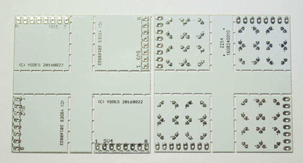

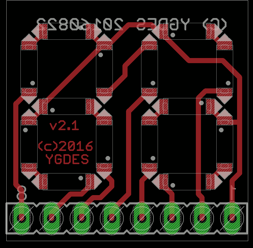
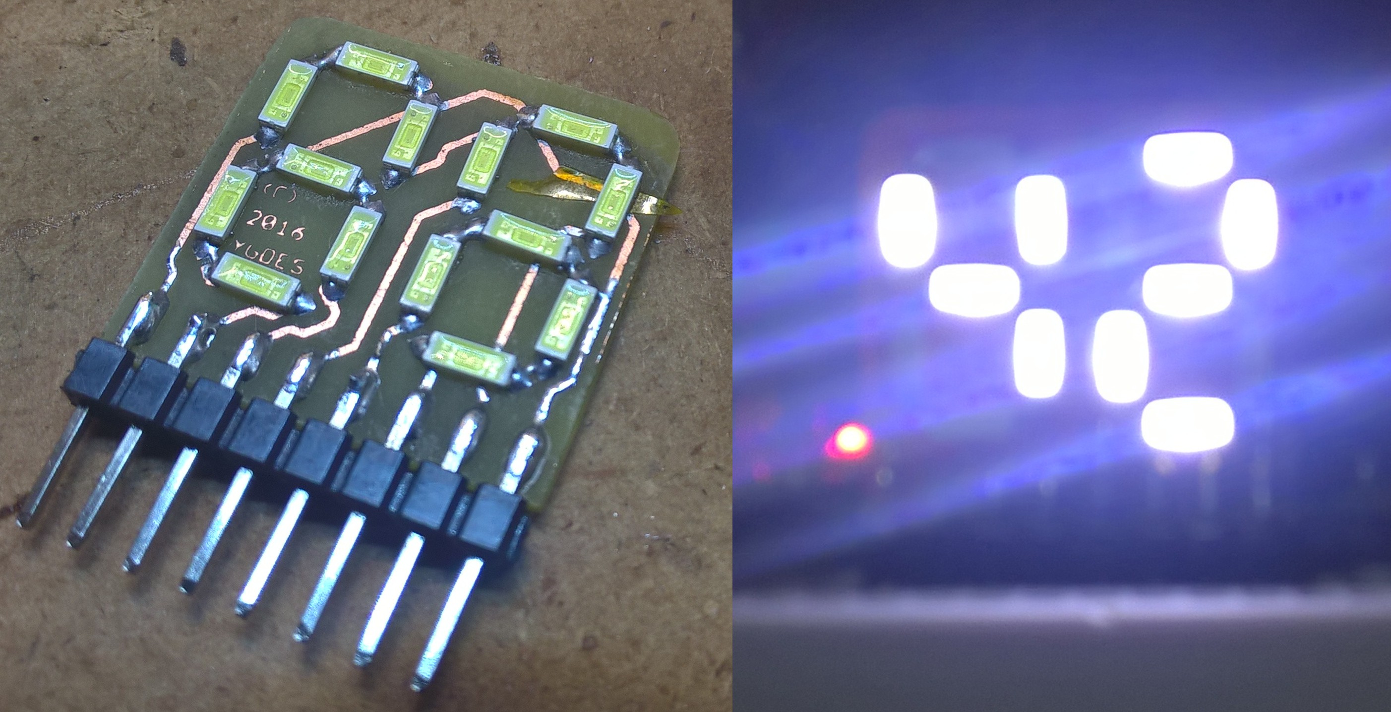
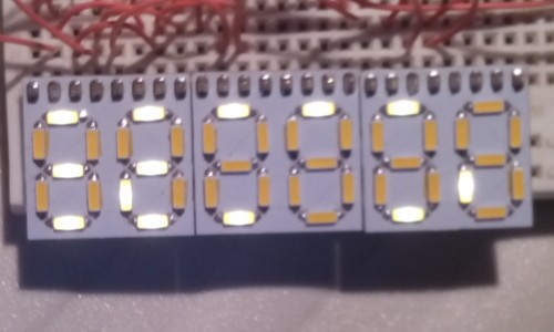
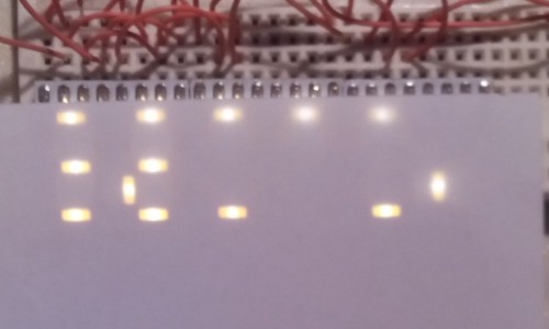
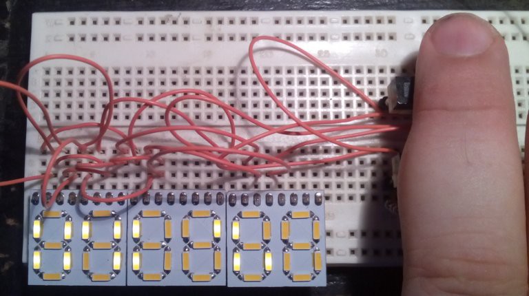
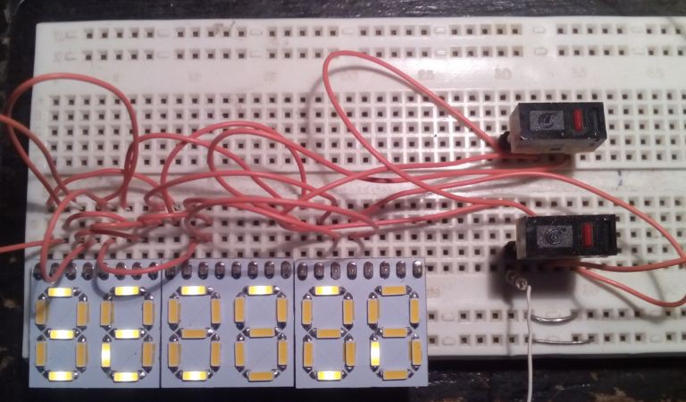
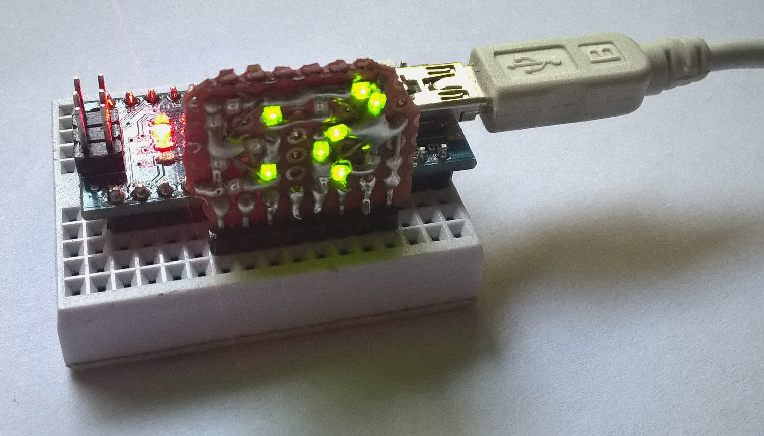
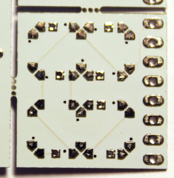
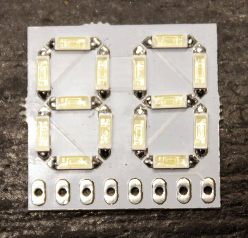 (yes, I didn't care much about the quantity of solder but it's not critical and it matters that it is easy to solder by hand)


Demo pleasssse. :)