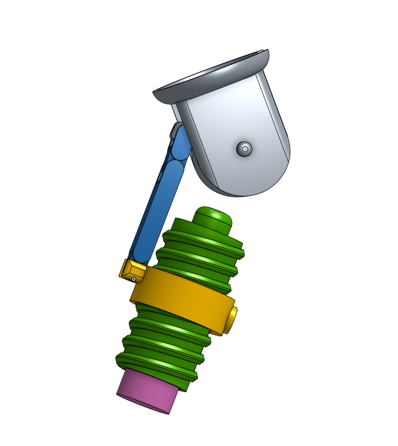
-
New joint assembled
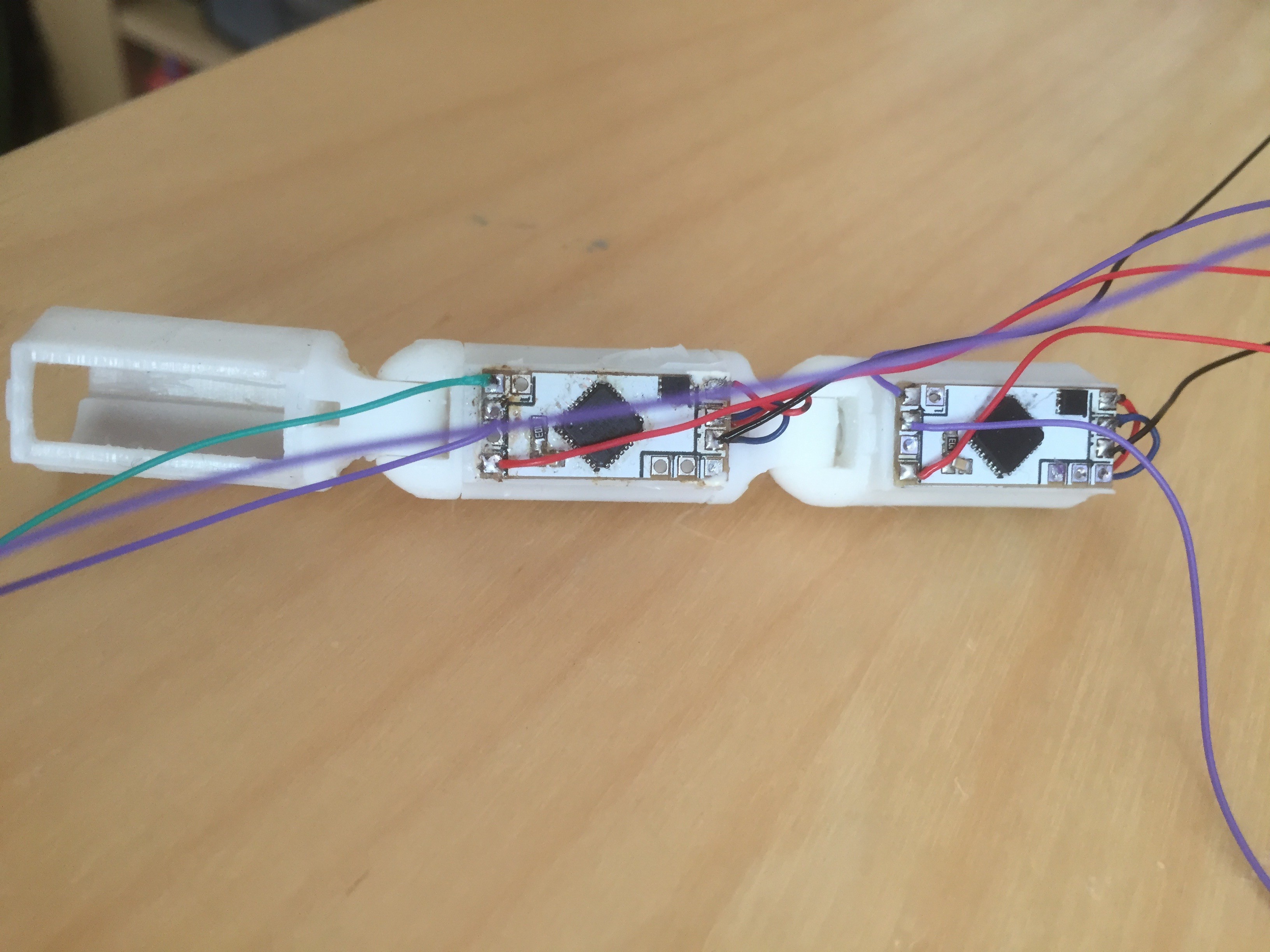
10/06/2016 at 05:17 • 0 commentsPrinted out a new instance of the joint and added the electronics. Here's it running.
The five sensors allows five positions of the actuator (the original electronics just allowed two). Because they're much closer together, I will probably see if I can support some sort of "micro step" to position the actuator between sensors. But that's for later - for now I'm very happy it all works.
-
Two sided PCBs
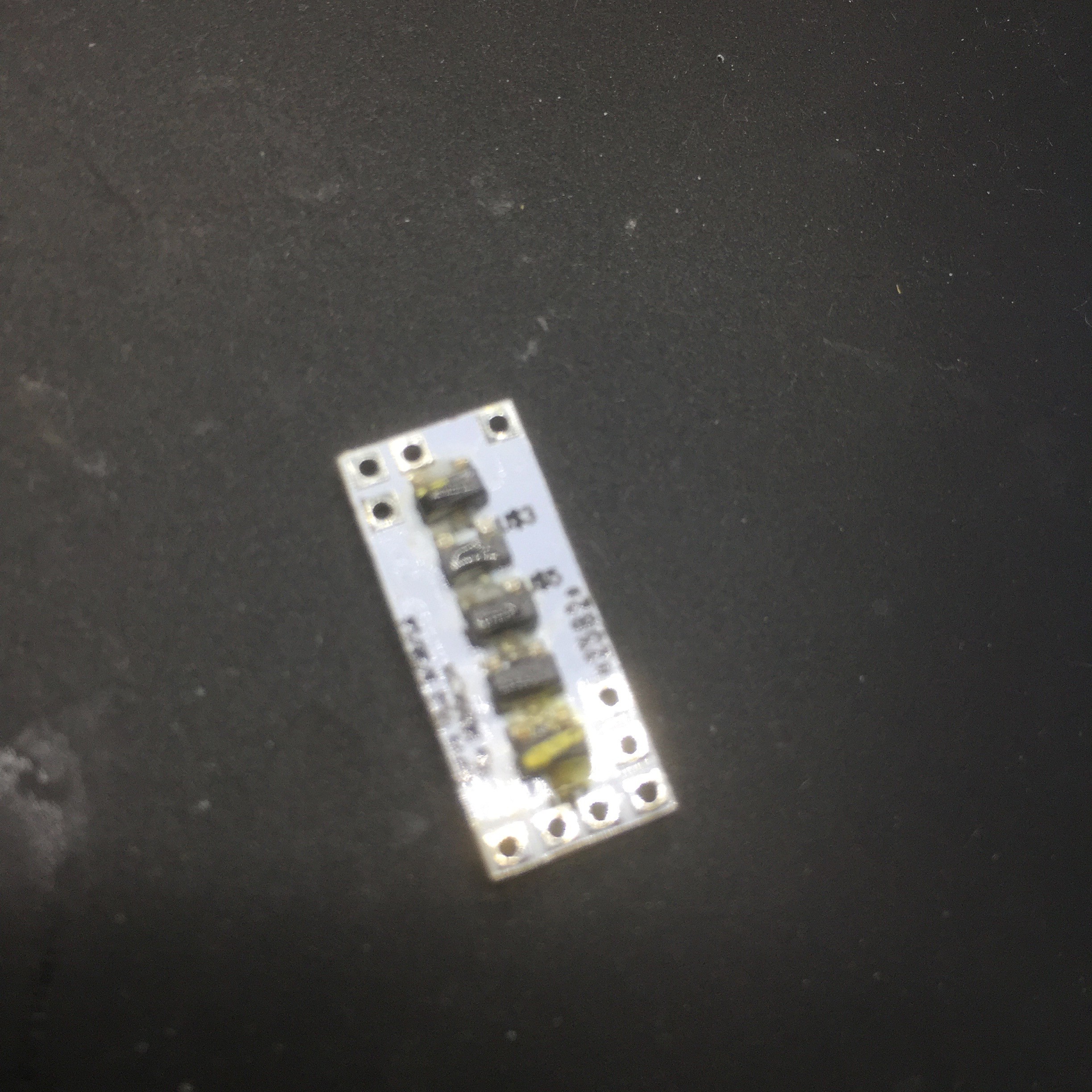
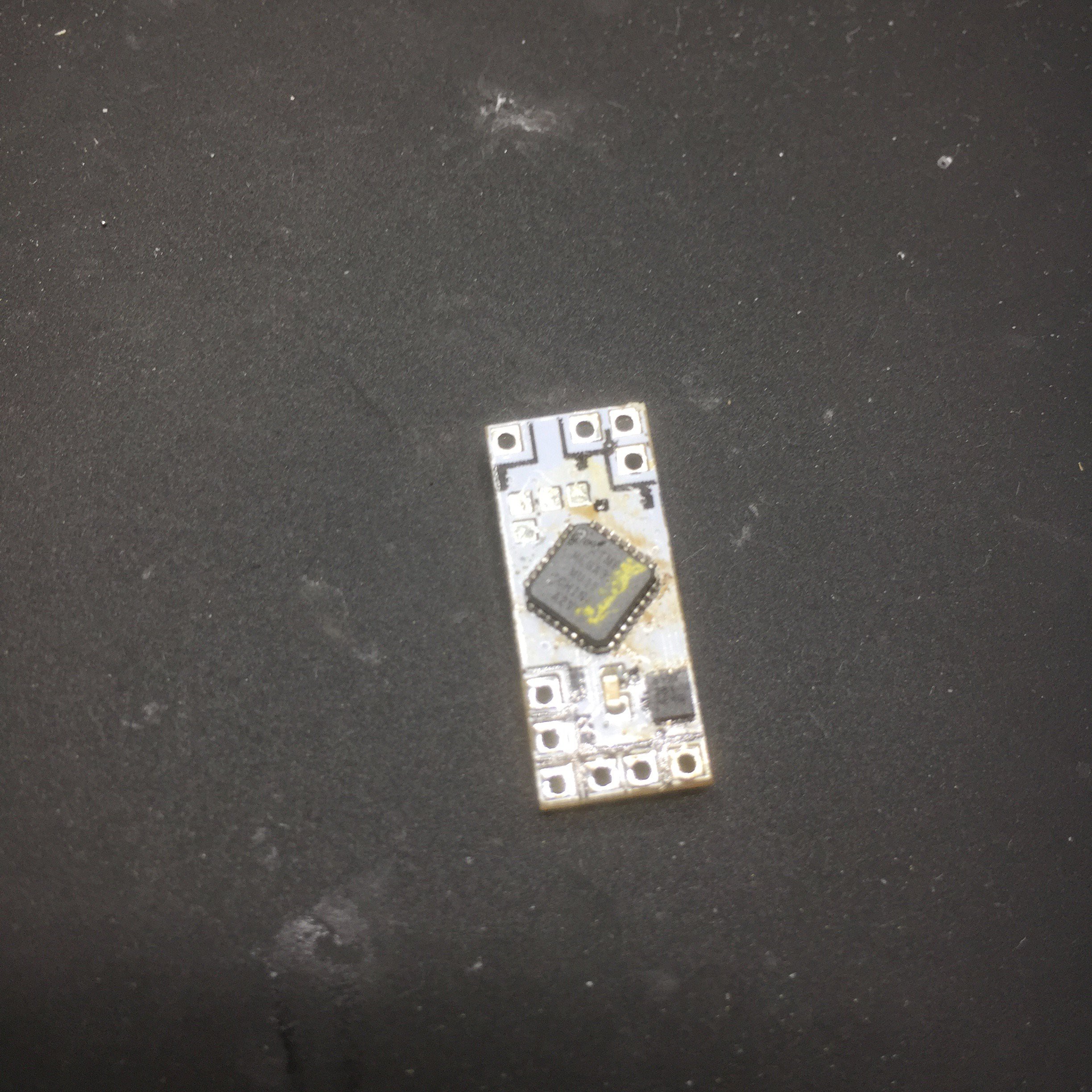
10/05/2016 at 18:28 • 0 commentsThis is probably the first two sided PCB I've ever worked with. The previous version had a couple of hall sensors on the back, but this one has five - so fully populated on both sides. And when I tried to solder this up, one side of the components fell off while I was assembling the second side. Arg!
After some frustration with this, I had to fix the first side with a little glue, let it fix, then solder the second. This worked ...
![]()
![]()
but it's rather messy. Notice the yellow ink (I melted a work mat onto the components while working this out). It's moments like this that I wonder if cheap PCBA is available somewhere.
The board tests and flashes correctly; the next step is to embed it in a joint.
-
New PCBs (v1.2)
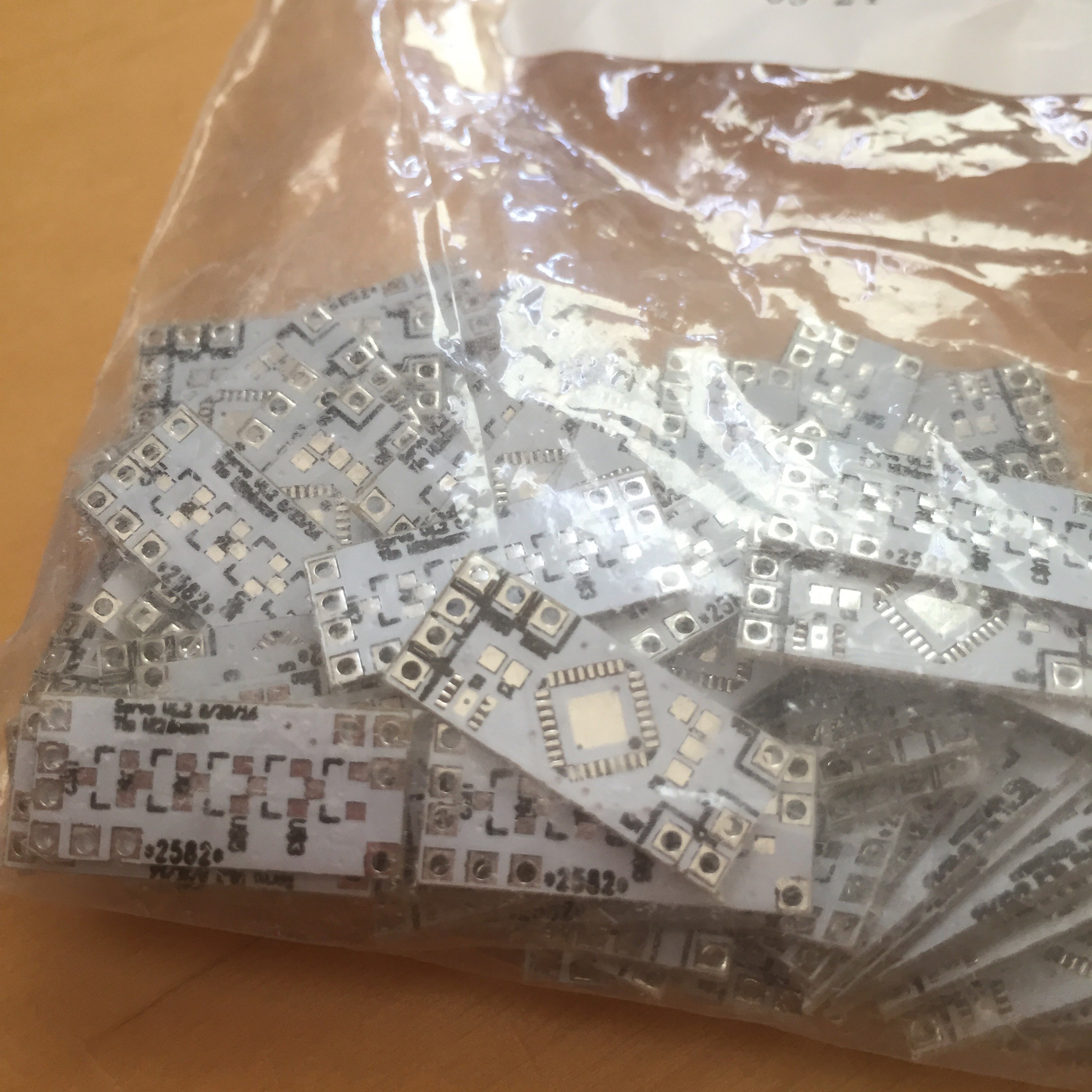
10/02/2016 at 23:43 • 0 commentsThis project's been a bit quiet while I waited for the new PCBs to turn up; and they did this week.
![]()
This version has a few improvements over the original:
- No pull-up resistor! Having a pull-up on reset annoyed me in the original design. This version attaches the reset pin to another input pin which, in software, will be set to input+pullup, so pulling up the reset. I left the pads in for the original resistor just in case this doesn't work. There's obvious a window between the board resetting and the pins being configured, but the nature of the gate transistors means this should be okay.
- Extra decoupling. I added pads for an extra decoupling capacitor. I've not seen a need for it, but it does no harm to have them.
- 5 hall-effect sensors. This board has pads for 5 hall effect sensors on the back; the original only had 2. This will give me finer control over the position of the actuator.
I intend to print and solder up a new joint later this week.
-
Pinshape
09/19/2016 at 05:06 • 0 commentsThis evening I made a quick PinShape entry which makes it easier to get hold of the STL files (no OnShape account necessary). You can find it here:
https://pinshape.com/items/26163-3d-printed-articulated-joint-v12
-
Double joint
09/18/2016 at 00:39 • 2 commentsHere's a quick photo and video of two joints connected together - mostly a test that one can life the weight of the other, and that the software network actually works as intended.
![]()
Video:
-
Version 1.2
09/11/2016 at 04:22 • 0 commentsI continue to iterate on the joint design. One of the joys - possibly problems - with a 3D printer is how easy it is to experiment with a new design. This one moves the fulcrum closer to the top of the worm gear, reducing the high of the joint by 20% compared to the pervious version. I'm trying to make things compact so this is important to me. The joint in operation is here:
I continue to be worried about the links between the rod, link and pivot. These are snap-fit "chain" like fittings. The FormLabs white resin version 1 was quite flexible which enabled these parts to be pushed together without any being deformed. This is less so of their version 2 resin and I'm not completely happy with the mechanically sound-ness of these as a result.
-
Version 1.1
09/08/2016 at 03:27 • 0 commentsI've uploaded a video of version 1.1. This redesigned some of the internal push/pull mechanism to remove the elastic and chain. Instead I use a more solid rod with a small chain piece connecting it to the pivot. Works well as you can see below:
-
Jig
09/06/2016 at 00:23 • 0 commentsFor testing purposes, I have my control PCB wired up to a set of pin headers on a scrap of protoboard. With the final joint, these pcbs need to have minimal wiring, but still be programmable. I usually use a Tag Connect for such things, but in they case I don't have space even for its small footprint, so I had to build a custom jig.
![]()
The photo above shows the completed jig. It was 3d printed so it matches the board connections perfectly, and then I used epoxied pogo pins to provide the electrical connection. All the programming pins are then attached to a standard AVR 6-pin ISP connector.
The jig design can be found here: https://cad.onshape.com/documents/3d72c1363b3b97e9fba5bf9c/w/46b2c15d39435988e5901c52/e/a0c99f7b3034ac30eab60ba3
-
Software: Networking
09/04/2016 at 05:52 • 3 commentsThe eventual robot is going to have *lots* of these joints. If I took a traditional servo approach, I'd need three wires per devices - power, ground and PWM. Assuming I bus the power and ground, that still leaves one wire per device for control; so with 30 devices that's 30 wires to thread and terminate on some eventual controller. I wanted something better.
My first plan was be to implement these joints as 1-wire devices. That way I could bus the control wire between all the devices and have just a single control wire at the controller. Unfortunately, while there are some nice Arduino libraries to implemented 1-wire slaves, my boards only run at 8MHz (the internal clock rate) which isn't fast enough to make them work, or at least work reliably.
Fortunately I had a fallback plan. I'm old enough to remember the Cambridge Ring - not some kind of upper class network of students spying for Russia - but an early networking protocol. Leaving aside the specific implementation details, it was essentially a ring of serial lines where each transmitter was connected to the next receiver (the last being connected back to the first). Messages are passed round the ring until they reach the destination.
So I build a ring network which works on a similar principles. Each Arduino TX is connected to the next Arduino RX, and then messages are encoded and sent around the network. To operate any given device a message is send along the network to the desired target where it is executed. The result is a large network of devices (~250) with just two wires and usable by anything with a serial line.
The RingNet is IOS level 3/4 - ordered, reliable delivered at least once, datagrams (Update 9/5/16 - originally the network was unreliable, but fix that today).
The networking code is here: https://github.com/aanon4/RingNet
-
Elastic-less
09/02/2016 at 05:52 • 0 commentsCurrently testing a new design version which does away with the elastic and replaces some of the chain with a fixed "rod". Some quick tests without the elastic look promising.
![]()
Custom Articulated Joint
I'm building a robot which requires small, articulated joints. Unfortunately I couldn't buy any, so I made my own.
 Tim Wilkinson