-
speed of light in air using Edlens equation
06/30/2014 at 18:02 • 0 commentsthis laser interferometer system uses a highly stabilized laser and precision optics to accurately measure distances. I am trying to build this so that is nearly as accurate as it’s resolution.This interferometer system is able to take measurements directly in line with the object being measured, and thus hopefully maximizing accuracy in that respect.
There are significant sources of error that will occur in this system due to operating the laser in open air.The index of refraction of air varies the path that the laser beams follow.These changes in path length result in errors in the measurement.The variation in the index of refraction can be calculated using an equation known as Edlen’s equation.
n = 1 + 7.86*10-4 *(AirPress)/(273 + temp) – 1.5*10-11* RelHumidity * (temp2 + 160)
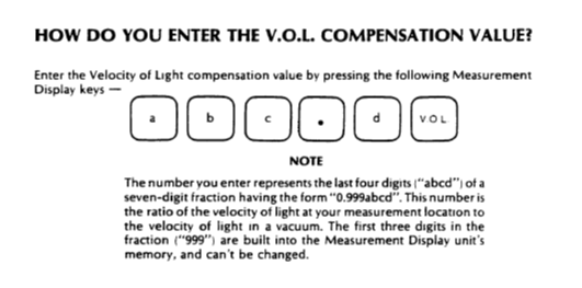
This correction factor is implemented in the controls of the 5508A measurement display.It can be input by using the original electronic sensors whos input would be used to calculate the index of refraction of air.That correction would then be used to correct the measured value of length.
![]()
The 5508A will accept the correction a correction factor from the front panel keys or from automatic input from electronic sensors attached to a connector on the rear of the 5508A or finally from input from the GPIB port on the rear of the 5508A.
![]()
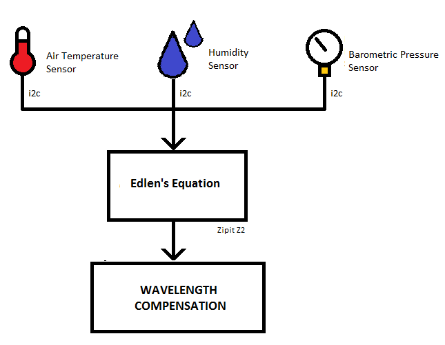
I don’t own the electronic sensors for the 5508A, so I decided to build a better set of sensors using a Zipit Z2 embedded computer running openWRT.I will use a set of sensors attached to the i2c communication connections available on the docking port of the Zipit Z2.I have written a small program to calculate the correction factor, using the barometric pressure, air temperature and relative humidity as inputs.
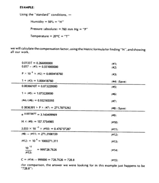
HP published the way that the electronics in the 5508A calculates the VOL factor. They took Edlen's equation and rederived it in a manner which is usable by the 5508A. The details of the arithmetic were given as a worked example so that people could reproduce thier work.
![]()
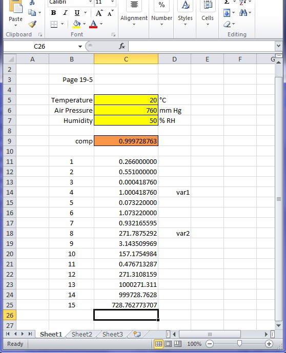
I took this worked example and reproduced each of the equations in a spreadsheet to verify my arithmetic.
![]()
Next I coded the arithmetic into a c language program and compiled it locally on the Zipit Z2 using a picoc compiler. The arithmetic worked out correctly :) . Now I have a compiled command line program which requires three command line parameters for temperature, humidity and barometric pressure.
Some interesting physics stuff can be seen from these equations. the equation step #14 shown in the spreadsheet and the HP screen shot shows a scale factor which can be used to show the speed of light in air. to do this take the value shown in step #14 and divide it by 1,000,000.
(1) 0.9997287628 = 999728.7628 / 1,000,000
The result is then multiplied by the speed of light in a vacuum, to give you the speed of light in air.
(2) 299,711,142.9 meters/second = 299 792 458 meters/second * 0.9997287628
The result of (2) is the speed of light in air with an air temperature of 20°C, humidity of 50% RH and barometric pressure of 650 mmHg.
This the program which performs this calculation is used in a shell script to automatically determine the correction factor and send it the the HP 5508A through its GPIB port. I'll describe the scripting later on.
-
slight change of plans
06/25/2014 at 09:16 • 0 commentshere is how the construction of the interferometer has gone so far. I cut the 4"x4" tubing from a 10 foot section of spare tubing that I've had in storage for about ten years. It was cut off using a router and straight edge. I drilled a set of holes to mount camera slider rail. The "Simple Camera Slider" was ordered with a bunch of extra nuts and screws and other hardware. The extra hardware came in handy as I was trying out every possible way to put the parts together.
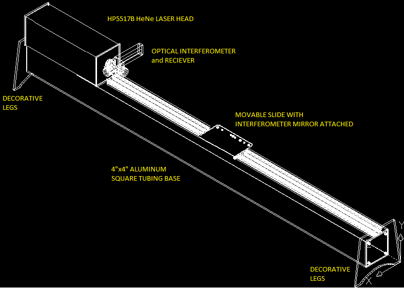
![]() The final arrangement of the receiver and the 1/4 wave plate was changed from the way I originally planned. In the photo above the laser beam leaves from the laser head, and then skims past the side of the receiver, then into the beam splitter. I could not get the arrangement shown in the CAD drawing to work. That was too bad, since I had also designed a mounting plate to hold all of the interferometer parts stationary relative to each other.
The final arrangement of the receiver and the 1/4 wave plate was changed from the way I originally planned. In the photo above the laser beam leaves from the laser head, and then skims past the side of the receiver, then into the beam splitter. I could not get the arrangement shown in the CAD drawing to work. That was too bad, since I had also designed a mounting plate to hold all of the interferometer parts stationary relative to each other.![]() Above is a picture of how the slider is going so far. The retro-reflector is the mirrored object. It has a flange for mounting it still. I had a leftover conduit clamp which was a close fit to the outer circumference of the retro-reflector body. I wrapped a scrap piece of wool around the retro-reflector body, and slipped it into the conduit clamp, and now it is held steady enough for playing around with different ideas, until I get this project built in a way that works the best.
Above is a picture of how the slider is going so far. The retro-reflector is the mirrored object. It has a flange for mounting it still. I had a leftover conduit clamp which was a close fit to the outer circumference of the retro-reflector body. I wrapped a scrap piece of wool around the retro-reflector body, and slipped it into the conduit clamp, and now it is held steady enough for playing around with different ideas, until I get this project built in a way that works the best.![]() Above is a view from the opposite angle as the first picture. All of the optical components are from ebay trappings as well as the receiver and measurement display unit. The laser head was purchased from the proprietor of repairfaq.org It is a completely functional laser head, with low mileage and lots of cool warning stickers.
Above is a view from the opposite angle as the first picture. All of the optical components are from ebay trappings as well as the receiver and measurement display unit. The laser head was purchased from the proprietor of repairfaq.org It is a completely functional laser head, with low mileage and lots of cool warning stickers.The cabling between the 5508A measurement display, the laser head and the receiver was a DIY project which eventually took two days to complete. The Mil-Spec canon connectors are not standard off the shelf. For some unknown reason the arrangement of the 18-pins in the body of the connector is different than the current connector available from my distributors. I ended up buying two of the ones that are available and pulling the pins and internal rubber guts from the connector. I then had to rotate the relative position of the body, then reinsert the pins. I then started burdening repairfaq.org with 50 questions about how to wire the three components together. His summary of how to build the cable is given here ( http://www.repairfaq.org/sam/laserhst.htm#hst5508x1 ). After soldering the connectors using a 25 foot section of 18 conductor cable, I added a second 4-conductor cable to the connector on the 5508A side. The receiver also has a weird connector. The connector has a BNC style shell, but has four pins on the inside. Two are male, two are female and the nylon spacer is an interlocking style. I could not find the connector part number in any searches so far. I ended up using male and female insertion pins from a couple db-25 connectors. After I wrapped the exposed pins in masking tape, I pushed them in place in the reciever connector and glued them in place. The wire ties shown in the picture above steadies the assembly as well as giving a good strain relief for the wiring.
-
How it works (part one)
06/24/2014 at 08:20 • 0 commentsThe hardware that will be integrated together and their purpose is:
![]()
- HP5528A Laser interferometer measuring system.The laser interferometer is the primary measuring instrument for this overall project.It is capable of resolving the motion of a movable mirror to within 0.000001 inches or 0.00001 millmeters.This laser interferometer is an older model instrument, but I believe the system is in good condition and completely functional.I believe it is reliable and might even be able to be calibrated.This laser interferometer consists of a HP5508A measurement display/controller/power supply, a HP5517B HeNe laser head, HP10780 remote receiver, and an optical Michelson interferometer consisting of the following part numbers; HP10706A beam splitter, (2) HP10703A retro reflectors and a ¼ wave plate.
- Zipit Z2 embedded palmtop computer running openwrt.This computer will be programmed and wired to a set of temperature sensors to measure the material temperature of an object being measured, an additional set of air sensors for temperature, humidity and barometric pressure, which will be used to automatically calculate the speed of light in the air surrounding the interferometer.The Zipit Z2 will also be wired to a Prologix GPIB-USB Controller for communications back and forth between the HP5508A and the Zipit Z2.The Zipit will send GPIB commands to the HP5508A after calculating the average temperature of the material temperature sensors as well as the speed of light value.The Zipit Z2 will also be used as HTML server.It has a WiFi interface, which allows measurements to be displayed remotely on a browser with access to my network.The HTML server will also provide an interface to control the HP5508A remotely.
- The linear track and carriage are assembled from a turn-key solution provided from the following web site. https://www.inventables.com/projects/simple-camera-slider#overview The movable retro reflector for the laser interferometer will be bolted to the moveable carriage.Also the remainder of the optics will be bolted to the rail itself.The rail lends itself well for bolting additional fixtures for holding clamps and such for attaching objects to be measured.
This measuring machine will work in the following manner.A laser interferometer will be arranged so that the moving mirror of the interferometer will be attached to a movable slide attached to a linear aluminum rail.The movement of the slide on the rail will then be directly measured by the laser interferometer.The laser, electronic receiver, optics and the linear rail will be bolted to a 4”x4”x90” square aluminum tubing.Additional fixtures will be constructed to hold items to be measured in place against the linear rail.The movable slide will be moved from a fixed reference position to a point where it makes contact against the item being measured.
![]()
- The laser interferometer has a centralized electronic control box known as a 5508A Measurement Display.This unit does the following
- Provides power to operate the Laser Head and Optical Receiver
- Converts measurement information into a number that represents a unit of length
- Provides the control and display interface for the person operating the interferometer
- Provides electrical interface for material temperature sensors and environmental sensors
- Provides a GPIB interface
The rear of the 5508A has several electronic connectors for the original temperature sensors designed for measuring the temperature of the object whose length you are measuring.There are connections for each three individual temperature sensors.The 5508A will operate with zero, one two or three sensors hooked up.The 5508A will calculate the average of the temperatures measured.The average temperature is used with the coefficient of thermal expansion to figure out how much change in length there would be if the thing you are measuring was currently at a standardized temperature.If there are not temperature sensors attached to the 5508A, then you can manually type the temperature from the keyboard on the front.Finally the temperature can also be entered from the GPIB interface.
For this project I will use a Zipit Z2.The Zipit will have three i2c temperature sensors.Each of these will be wired to the Zipits external docking connector, where the i2c connections can be accessed.The sensors are calibrated and a lookup table was created so that temperature sensor values are correlated to the temperature measured by an external digital thermometer.An awk script will lookup the temperature after the i2cget command returns a value.Each of the three temperature sensors work in this manner.The average of the three sensors are then transmitted back to the 5508A by using the echo command and sending the output to a USB-to-GPIB adapter.
(more on this later)
-
Inspiration for this project
06/20/2014 at 08:36 • 0 commentsInspiration for this project is from two other measuring machines. One of these is a commercial measuring machine manufactured by Pratt & Whitney and the second is the NIST Length Scale Interferometer.
(http://www.prattandwhitney.com/images/customer-files/measuring_systems1.pdf) This machine is a Metrology Laboratory Measuring Machine, which are able to be certified traceable to NIST, and is able to measure up to 120 inches with one micro inch resolution.It uses a Hewlett Packard 5528A laser interferometer system as it’s measuring system.This is convenient since over the last few years I have collected many of the individual components of a HP5528A system from online auctions and other online sources.This Pratt & Whitney measuring machine has most of the features that I would like to end up with my project.
My second source of inspiration for this project is the saga of the history, design and evolution of the NIST Length Scale Interferometer.http://www.nist.gov/calibrations/upload/104-225.pdfThis document describes the efforts of the United States National Bureau of Standards (now known as NIST) efforts to design and build a Laser Interferometer Measuring Machine.Original experimentation and construction of a laser interferometer began sometime around 1958 and by 1961 researchers had built a measuring machine capable of measuring across a range of about 10 centimeters.Major changes to the interferometer occurred in 1965 and 1966 with advancements in laser construction.Finally in 1979 the NIST Length Scale was integrated with a HP5526A.Further improvements in this measuring machine resulted in a range of 2 meters and a measurement uncertainty of about 5X10⁻⁸ meter by 1986.The document linked above describes in detail a list of sources of uncertainty in measurements and the researchers methods to minimize the uncertainty as well as calculating the individual contribution of these uncertainties.
In the world of metrology there is an orthodox method to identify and measure the individual sources of uncertainty in your measurement.This orthodox method basically provides a statistical description of how well you are able to make a measurement.It works by identifying and categorizing as many possible sources of error in your measurement, and calculating the effects of these sources of error across a range.
An example of what I mean is if there is an error in measuring the temperature of a length of metal, then there will be a resulting error in the calculation of how much length change of the object due to the changing temperature.However if the uncertainty of the temperature measurement is known, then the uncertainty of the length change can be calculated as well as the size of the overall length change.
Many sources error are identified and their effects on the measurement are estimated. The estimate is done using statistical methods.These uncertainties are then combined together to provide you with a number which describes your ability reliably make an accurate measurement.
I will use the NIST document as a basis to identify my sources of uncertainty for this project. I will then use the same statisical methods to determine my final measurement uncertainty, when I am making measurements.
repurposed luminiferous aether detector
over the last few years, i've build up a functional laser interferometer. now i want to use it to accurately measure distance.
 Beaglebreath
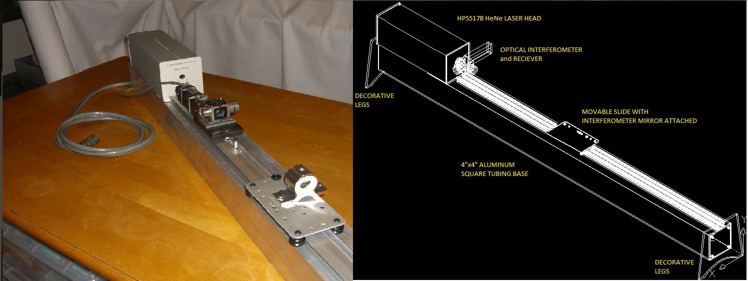 The final arrangement of the receiver and the 1/4 wave plate was changed from the way I originally planned. In the photo above the laser beam leaves from the laser head, and then skims past the side of the receiver, then into the beam splitter. I could not get the arrangement shown in the CAD drawing to work. That was too bad, since I had also designed a mounting plate to hold all of the interferometer parts stationary relative to each other.
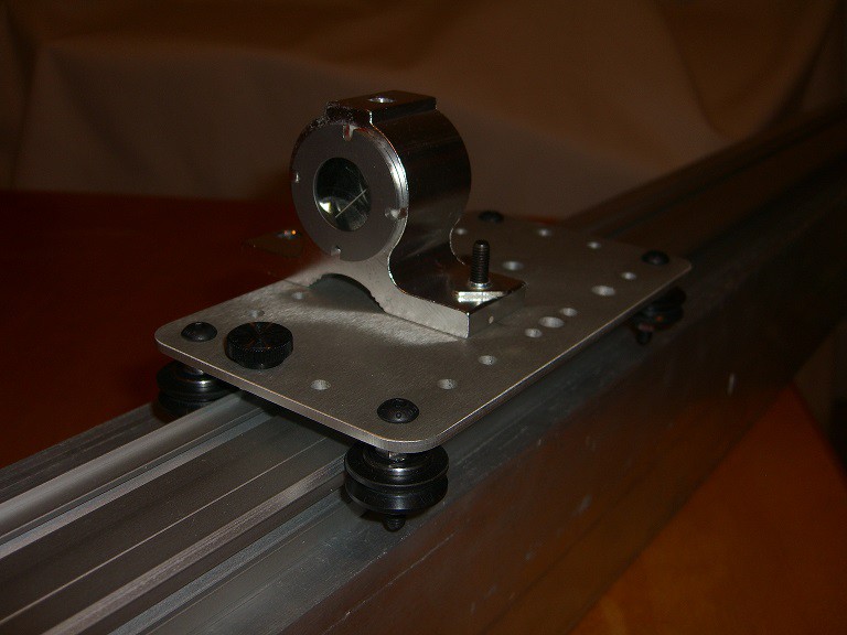 Above is a picture of how the slider is going so far. The retro-reflector is the mirrored object. It has a flange for mounting it still. I had a leftover conduit clamp which was a close fit to the outer circumference of the retro-reflector body. I wrapped a scrap piece of wool around the retro-reflector body, and slipped it into the conduit clamp, and now it is held steady enough for playing around with different ideas, until I get this project built in a way that works the best.
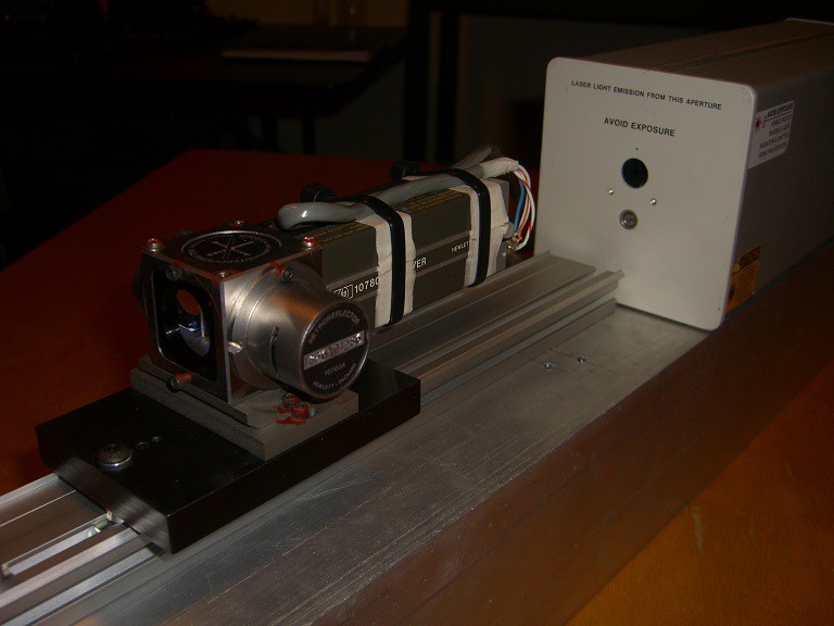 Above is a view from the opposite angle as the first picture. All of the optical components are from ebay trappings as well as the receiver and measurement display unit. The laser head was purchased from the proprietor of repairfaq.org It is a completely functional laser head, with low mileage and lots of cool warning stickers.