-
Electronics & Wiring
02/01/2017 at 08:47 • 0 commentsI chose the RAMPS 1.4 board because that was the most accessible controller at the time (Q1 2014). The Marlin firmware was mature and had a huge user base. It also had good support for delta configurations. I planned to install the control board, power supply and axis motors underneath the bottom plate. This kept most of the wiring down the bottom. I would still need to run wiring up to the top for the endstops and any wiring to go to the end effector. Some printers have the bowden tube and wiring attached about half way up one of the towers. Whilst this keeps the bowden tube short for good retraction/ooze characteristics, it meant that I would have the extruder hanging off the side of one of the towers. This didn’t align with my design goal of having everything inside the triangular footprint of the printer. I decided that the extruder would be attached underneath the top plate and the Bowden tube would run down from there. Some small ducting ran up the inside of the rear (Z axis) tower and then cables would run alongside the bowden tube from the top (with the aid of spiral cable wrap).
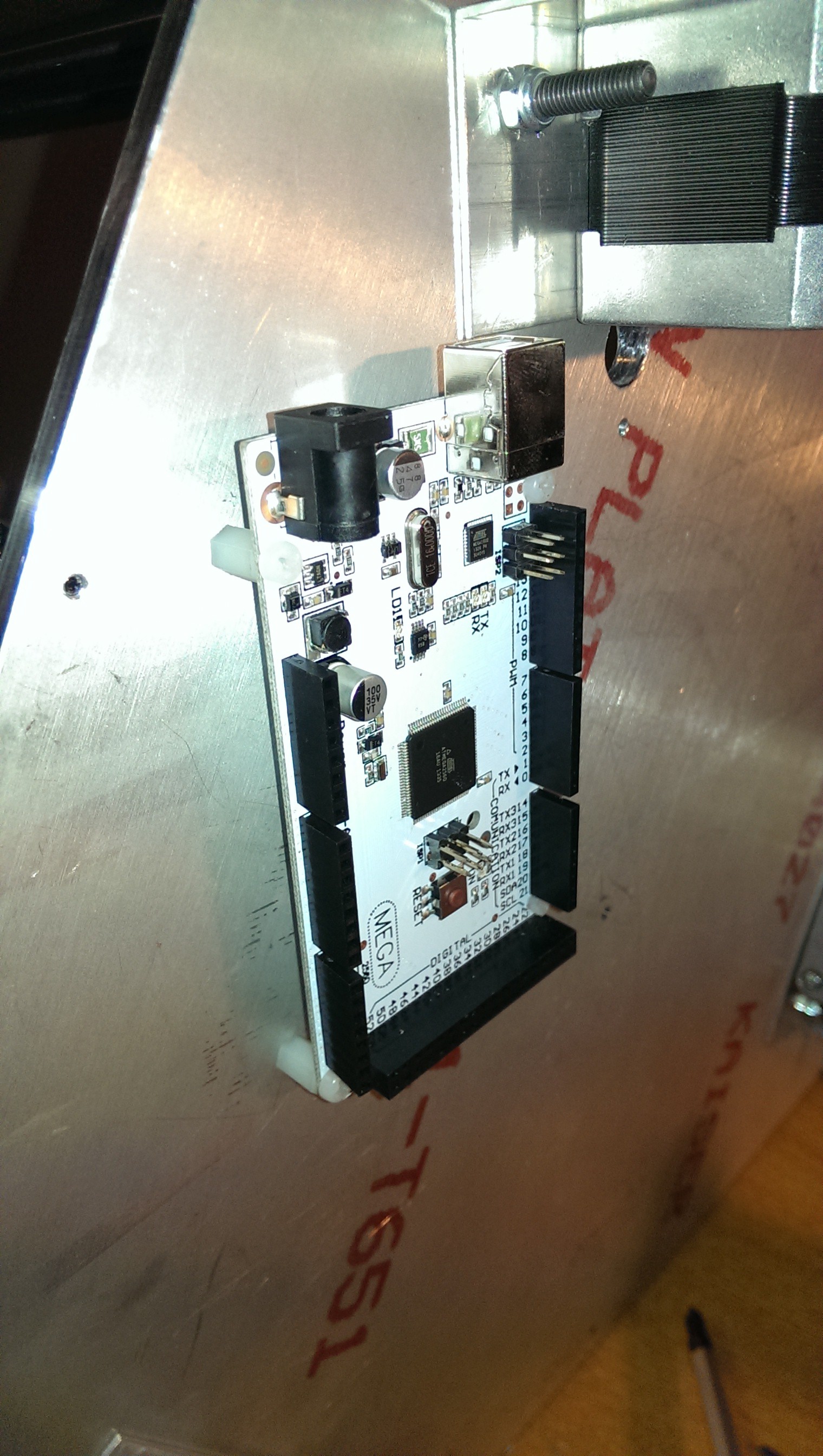
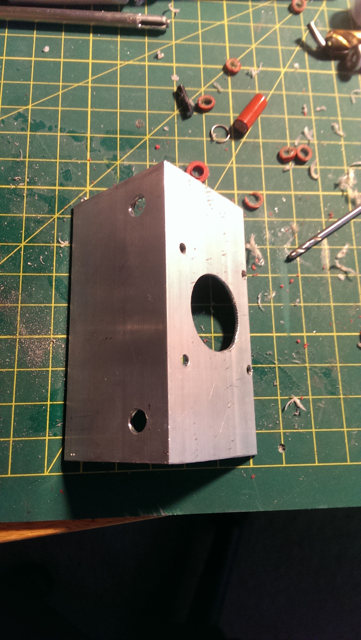
I had not received my power supply yet but had my battery charger supply (12V 30A) available. I knew the approximate dimensions so tried to allow for it when mounting the RAMPS board. I was really happy with the decision to use aluminium plate as drilling and tapping M3 holes everywhere was super easy and very secure to mount things to.
![Nylon standoffs in tapped M3 holes]()
Nylon standoffs in tapped M3 holes
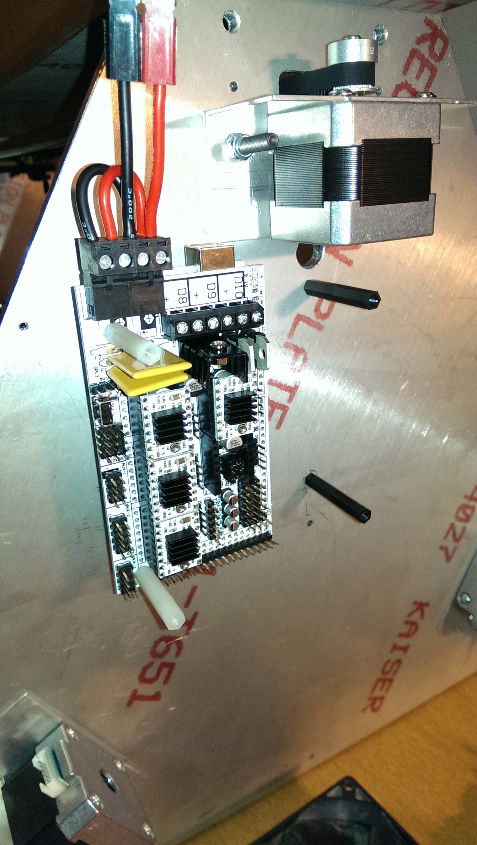
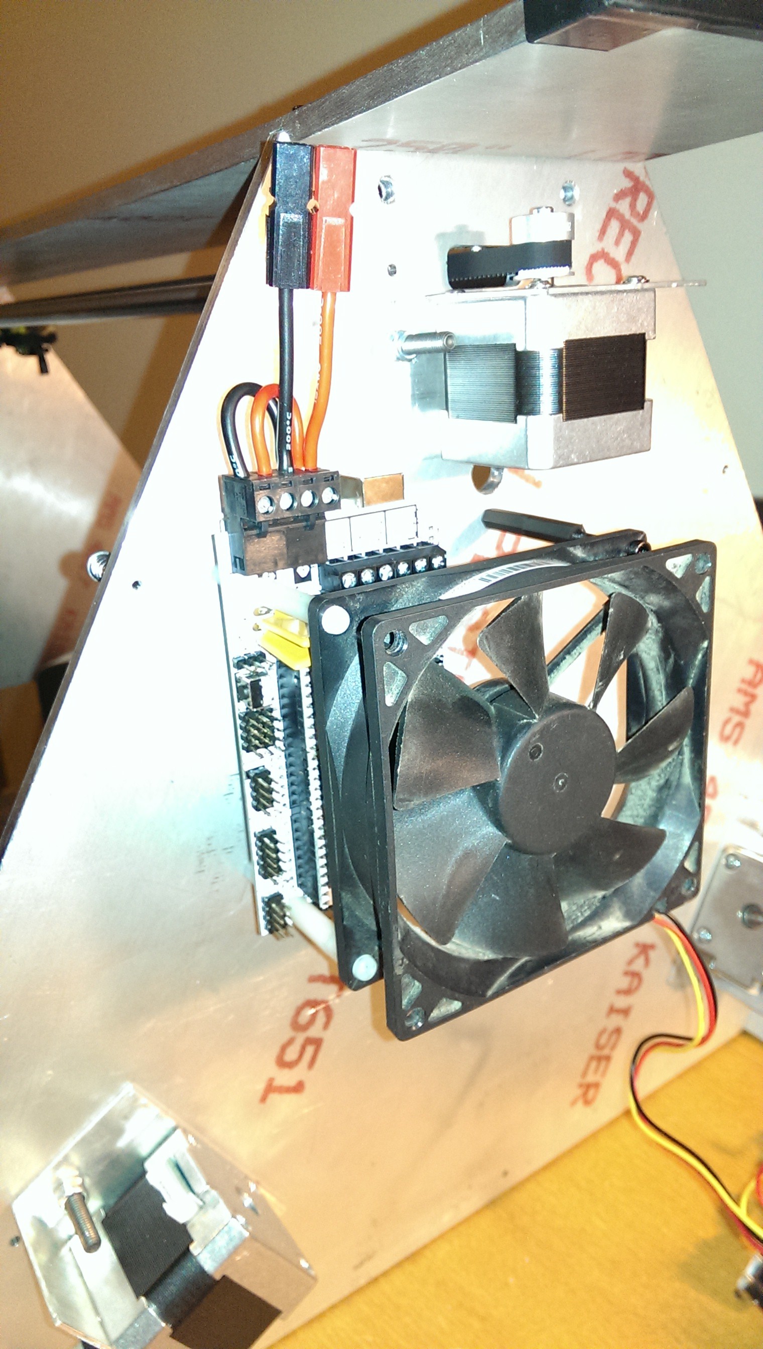
I had a few spare computer fans lying around and thought it would be a good idea to actively cool the controller. I’d read that the stepper motor drivers could get quite hot and would benefit from active cooling. It was simple to tap a few more holes and add some more nylon standoffs to mount a fan.
![Standoffs]()
Standoffs
![Cooling fan]()
Cooling fan
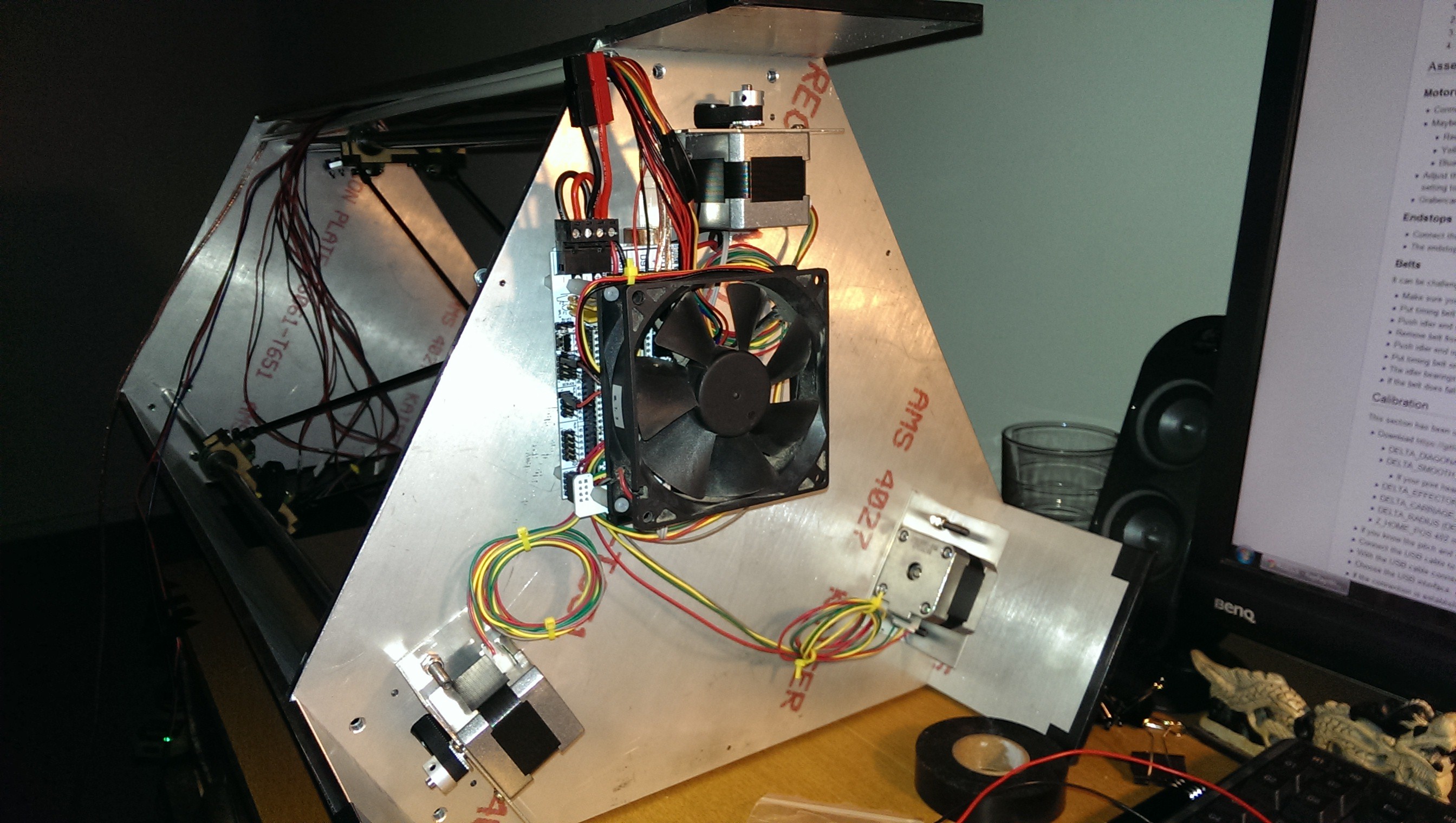
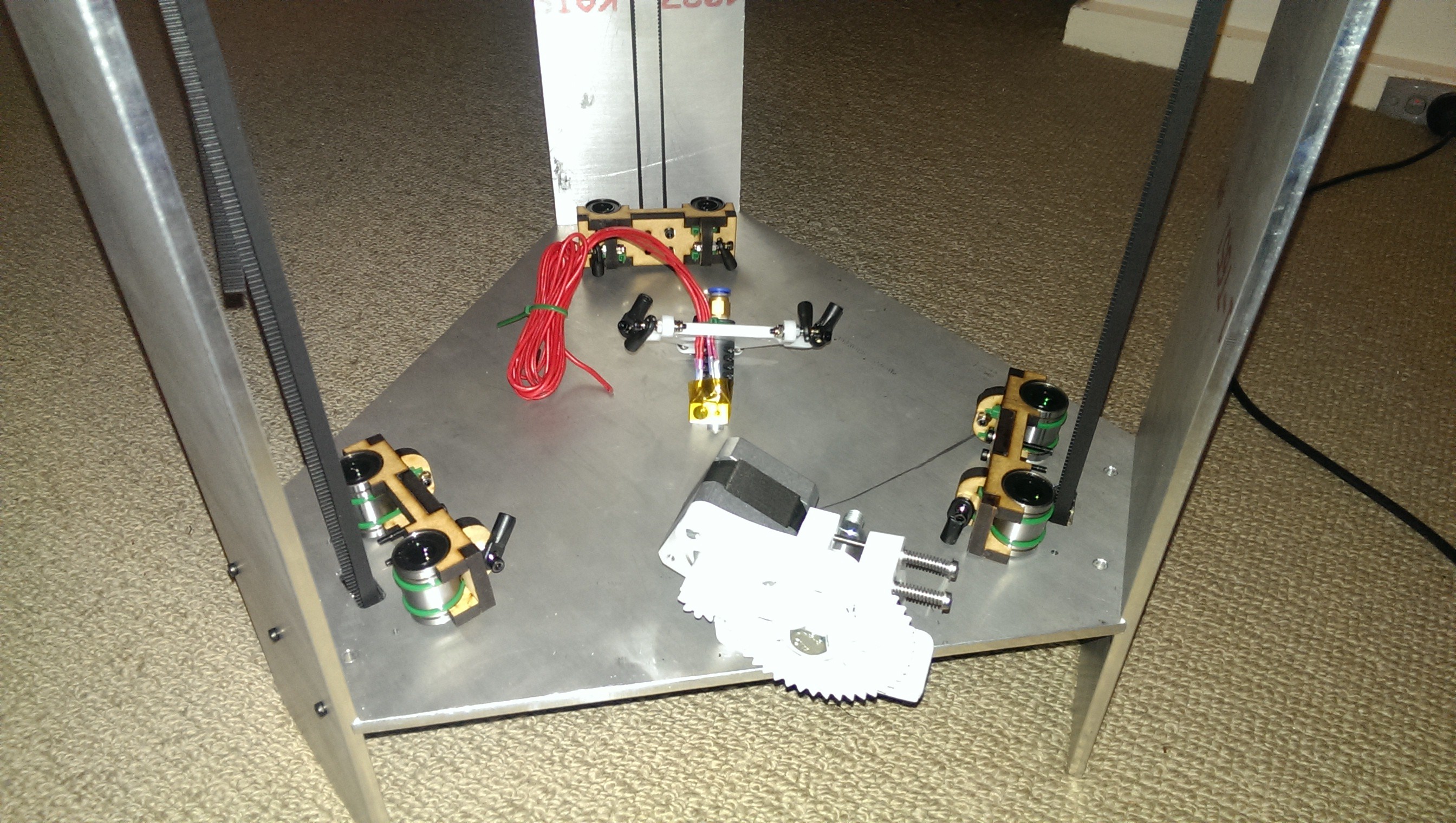
The electronics kit from LearCNC came with heaps of pre-terminated wiring. I was able to use most of the provided wires and easily extended some of them for the further away items. The picture below shows most of the bottom wiring complete. I had some spare Anderson connectors lying around. These would be used to connect to the temporary power supply and later to the “integrated” power supply.
![Wiring is half way there]()
Wiring is half way there
I ran the ducting all the way up to where I had mounted the extruder. Wires could then be cable tied to the start of the Bowden tube. In the picture below you can also see the three JR style plugs for the endstops. Endstops will be discussed in a later section.
![Wire routing]()
Wire routing
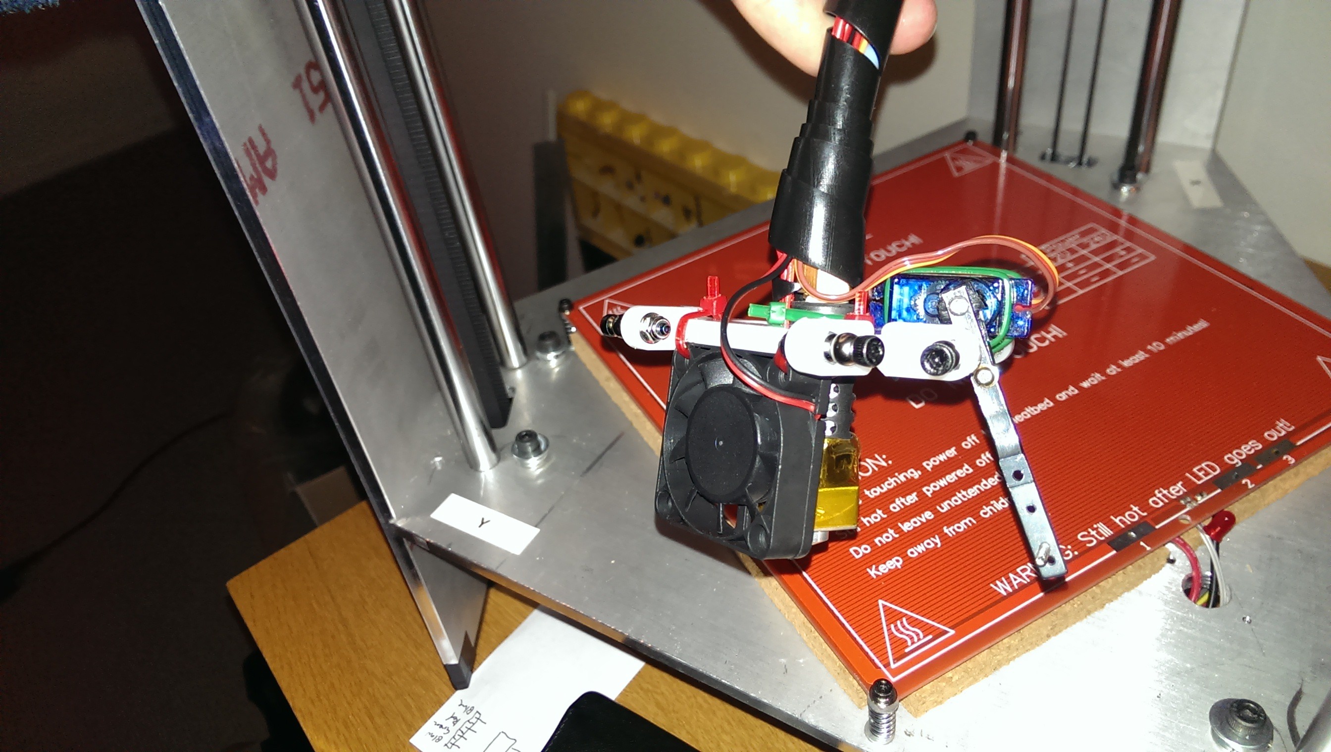
I originally wanted to have automatic bed levelling (tramming) and included a simple servo mounted micro switch. I ended up removing it because Marlin firmware didn’t have bed levelling for delta printers implemented yet. I ran some extra cables down to the hot end for an “always on” fan.
![Extruder cooling fan]()
Extruder cooling fan
-
Delta Mechanics
02/01/2017 at 08:32 • 0 commentsI wasn’t confident that I would be able to manufacture the three vertical sliders and end effector with the tools I had (to sufficient accuracy). I originally planned to have them printed using Shapeways. The price was going to be over AUD$100 (not including shipping). This was far out of my budget so I needed to find another way.
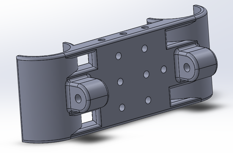
![Slider V1]()
Slider V1
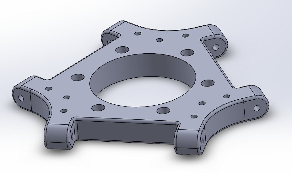
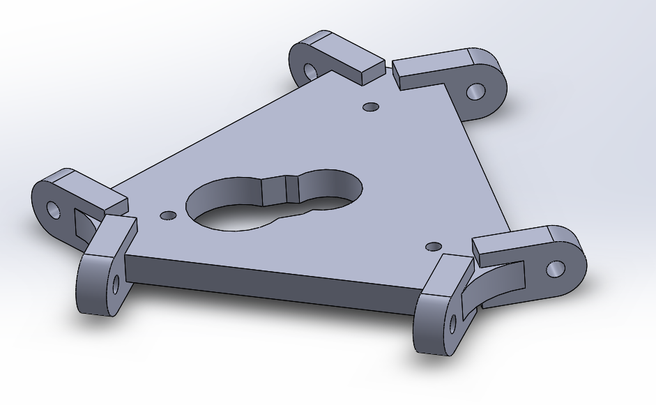
![Platform V1]()
Platform V1
I had another friend who had just joined a makerspace in Perth. He was showing me some of the trinkets and boxes he had made using their laser cutter. He offered to cut me some parts. I had to redesign the slider and platform (as I called it) to be made from acrylic/MDF sheet. I came up with the design below. Note that the little slots are for the cable ties to pass through and attach the linear bearings.
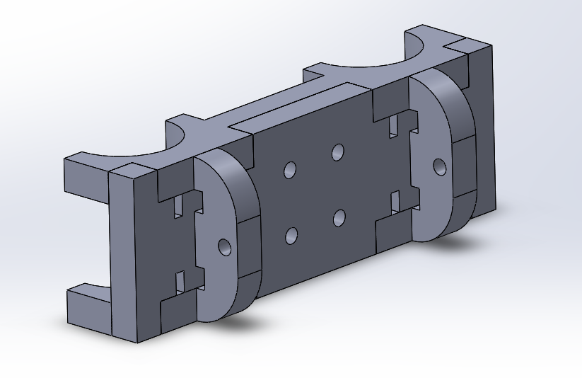
![Slider V2]()
Slider V2
![Platform V2 with groove for J-Head hot end]()
Platform V2 with groove for J-Head hot end
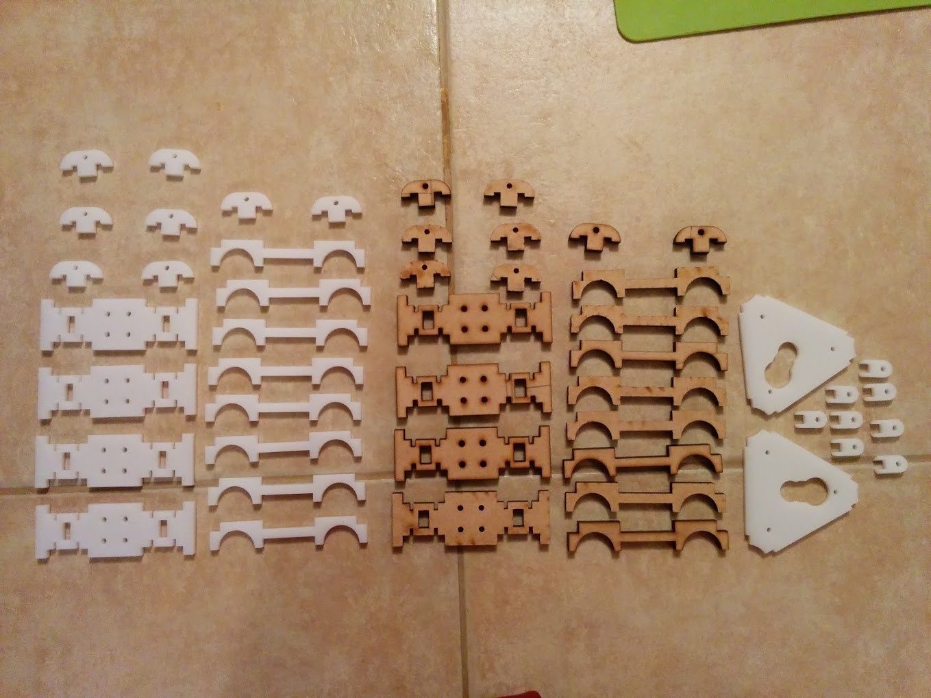
A short time later these arrived in the mail:
![So many bits to assemble!]()
So many bits to assemble!
He ended up cutting them from both materials and threw in a few spares. I decided to go with the MDF sliders as they would have a bit of give if things weren’t quite aligned. Armed with my bottle of CA glue, I began the assembly process.
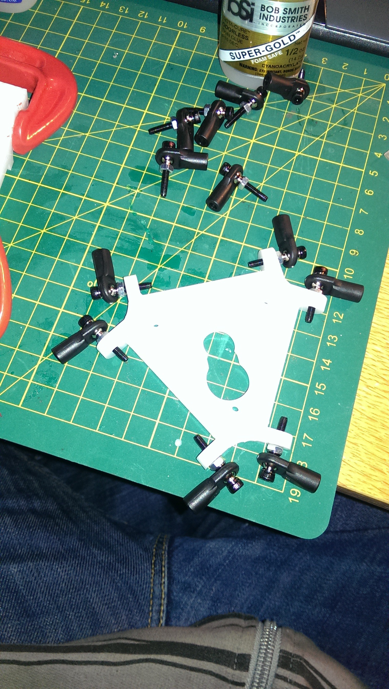
![Platform assembled]()
Platform assembled
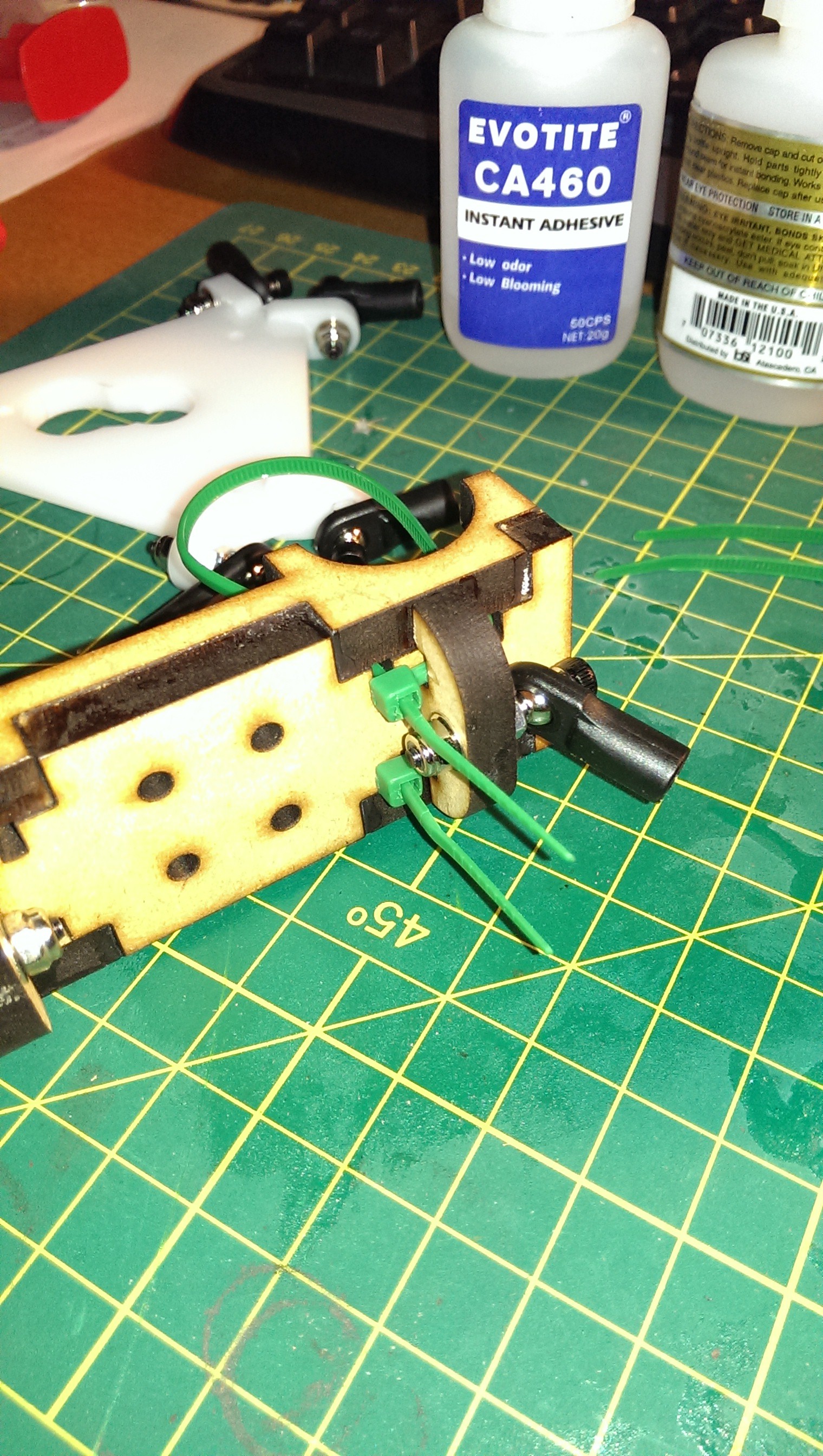
![Cable tie routing]()
Cable tie routing
![Test-fitting the LM12UU linear bearings]()
Test-fitting the LM12UU linear bearings
![One down, two more to go!]()
One down, two more to go!
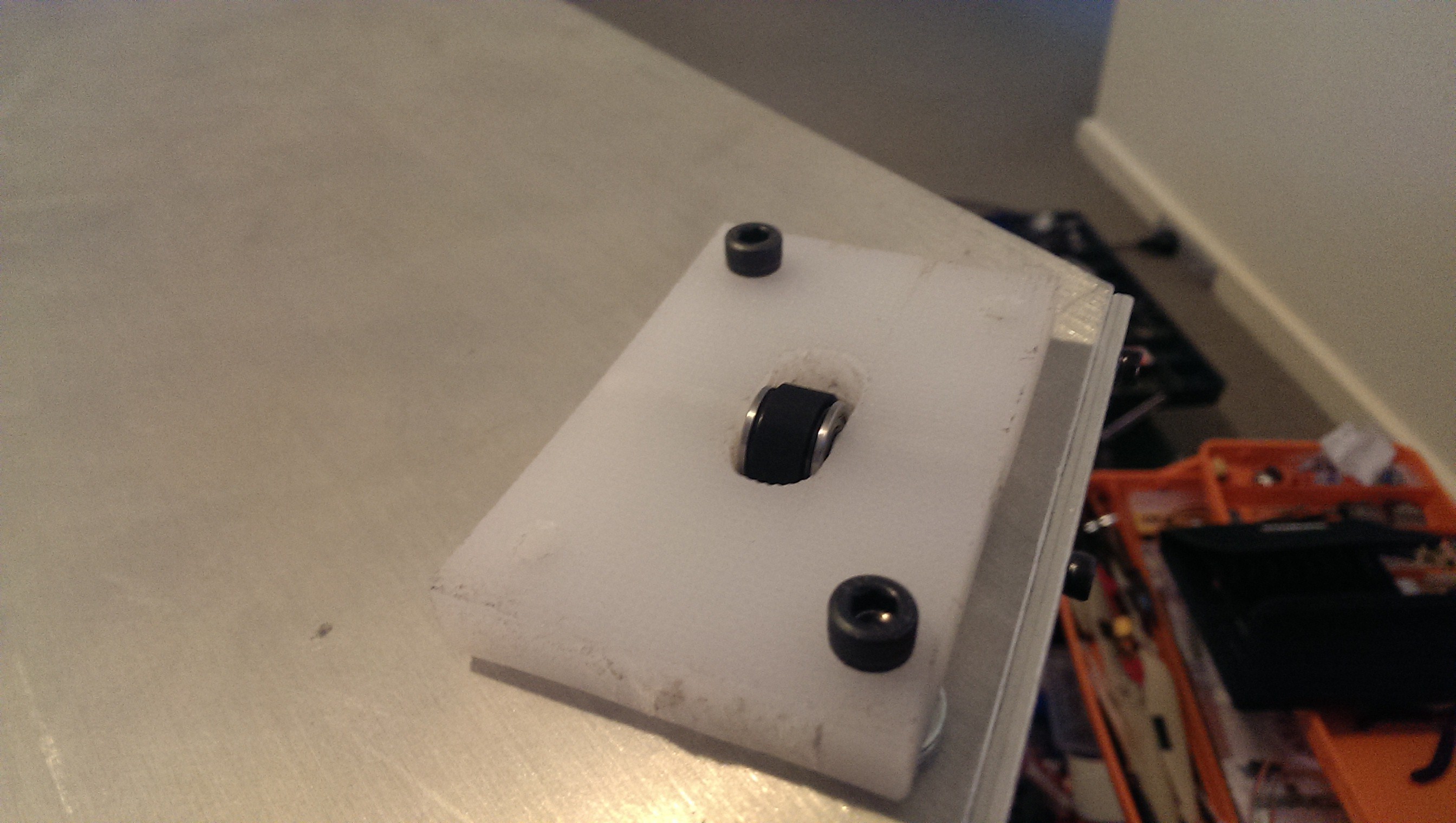
Only two of the four holes in the middle would be used for anchoring the GT2 belts. A simple anchoring method was to loop the timing belt over a protruding bolt. The bolts were aligned to ensure the belts would run straight between the motor pulley and idler pulley.
![Belt anchor bolts]()
Belt anchor bolts
The platform was cut with a tapered groove to allow the hot end to snap into. I was a bit off with my dimensions and needed to do some filing to get it to fit nicely. I had chosen the 5mm thick acrylic because that was the thickness required by the hot end groove.
![J-Head hot end fits!]()
J-Head hot end fits!
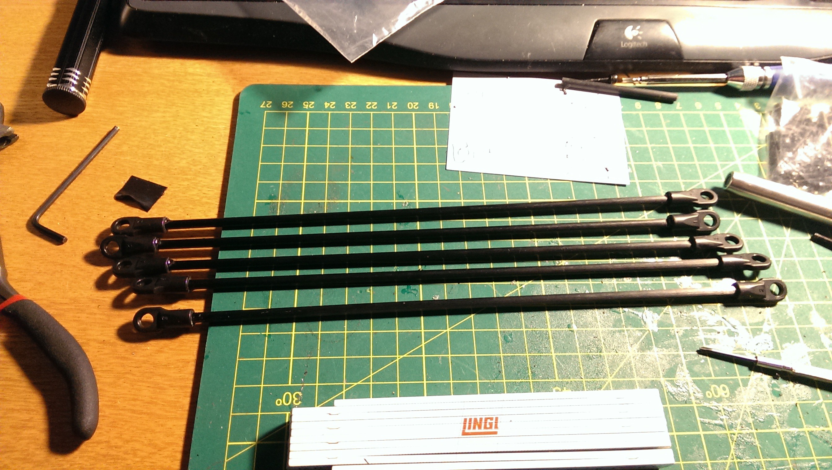
It was then just a matter of precisely cutting the carbon fiber tube to length and gluing it into the ball ends. They ended up more-or-less the same length. In hindsight I should have used a jig.
![“Precision” cut rods]()
“Precision” cut rods
I was now ready to assemble the delta mechanism and see how it all moved together.
![Ready to assemble]()
Ready to assemble
-
Motors & Belts
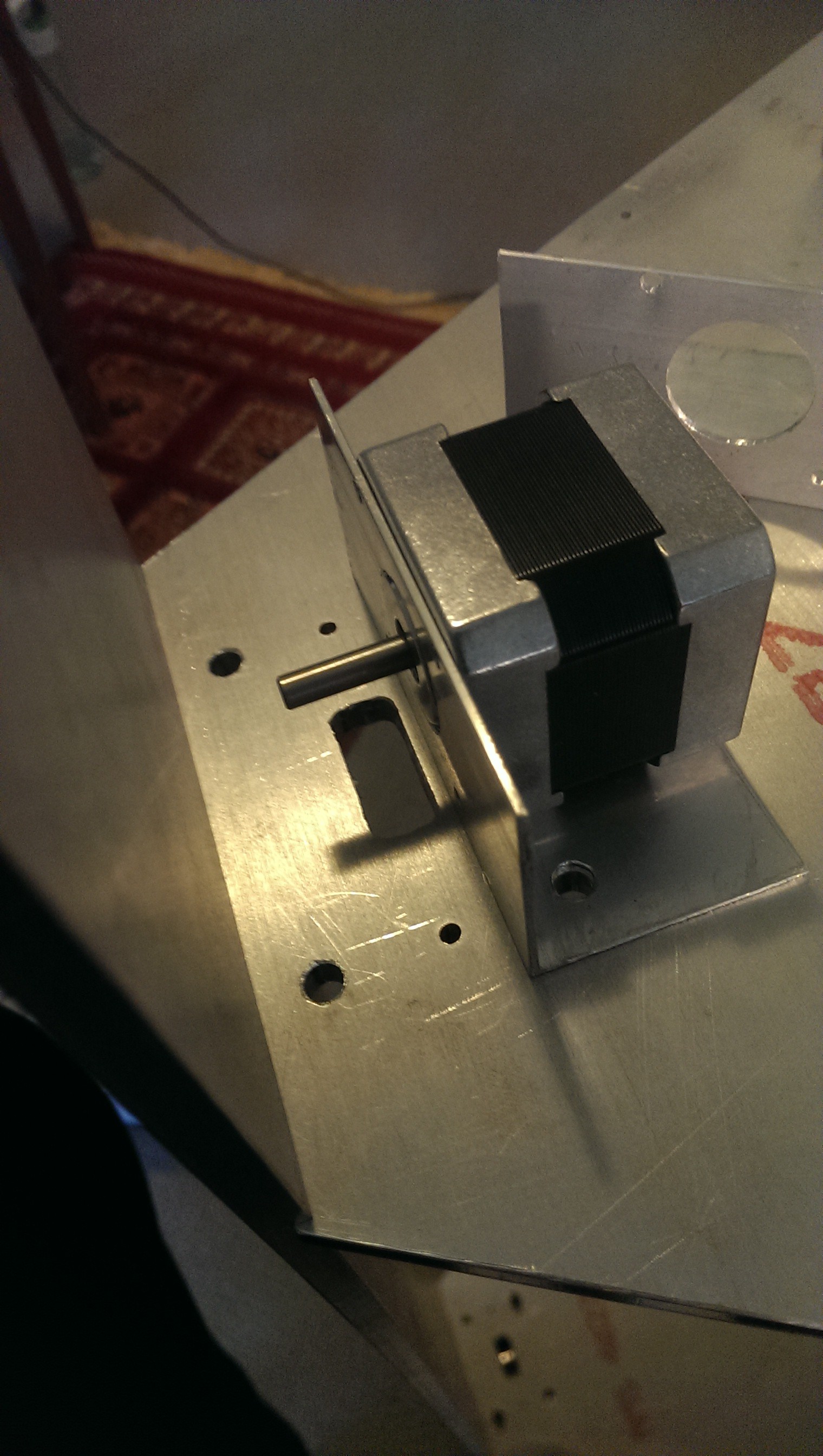
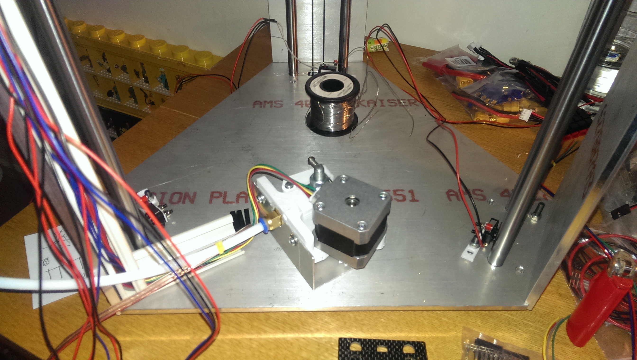
01/31/2017 at 11:06 • 0 commentsI bought some aluminium angle and manufactured simple brackets to hold the motors in place. I used the linear rail shaft mounting bolts to also mount the motor bracket. This kept the motors nicely aligned and reduced the number of fixings required.
![]()
Nema 17 bracket
![]()
Sharing the hole with the shaft mounting bolts
I used a portion of chopping board to mount the top idler pulley. The chopping board also shared mounting holes with the shaft mounting bolts below. I drilled a 5mm hole through the edge of the chopping board and slid a shaft in through some flanged bearings. I was really happy with this neat solution.
![]()
Idler pulley mounting blocks (two of four bolts installed)
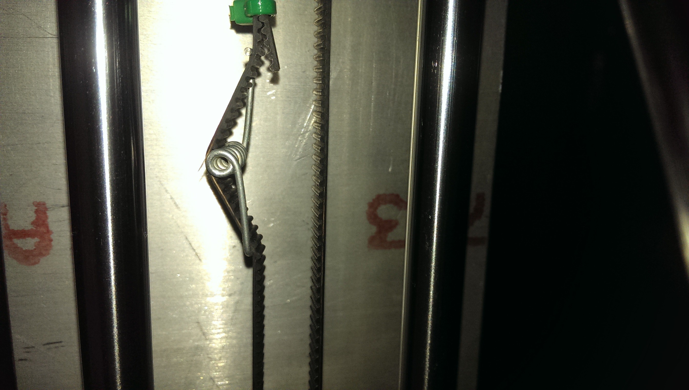
I had seen a few designs with fancy (and often intricate) belt tensioning mechanisms. I decided that I would not have any mechanical adjustments for the idler bearing and rely on an in-belt tensioning spring. I had seen many printers use this method and liked the simplicity. A few clothes pegs were sacrificed for their springs.
![]()
Clothes peg spring
Here is a test where I powered up a stepper motor for the first time.
It's alive!
The Greg’s Hinged Extruder was mounted upside down under the top plate using an aluminium bracket. I chose a mounting position that would allow for an unobstructed filament path.
![]()
Extruder Positioning
-
Frame
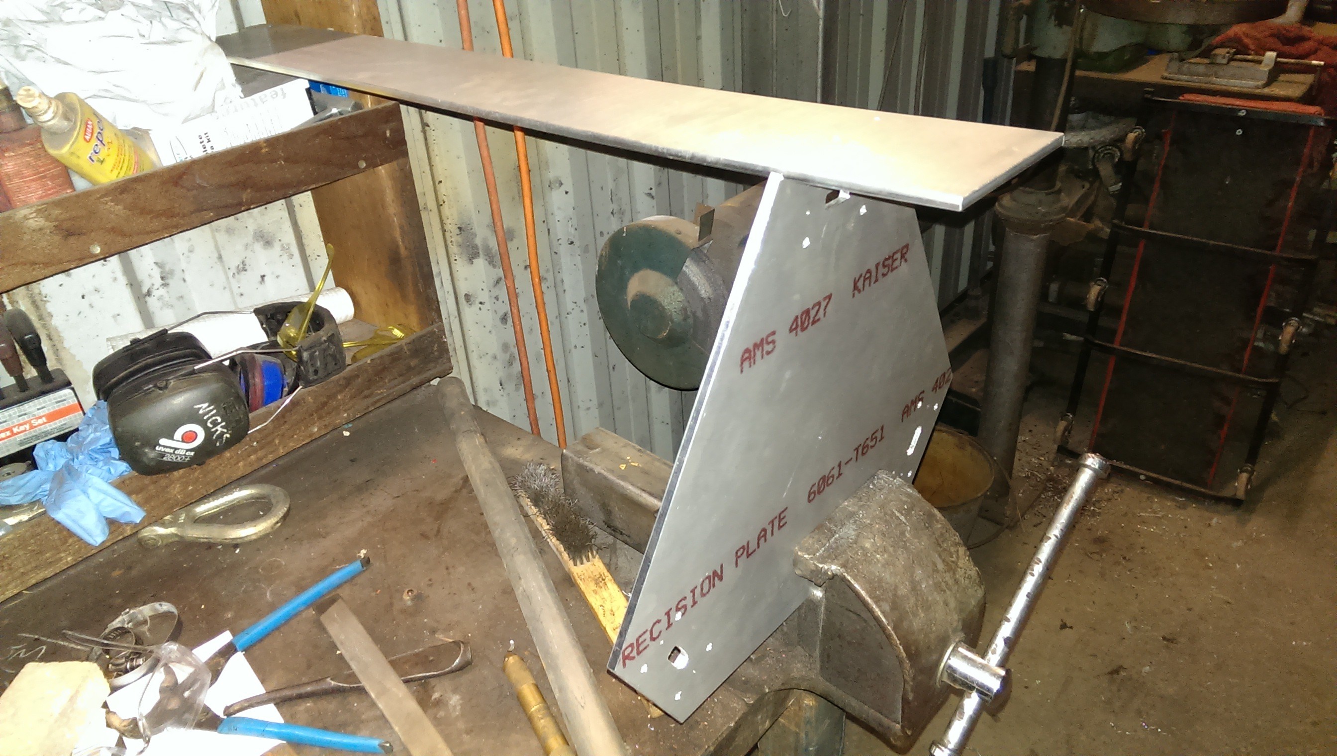
01/31/2017 at 10:08 • 0 commentsAfter redesigning the frame to be made entirely of 1/4” aluminium, I sent the CAD files through to my friend. Not long after that I received a very heavy delivery from him. All up it probably weighed about 12kg.
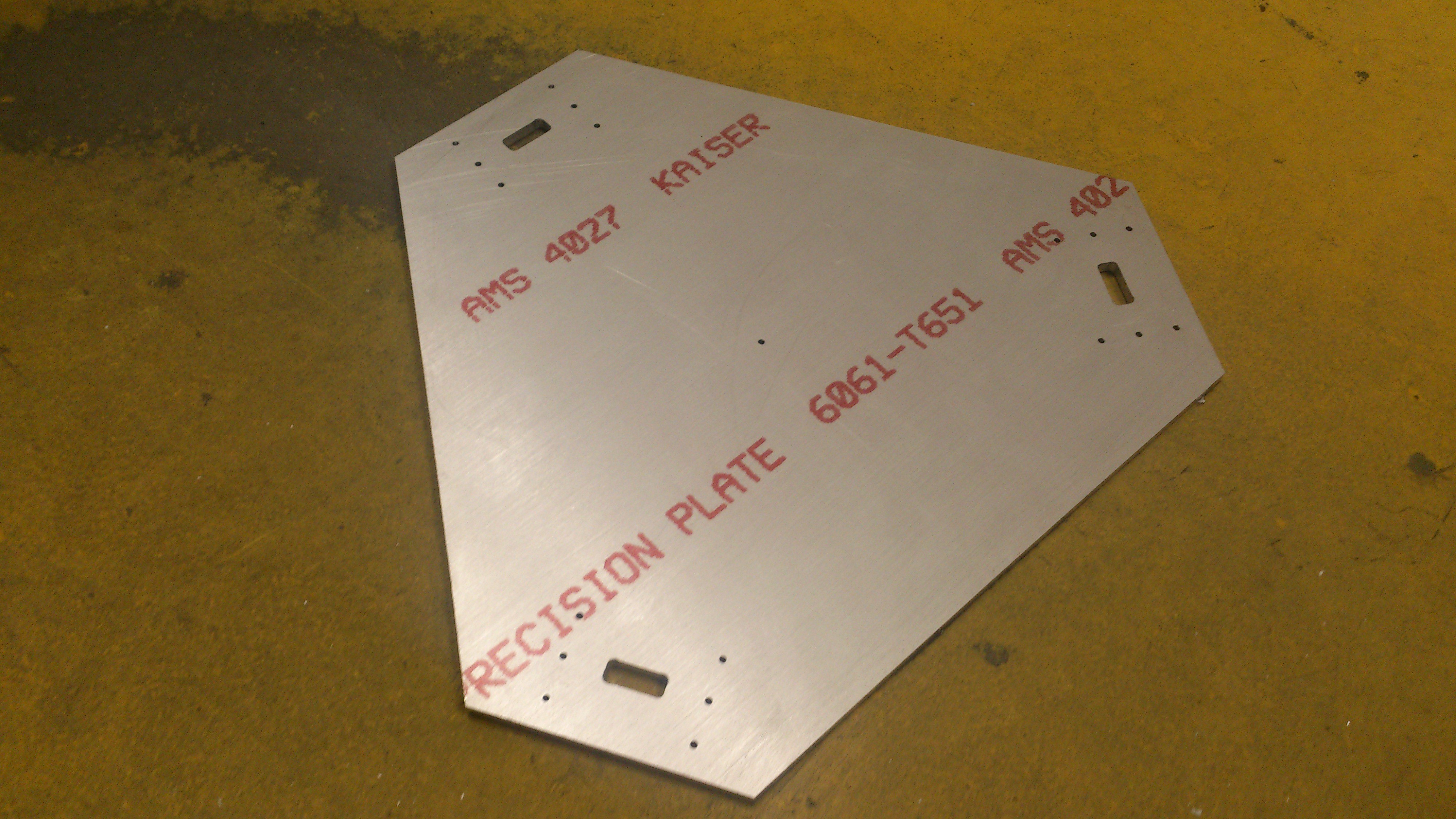
![This thing is huge!]()
This thing is huge!
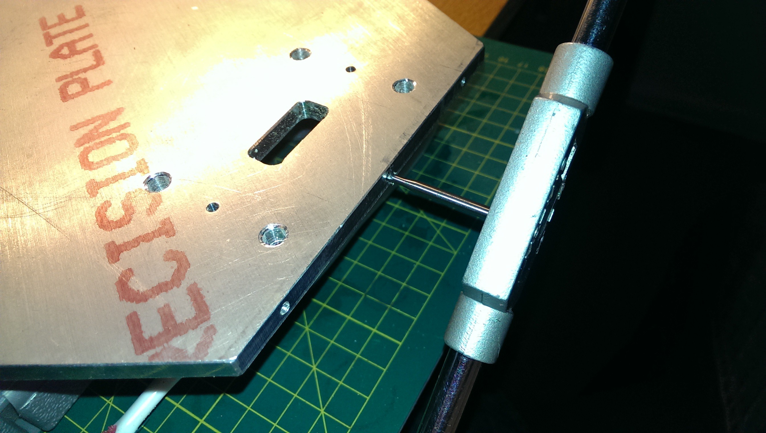
I had to somehow drill holes into the edge of the top and bottom plates. I decided that three M3 bolts per joint would be sufficient. My friend was able to mark pilot holes in the side plates so drilling them was straight forward. I placed them together in a bench vice and used the side frame to mark holes in the top/base. The holes were then very carefully drilled using a drill press. I still managed to snap off two drill bits in the new holes. Luckily they were both on the same edge so I was able to designate this as the “back” tower.
![Drilling holes in Dad's workshop]()
Drilling holes in Dad's workshop
![Careful tapping of the M3 threads]()
Careful tapping of the M3 threads
![I may have snapped off drill bits in some holes and had to re-drill just next to them]()
I may have snapped off drill bits in some holes and had to re-drill just next to them.
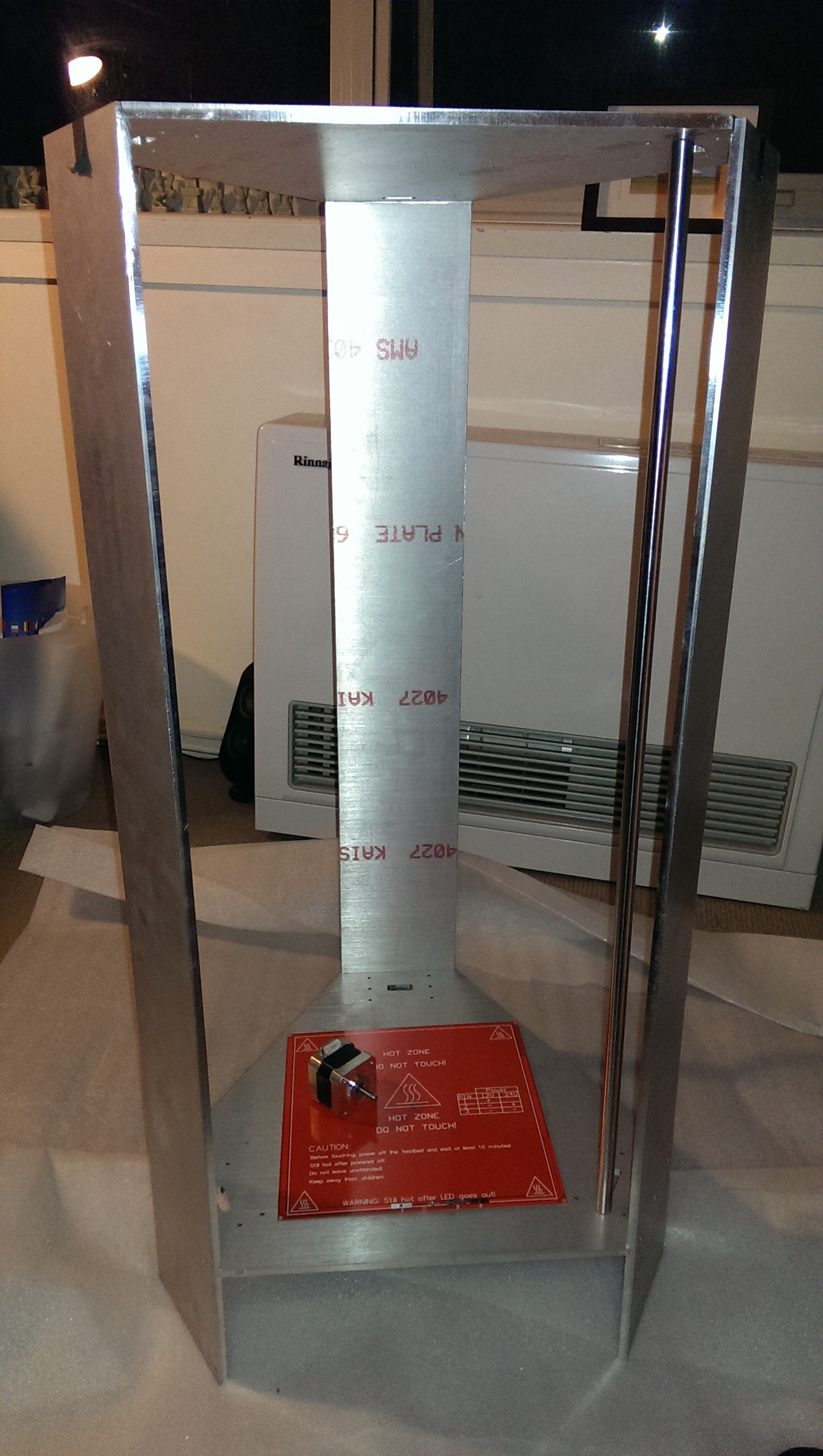
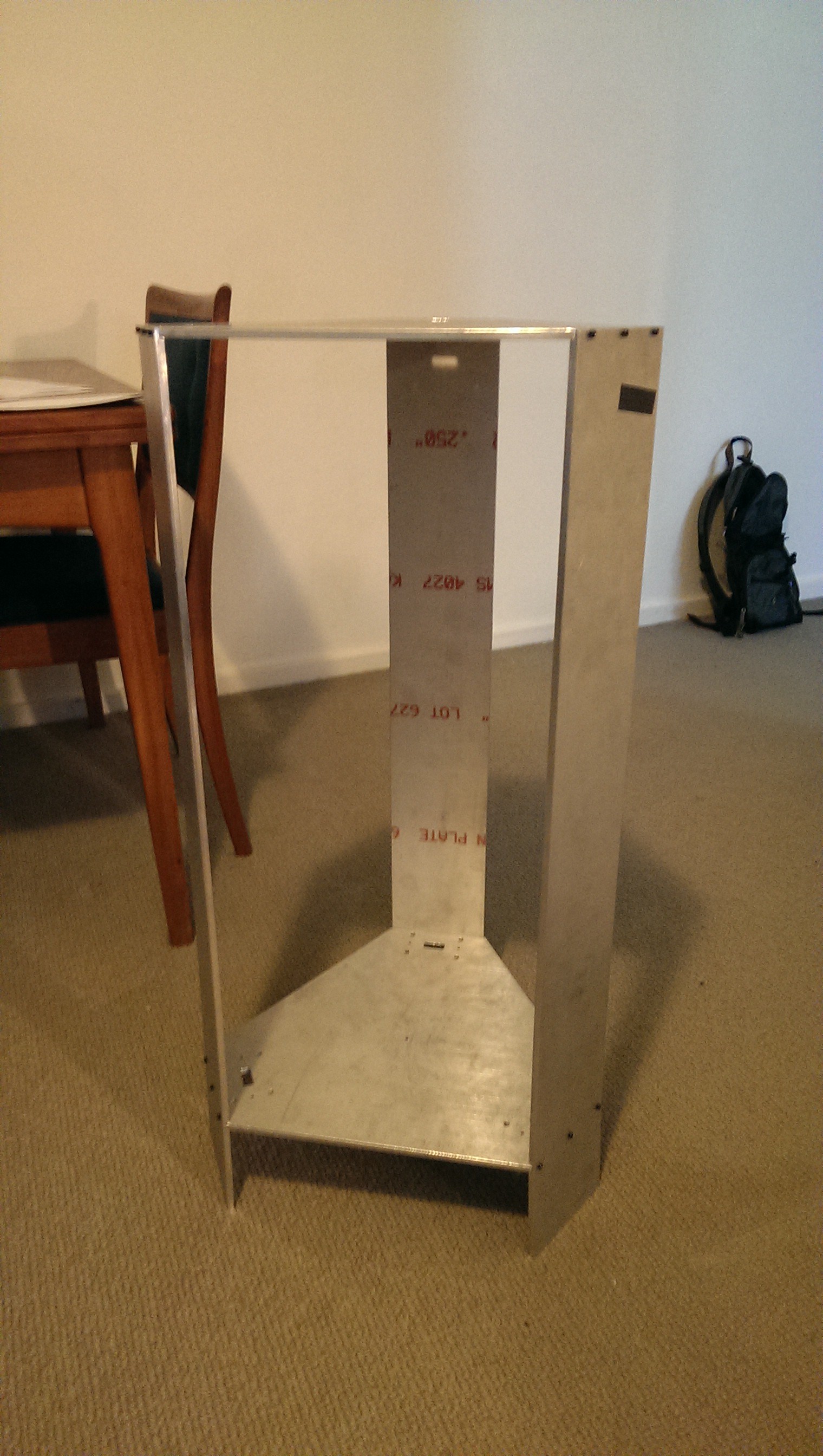
![]()
A very straight, strong and stiff frame.
As expected, when the grooves were slotted together, the frame pulled true. I was very happy with the rigidity and strength. It easily supported my full weight sitting on top and didn’t flex at all.
-
Purchased Hardware & Electronics
01/31/2017 at 10:07 • 0 commentsIn order to stick to my design goal of an AUD$1000 budget I decided to start a bill of materials spreadsheet. This would be a handy tool to keep track of budget and also allow me to show people if they wanted to try making something similar. Below is a list of the major components in the initial round of purchasing. Note that all prices are in Australian Dollars (AUD) and approximate at time of purchasing (Q1 2014). Also note that some of the eBay stores don’t stock these items anymore.
- RAMPS 1.4 Starter Pro Kit (eBay - LearCNC - $308)
- Complete electronics kit including RAMPS 1.4, LCD, Nema 17 motors, heated bed, GT2 belts with 20 tooth pulleys, thermistors and plenty of wires. I liked that this kit was complete and I didn’t have to source everything separately.
- 6 x SF12-700mm 12mm Hardened Round Shaft (eBay - silvers-123 - $106)
- I wanted a decent size build volume. Having 700mm shafts would give a maximum build height of around 350mm which I thought was plenty. Any longer would also make the printer more difficult to move around.
- 10 x 12mm LM12UU Linear Ball Bear Bearing (eBay - beautyzz2009 - $15)
- These were what most people were using on their linear shafts.
- 12 x 12mm SHF12 Linear Rail Shaft Support (eBay - may139188 - $30)
- To ensure the shaft is mounted strongly to the frame. I did think of just having a perfectly sized hole in the top and bottom plates (for the shaft to sit in) but that would be a pain to dismantle/maintain.
- 10 x Flanged Ball Bearing F685ZZ 5*11*5mm (eBay - angelinvestment2010 - $10)
- Placing two flanged bearings together (facing each) other is a very cheap and easy way to create a pulley. I chose the 11mm diameter because it almost matches the diameter of the 20 tooth GT2 pulley teeth. This meant that the belts would remain parallel and aligned through the whole range of movement.
- J-Head Hot End for 3mm Filament (eBay - geeetech-official - $33)
- This style of hot end seemed to have decent reviews for the price.
- Greg’s Hinged Extruder Kit (eBay - vpeters1984 - $30)
- This was to be the only 3D printed part that I needed to buy. This was the most widely praised reliable extruder out there. This guy was selling complete kits which meant that I didn’t have source any of the nuts and bolts separately.
- 4m GT2 Timing Belt and extra GT2-20T pulley (eBay - LearCNC - $20)
- I needed some extra length as the three axis are much longer than regular cartesian printer’s axis.
- Pack of 12 Traxxas Rod Ends Large with Hollow Balls (eBay - rchobbies4life - $14)
- These were popular cheap and reliable ball joints for delta printers.
- 4mm x 750mm Hollow Carbon Fiber Tube (Hobbyking - $9)
- I chose this diameter because it fit snugly inside the rod ends (once they were drilled out to 4mm).
- Cork Pot Placemat and Chopping Board (Local discount shop - $9)
- The placemat was for insulating the heated bed. The intention of the chopping board, made from some kind of nylon, was for manufacturing small brackets and mounting blocks.
- 200mm x 214mm Borosilicate Glass Bed Plate (eBay - LearCNC - $26)
- I really liked the idea of printing on glass rather than on the PCB heated bed. Having a perfectly flat glass plate would make calibration and first layer adhesion easier (this proved true).
- 1m PTFE Tube for 3mm Filament (eBay - LearCNC - $13)
- To achieve fast print speed and acceleration, I decided to use a bowden tube system for getting the plastic to the hot end. This meant that the print head would be nice and lightweight.
- Aluminium 40mm x 40mm x 1m L section (Bunnings Warehouse - $11)
- For manufacturing motor brackets.
- Push Fittings for bowden Tube (eBay - sellerbible - $8)
- For spares.
- Spiral Cable Wrap and Self-Adhesive Ducting (Bunnings - $30)
- I wanted the printer wiring to be very neat and tidy. I’d seen many scratch-built printers with wiring all over the place and not much thought given to smart cable management. The cable wrap would neatly bind the hot end wiring to the bowden tube. The ducting would be used for the wire bundle going from the base of the printer to the top.
- 12V 20A Switching Power Supply (eBay - zhengzheng2011 - $20)
- Just a generic cheap power supply. Sufficient for my purpose.
- IEC13 Socket with Integrated Fuse (Jaycar - $8)
- The intention here was to make a cover to go over the end of the power supply that safely contained all mains wiring. I found this neat little socket with fuse and figured it would be a nice neat solution. Also, by not hard wiring the mains lead, I would not have a cable dragging everywhere and getting caught while working on or moving it.
- Assorted metric nuts, bolts, washers etc. (Hobbyking)
- I tried really hard to ensure that most fixings on the printer would have M3 thread, except the shaft mounting bracket bolts.
- RAMPS 1.4 Starter Pro Kit (eBay - LearCNC - $308)
-
Design
01/31/2017 at 10:01 • 0 commentsFirst, I needed to decide the basic geometry for the printer. I drew up a rough model and decided on a delta radius of 170mm and an arm length of 250mm. This would give enough reach and resolution to print on a standard 200mm x 200mm MK2B PCB heated bed. I did investigate a circular heated bed but the cost was significantly higher at the time.
![Geometry Design]()
Geometry Design
My original design composed of top and bottom sheets of MDF or Aluminium with some 4040 extrusions as a frame. This would provide high rigidity and allow the use of thin linear rails.
![Printer V1]()
Printer V1
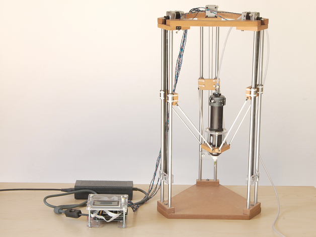
I decided I didn't like the design and started googling for more ideas. I stumbled upon this:
![Inspiration]()
Source: http://www.3ders.org/articles/20130915-build-your-own-ceramic-delta-3d-printer.html
I found the printer in the above blog featured a very simple frame design. It consisted of wooden (MDF) frames top and bottom with linear rails performing both structural and functional roles. It used widely available LMxxUU bearings and simple RC car ball joints. This design was very simple and elegant. I found some 12mm shaft mounts on eBay and figured that they would help to hold the linear shafts in the MDF nicely.
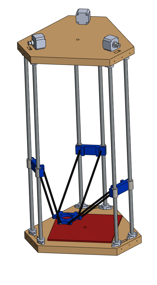
My first ‘complete-ish’ design had the motors at the top. This was to minimise wiring going from the power/control circuitry down the sides of the printer. It had a few flaws that I didn’t like:
- There was nowhere to run the wires as the linear bearings needed clearance.
- The power supply would need to be at the top so the mains lead might get in the way.
- It would be quite top heavy.
- Rigidity would be a problem.
![Printer V2]()
Printer V2
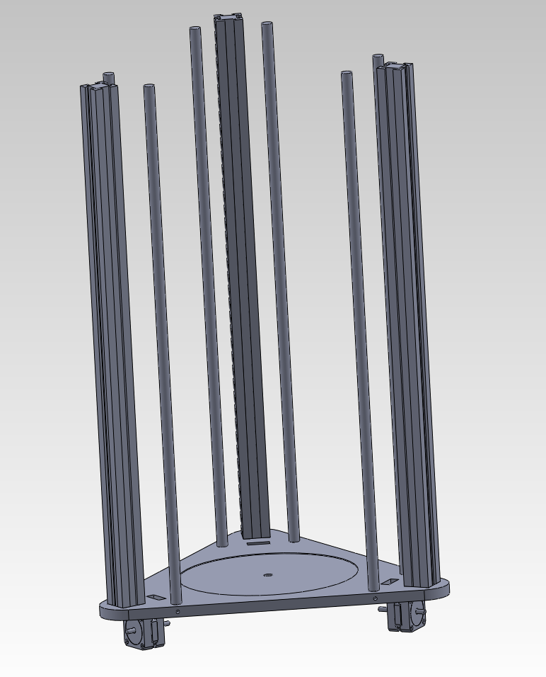
I had some thoughts that the frame might not be rigid enough as MDF can go soft when subjected to flexing (e.g. from transporting the printer). I changed my design a few times and ended up adding acrylic sheets to the sides. This would increase frame stiffness and give somewhere to run the wiring. I also decided to have the motors, power supply and control board tucked neatly underneath.
![Printer V3]()
Printer V3
I had read many times that to achieve good accuracy, the tower positions must be perfectly spaced. I had planned to cut the MDF sheets by hand so decided that a jig would be required for decent tower spacing. Luckily, I had a friend who worked at a manufacturing house with a large table router. I sent through my CAD file and a few days later was holding on to a heavy 1/4” (6.35mm) sheet of CNC cut aluminium.
![Drill Jig Design]()
Drill Jig Design
![Hefty Drill Jig]()
Hefty Drill Jig
I was expecting it to be thinner and I jokingly said to him that I “might as well use it as the frame instead” to which he replied “I can cut you another one tomorrow if you’d like, and any other bits you need”.
I excitedly said “yes” because aluminium would be much better than MDF. I then did another iteration of my CAD design with new side frames. The side frames would have a groove milled into them so that I was guaranteed that the frame would “pull true” when assembled. This design decision was fundamental in achieving a very straight and rigid frame. It ultimately resulted in an easy to calibrate printer.
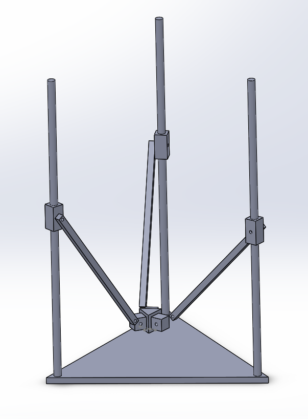
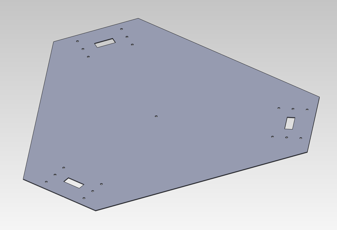
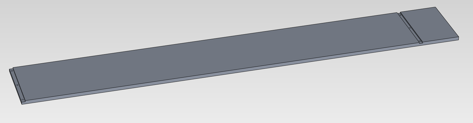
![Side Frame]()
Side Frame
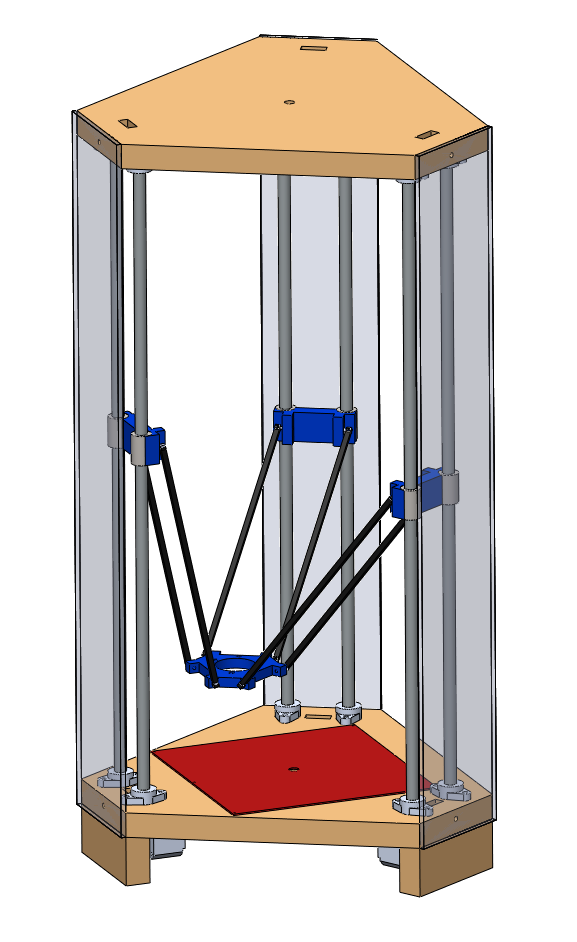
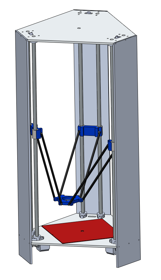
![Printer V4]()
Printer V4
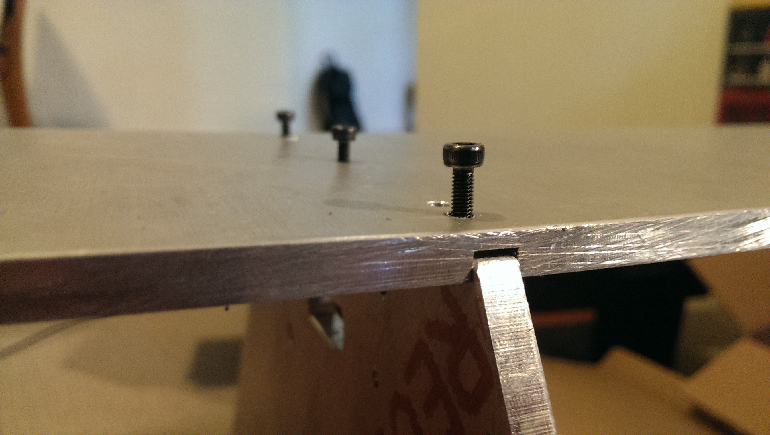
Due to the thickness of the aluminium sheet I planned to drill and tap a number of M3 threads into the edge. The side frames would then be able to be bolted straight to the top and bottom plates without the use of brackets. This would be a very neat and tidy solution and hopefully strong enough.