Close
0%
0%

Hacking the Zytek 55kW EV drivetrain

The Zytek drivetrain has a built in inverter with proprietary CAN interface. This project will replace just the microcontroller board.

Similar projects worth following
This drivetrain is available pretty cheap from EVwest (they may offer a discount since it's non-working without a CAN controller.) Inside the motor casing there is a very beefy motor controller with 800A IGBT module, filter capacitors, isolated gate drivers, isolated current sensors, 12V isolated DC-DC converter, and a controller board with proprietary CAN interface. We can't interface with the controller board without reverse engineering the CAN protocol. This is possible, and I've been told others are working on it.
However, we should be able to replace the controller board quite cheaply using an InstaSpin Launchpad from TI coupled to a custom interface board. This can then run custom software and interface directly to throttle and regenerative brake signals and provide motor data to a cabin display.

I've been doing some work on this project, haven't gotten around to documenting it, so here is a run down:

- Talked to a group of people who have an electric smart car and are working on reverse engineering the CAN protocol, see http://illuminatimotorworks.org/blog

- I took a stab at it myself with the CAN datalog files they have. Could get the DC/DC converter operating but not the motor spinning. I decoded a couple of the CAN packets and worked out the checksum byte (it's "CRC-8/SAE-J1850" btw) and the structure of a couple of the packets but there are too many unknowns. Right now I've put this in the 'too hard' basket, may revisit. Perhaps I'll head over to St. Louis for one of their hackathons.

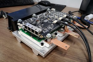
- Finished laying out a PCB for my replacement control board (using a TI Piccolo launchpad running InstaSpin much like my ebike controller) Got this board spun and assembled.

- Attached the control board to the gate driver board and current sensors, got the motor analysed and spinning with sensorless FOC. Messing around with firmware examples I got it working with the position sensor, although having trouble with the transition from sensored to sensorless.. work in progress.

Pictures are fun, so here is the assembly:
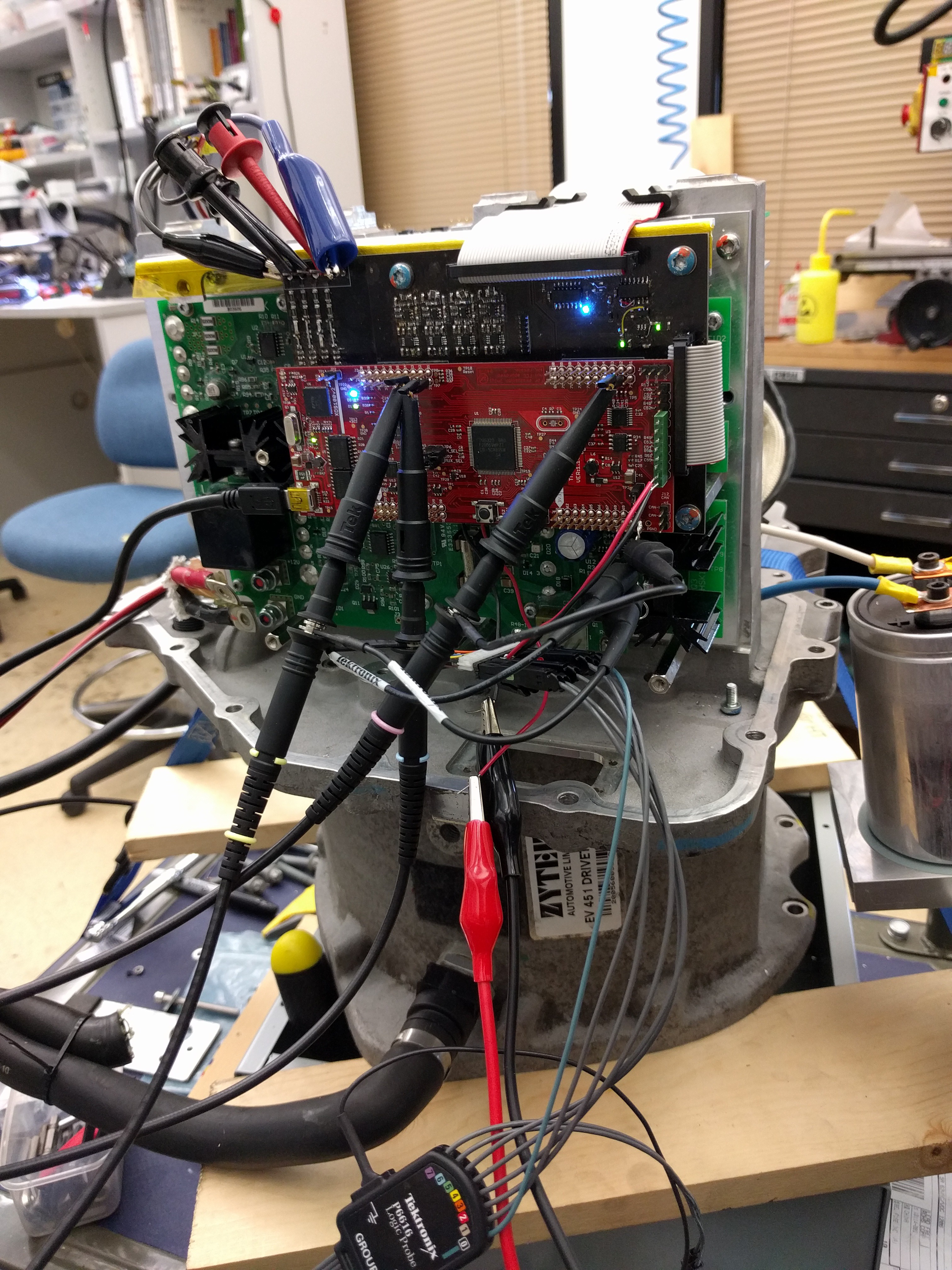
I'm keeping my github up to date with hardware and software files. will transition the Altium files to CircuitMaker shortly.

https://github.com/jarrod89/ZytekMotorController

  • Gate driver interfacing

    Jarrod09/28/2016 at 08:50 12 comments

    After much probing and a few datasheets I've got a pretty good idea of how the gate drive board works and what it's pinout is!

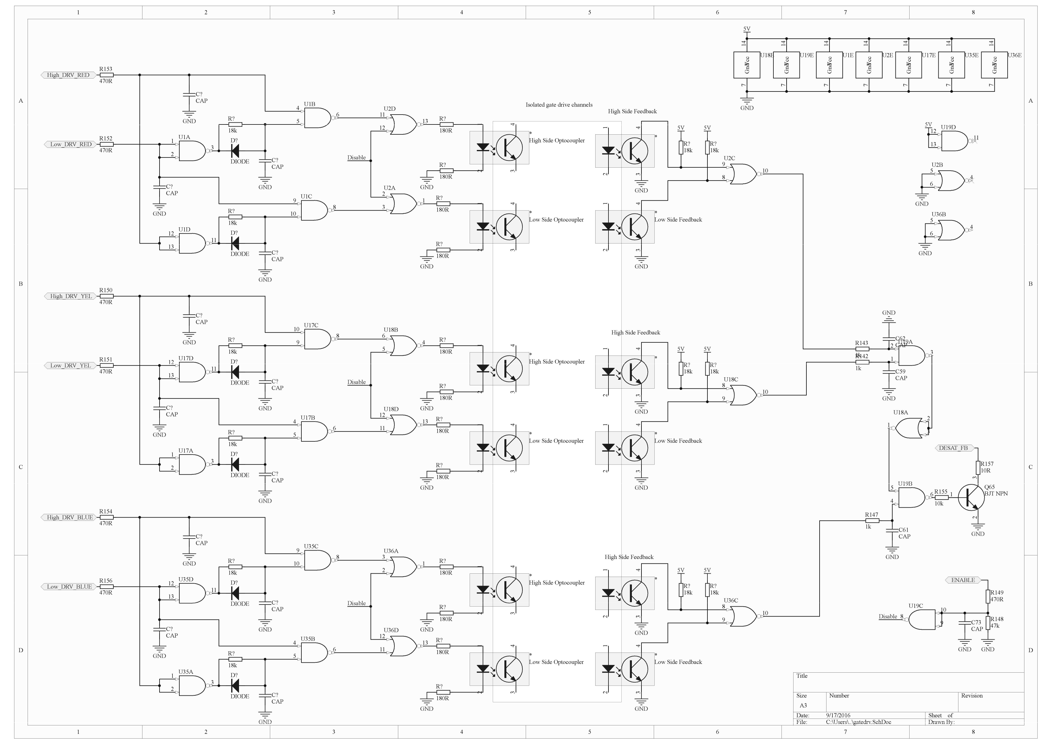
    It looks like they put a fair bit of logic on the gate drive board mainly to ensure shoot-through never occurs. Shoot-through is when both switches in a half-bridge (ie one half of a H-bridge) turn on at the same time, causing excessive current as the rail is essentially short circuited. As you can imagine this is pretty destructive, so they don't want any noise from that long ribbon cable causing false pulses into the gate drives. The on board logic ensures only one switch in each half bridge can be activated at any time plus it inserts a dead-time between them. A master enable line can also shut down the entire circuit.

    In the middle is the isolated (by optocoupler) gate driver stage. I didn't bother tracing this as it's quite complex and should behave predictably given how clear the function of the above circuitry is. Also not shown is the isolated dc/dc +/- supply for each gate driver, these all run off the 12V rail. and are rated at 2.5W.

    On the right is feedback for IGBT desaturation, this is a common function in IGBT drivers where the Vce voltage is monitored while the switch is on, if the current becomes greater than the bipolar transistor saturation current, it will desaturate, enter the transistors linear region and Vce will rise, triggering the protection circuit. This is an effective over current protection mechanism as long as the switch is turned off quickly enough (full current with a large voltage burns a LOT of power, think >10KW as heat - the IGBTs can only dissipate this for so long..)

    All 6 desat outputs are effectively OR'ed together (if you remember your boolean gate transforms) and sent back to the control board with an open collector output.

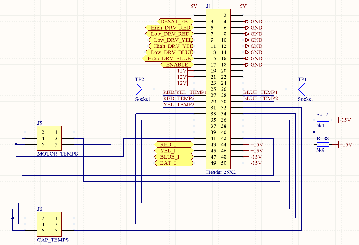
    The connector pinout looks something like this:

    Not shown is an on-board +/-15V power supply and the current sensor connectors. This means the board requires only 12V and 5V input rails.

    This all should be enough info to start designing a controller board.

  • Zytek hardware

    Jarrod09/24/2016 at 21:43 0 comments

    Since this is the first project log, I'll 'briefly' go over the motor and driver as I tear it down.

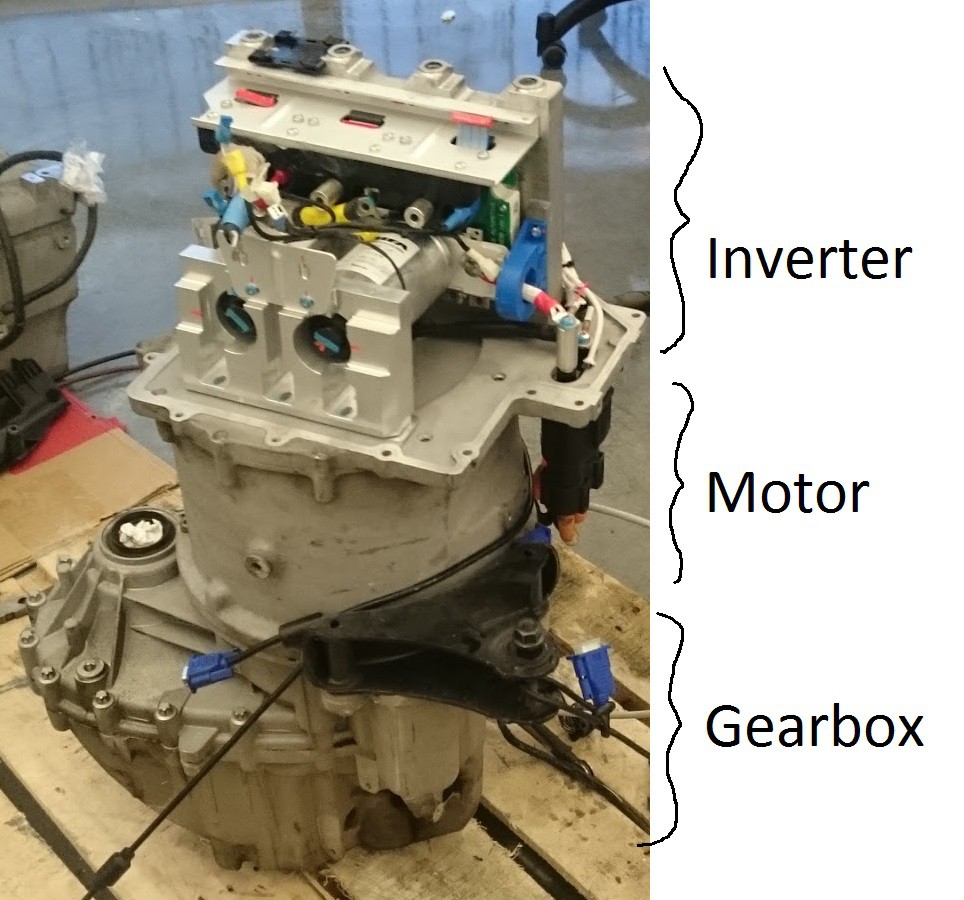
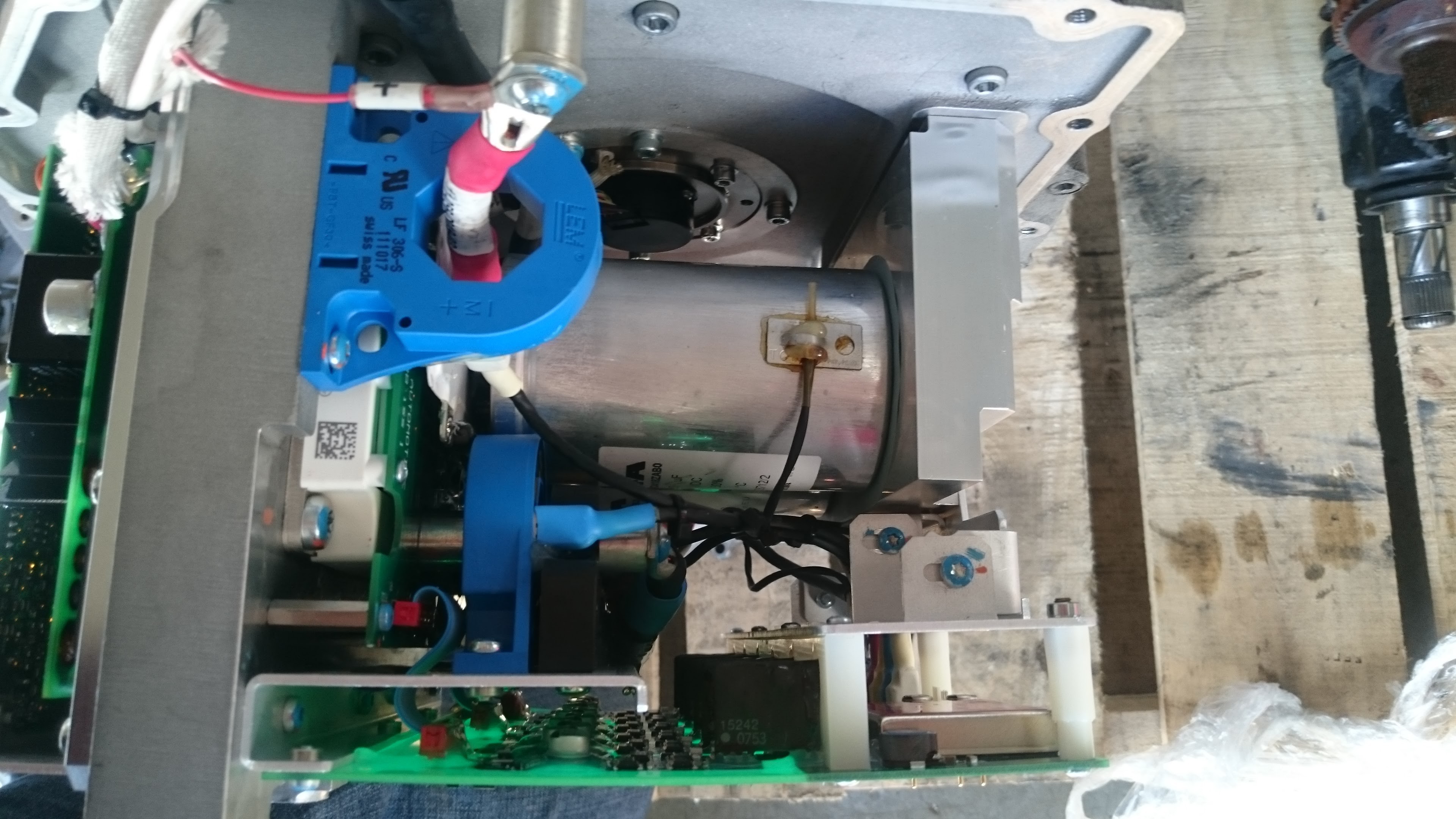
    With the inverter lid popped off it's a bit clearer where the actual motor is. (it's smaller than the inverter!!)

    in that picture I've already removed the gate drive board.

    A couple of better closeups of the inverter layout:

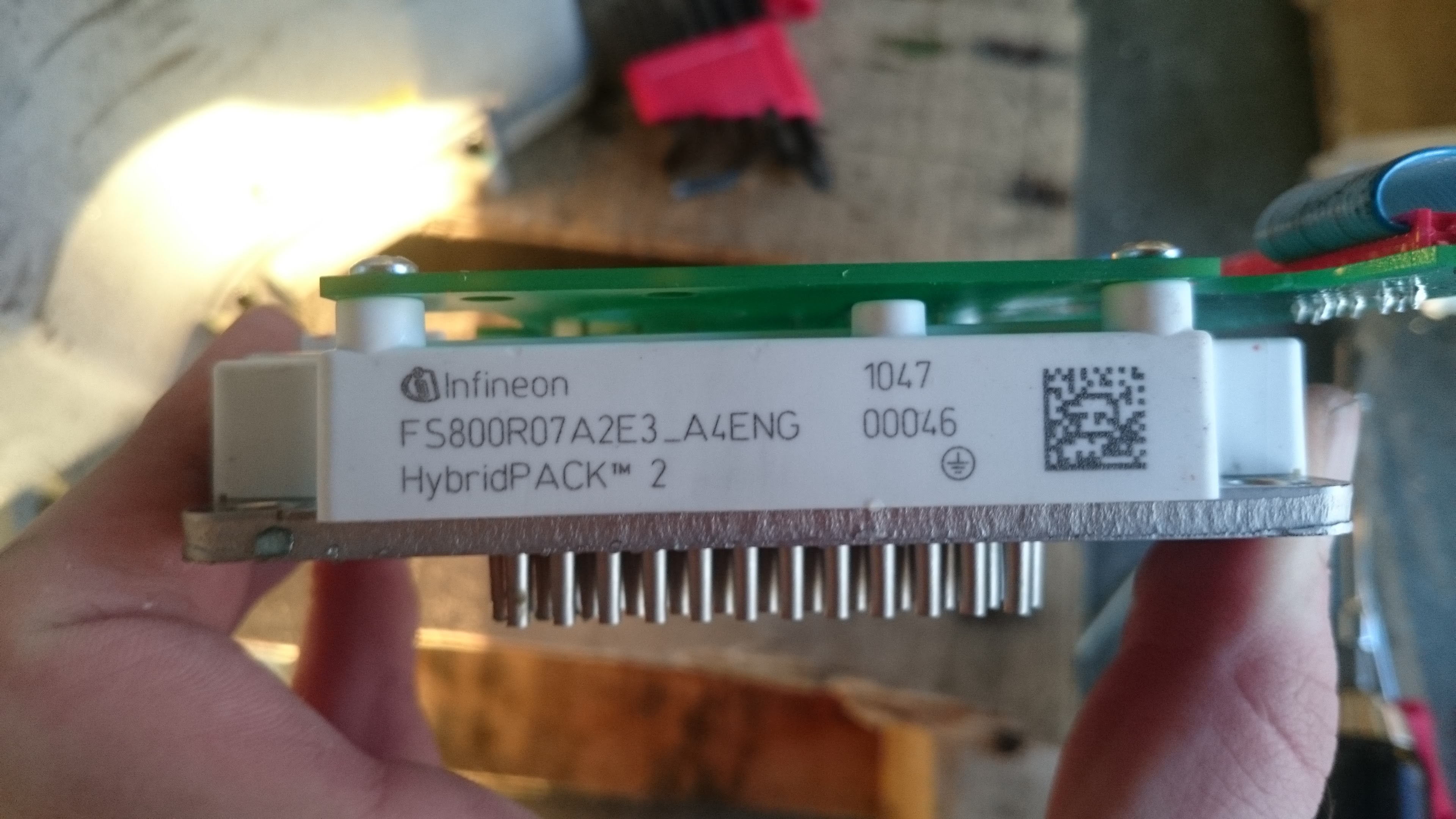
    The inverter (called so because it takes DC from the battery and generates a 3-phase AC current) consists of various PCBs for controlling the main insulated-gate bipolar transistor (IGBT) module:

    It's a watercooled beast! rated to 800A, 650V per switch. the watercooling channel is built into the motor case casting and it shares coolant flow with the motor.

    This module is an arrangement of 6 transistors, two on each motor phase. the 'highside' transistor connects the motor phase to the positive terminal of the battery, the low side connects it to the negative. The high side and low side are turned on periodically (NEVER at the same time as this would short out the battery) at 10khz with an average 50% duty cycle. by controlling the duty cycle of each phase, the motor can be provided with the required AC signal and driven in any direction with controllable speed and torque. The inductance of the motor (about 170uH) provides some electrical filtering which limits the current ripple through the switches.

    Two 1800uH 450V capacitors filter the current spikes on the input DC bus. They are mounted to a heatsink and have thermal sensors, so they clearly get hot. Which is no surprise given they are electrolytic caps, and would be very lossy at 10khz. kinda funny design choice there. I'll go on a rant about the 10khz switching frequency in a later post...

    To properly control the torque, a current feedback loop is required, a current transformer (the blue ring things) on each motor phase plus one on the battery terminal are used (4 total.) These transformers are also able to measure DC current as they combine both a transformer winding and hall effect sensor.

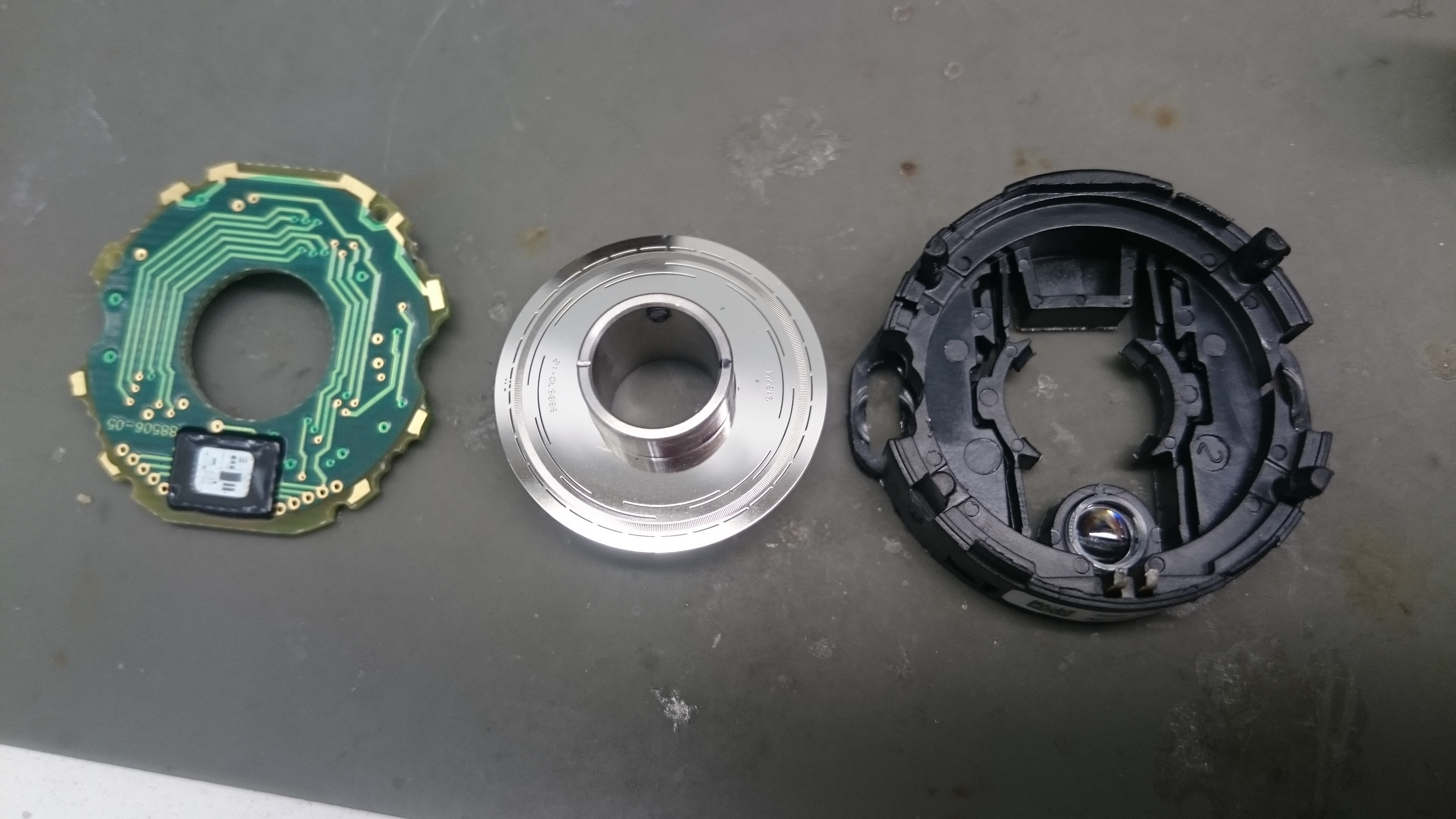
    The generation of AC waveforms must by synchronized with the motor rotation, this is done with an optical shaft encoder, a pretty cool little device in it's self. It contains a stainless steel disk with tiny holes cut in it, this acts as a photo-interrupter with an LED on one side of the disk and a small photo-sensor IC on the other. The encoder outputs a tachometer pulse, a six-step signal (same as you get out of the three Hall sensors on a common BLDC motor) plus a high-resolution quadrature signal (hundreds of steps per electrical period)

    The electronics are actually powered from the car 12V battery system (which also powers the cars lights and aux systems and is connected to the car chassis) so for safety the high voltage 200-400VDC battery connected circuit must be isolated from the 12V system, so all gate drive and sense circuits need to use optocouplers or transformers to achieve isolation and transmit power. The inverter also contains a couple of 400V->12V DC-DC modules which use transformers for isolated power to charge the 12V battery system.

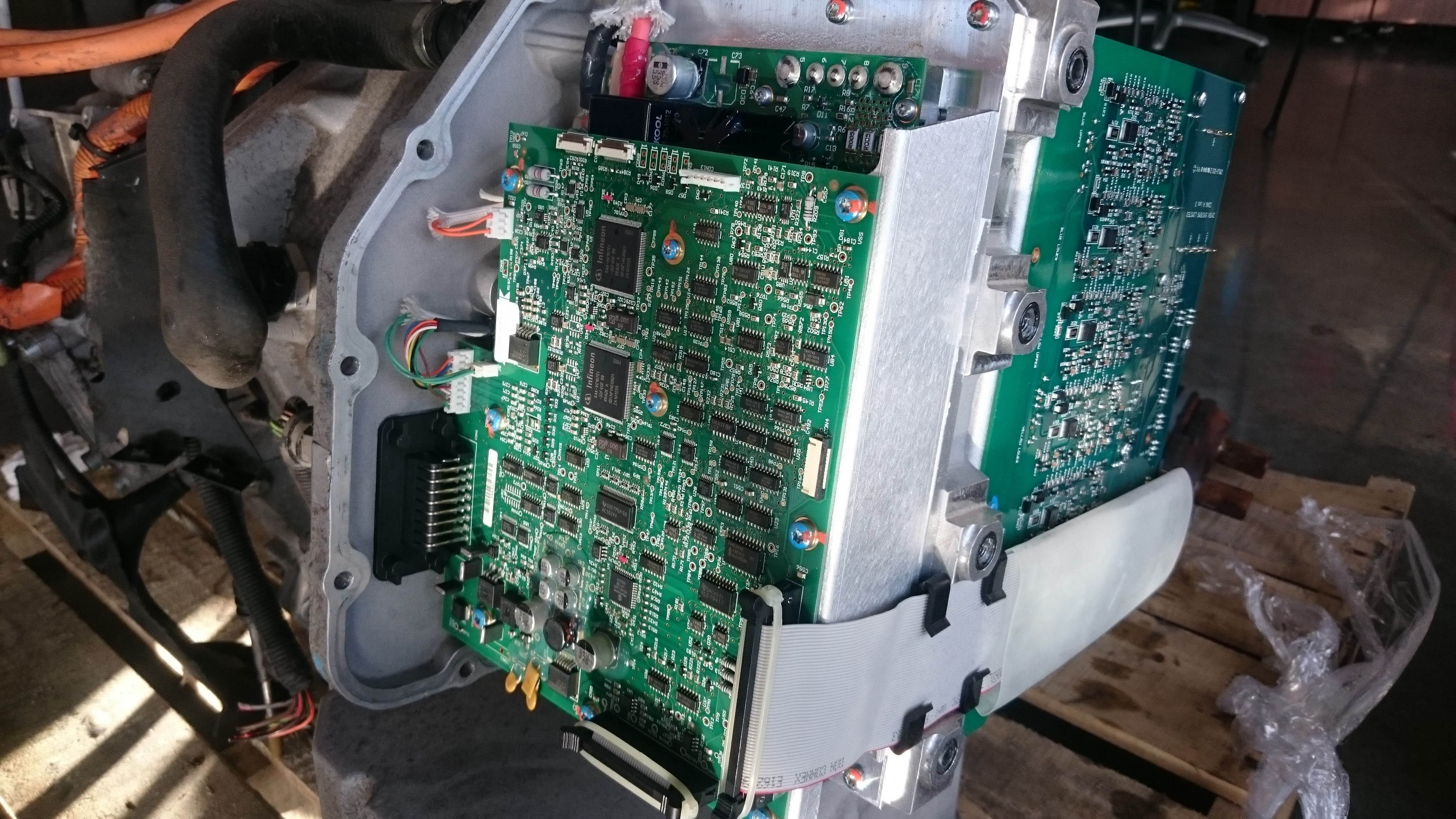
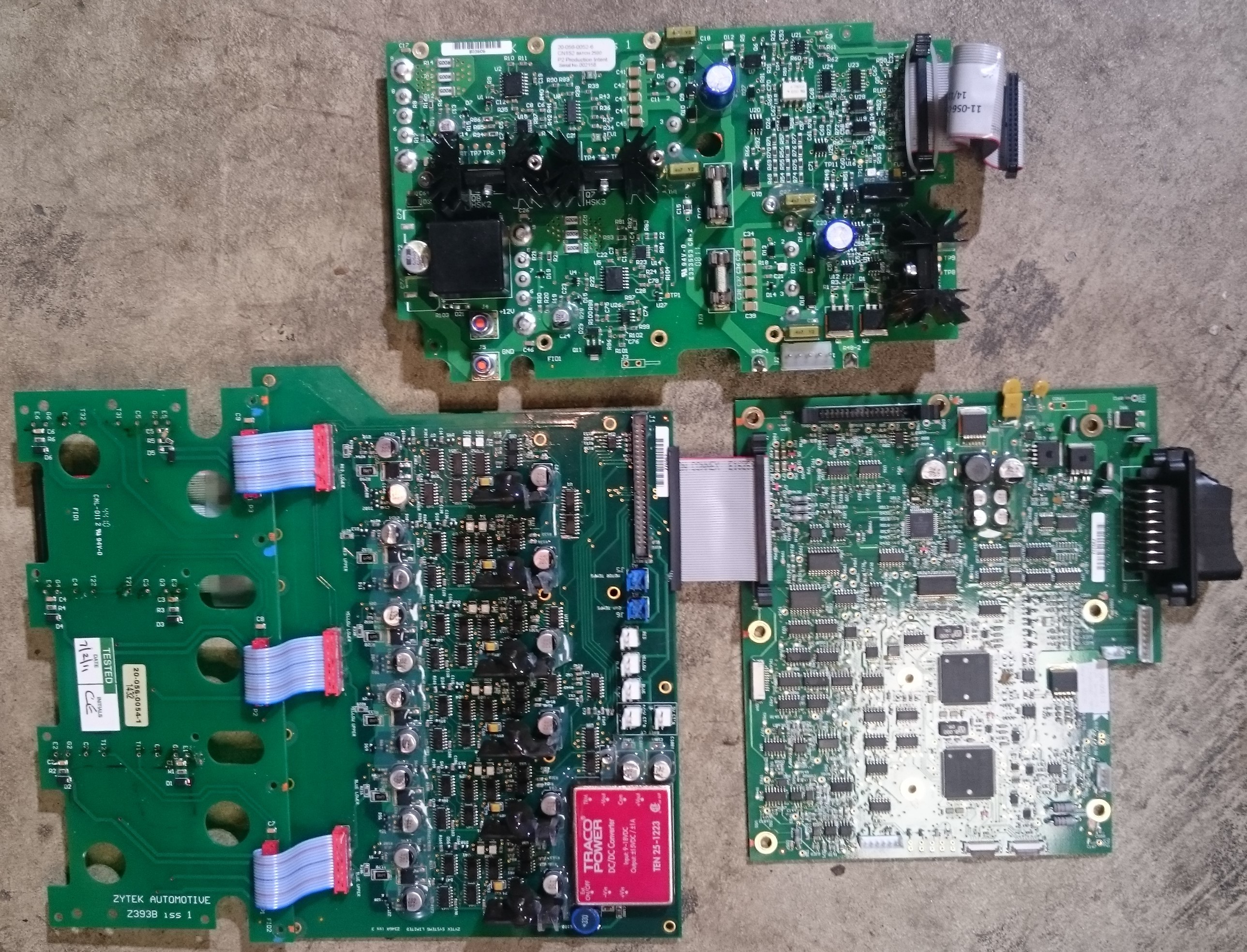
    The circuits are split between 4 PCBs:

    Top is the 400V-12V DC/DC board (heatsunk power modules are below the PCB) left is the board that mounts on the IGBT module, connected to it is the gate drive board which has 6 identical driver circuits, each one with an isolated +15/-5V power supply and optocouplers for signalling. It also contains some logic to prevent both switches turning on at the same time (called shoot-through protection or deadtime as it also ensures a time where both switches are off) The current sensors also connect to this board, so it has a +/- 15V power supply to power these.

    Lastly, the control board is on the right. it contains a PIC microcontroller I assume for monitoring circuit operation and two big Infineon microcontrollers, these clearly generate the motor control signals. They connect to the dual CAN bus and run in parallel for redundancy. A bunch of logic on the left of the board stitches the signals together...

    Read more »

View all 2 project logs

Enjoy this project?

Share

Discussions

Adam Curtis wrote 11/13/2020 at 17:50 point

Hi Jarrod,

Any thoughts on this over the past couple years? Would love to hear if any updates. 

  Are you sure? yes | no

sevenata wrote 11/14/2018 at 09:26 point

Hi Jarrod, do you have part numbers of the engine and the gearbox? Thx

  Are you sure? yes | no

leonrod wrote 04/12/2017 at 14:18 point

Hi Jarrod, This is great stuff. Is it possible for you to share some of the motor dimensions?

  Are you sure? yes | no

Jarrod wrote 04/12/2017 at 20:52 point

Dimensions for the motor+gearbox? I do have a rough 3d model of just the motor from when I was considering making an adapter for the mitsubishi gearbox. Here are the dimensions from the zytek website.


Obviously this doesn't include the Daimler gerabox

  Are you sure? yes | no

Element Green wrote 11/05/2016 at 04:11 point

Came across this while seeking affordable integrated electric drives for EV conversions.  I'd really like to see a solution for multiple motors for AWD and other scenarios, transaxles like this are getting pretty close.  Thank you for your efforts!

  Are you sure? yes | no

jlseemu1 wrote 09/30/2016 at 06:35 point

This is awesome; I've been waiting for someone with some solid EE skills to tackle this... the package is so cheap for the components you get.

 Out of curiosity, have you considered trying to spoof the CAN bus signals of a properly operating SMART car to get the existing logic boards to work?

  Are you sure? yes | no

Jarrod wrote 09/30/2016 at 07:57 point

That would be the easiest and probably safest way, alas I don't have access to a working car to sniff the CAN packets. There is a group in Illinois working on this approach. I'm getting in contact with them and will see, maybe developing a CAN control box will be the way to go. In the mean time, I'm gonna do what I can with my current approach.

  Are you sure? yes | no

Similar Projects

Does this project spark your interest?

Become a member to follow this project and never miss any updates