nerd.king
-
Major Milestone
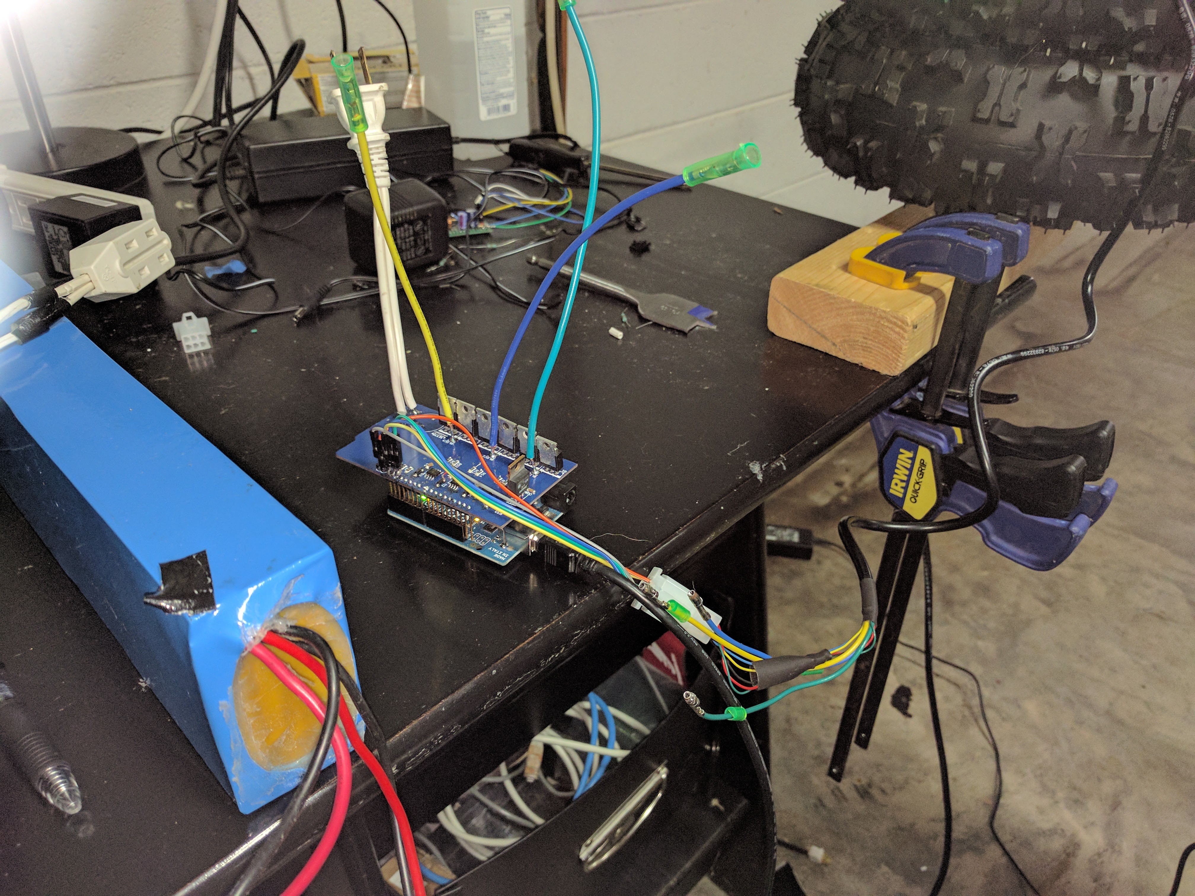
06/12/2017 at 00:30 • 0 commentsI have built up a couple of the new boards. I figured out a flaw with the voltage regulator circuit and swapped out that part.
This makes the whole board a lot more stable.
Using a power supply, I was able to get the hub motor spinning both in forward and reverse.
-
A lot has happened...
05/22/2017 at 12:17 • 0 commentsSo in the 2+ years since the last update a lot has happened.
My family expanded by additional boy this year and I am 2 years into my Master's of CS at Georgia Tech.
Children and school has drained almost all of my free time so OpenBLDC has been a tertiary goal. At the end of 2014 I purchased a hub motor off of alibaba and about a year later I purchased a second motor as well as two batteries and a battery charger. This motor will be a fundamental building block of OpenRover.
With the impending arrival of boy #2 this spring(2017), I took a semester off of school. The goal was to get the hub motors spinning so that I could submit an elective to build OpenRover over the summer. I was able to get two off the shelf motor controllers eval kits(Monolithic Power Systems EV6532). I spent January and February attempting to get the eval boards working with Hub motor. I hit one roadblock after another and was only able to get the wheels to move an inch before the controller would fault out. There was an ridiculous amount of noise on the circuit feeding back from the motor. I build isolation circuits and separate power regulators but gave up on these controllers.
My second attempt at off the shelf motor controllers were scooter controllers off of Alibaba. These were pretty low cost and I was able to get them in two weeks. I ordered three controllers so I could take one apart and evaluate the design. When I got the controllers they had about 7 pig tails on them, I could figured out power, motor and hall connectors but the company would not give me any documentation on the controllers.
So I took one of them apart and I was astounded my how simple the controller is. This design gave me some ideas on how to relayout my shield to handle the higher current(I pop traces on the original shield). Up late at night with my newborn, I was able to layout the new shield and submit them to dirtypcbs.
I have built one of the new shields and I hope to test it in the coming days. Additional Georgia Tech approve my elective and I was be building and modeling my rover over the summer with a Professor from France :) My hope is that I would be able to turn this project into a Master's thesis. I think I would be the first online student to do this.
![]()
-
New motor
12/08/2014 at 19:26 • 0 comments![]()
This is a hub motor I found on Alibaba and finally got it in just recently. I build a test fixture for it and I just need to wire up the connector. It is 36V 250 Watts but is supposed to have a low free spinning current. It came with hall effect sensors so I am going to trying to get it working with them first and then might go back and work on the back-emf routine. It was fairly cheap but shipping was killer for just one sample. Hopefully get the cost down with higher volume.
-
Update
10/08/2014 at 16:18 • 1 commentThanks for the post on Hackaday and I promise that I have not abandoned the project. Been a little distracted recently,
![]()
I promise that is a Hackaday shirt that I got from the Hackaday prize. I have made a really basic current limiting circuit but have not tried it out yet. I hope to get to it once things settle down shortly.
-
Motor spinning
08/21/2014 at 19:58 • 3 commentsSo I hooked the new motor up the controller and ran it with a 10 ms and 1 ms delays. Since there are 6 commutation states, I think this correlates to 1000 and 10000 rpm respectively. If any load is applied, the motor will stop spinning because the states are blinding running. One issue came up, the motor is rated 24V @ 30 watts but it is pulling 6.5 amps. I also noticed that the 24V rail was sagging to 12-19V. With this much current, the motor was getting very warm so I didn't run it very long.
Here is a video of the new motor running at the above speeds.
-
Latest Updates and Architecture diagram
08/19/2014 at 00:22 • 1 commentSo I waited a week to get the new motor only to find out that the old one had toasted some of the FETs and some really odd behavior was occurring. I decided to build a new shield up from scratch but I had to order some additional FETs.
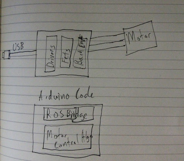
So today I got the current board to run through all commutation stages with the LED test fixture.
Here is the horribly simple architecture diagram. The pic makes the assumption that the Arduino io will drive the FET drivers. Hopefully this week I can get the new motor hooked up and running.
![]()
-
Motor spinning kind of
07/25/2014 at 00:29 • 0 commentsSo I hooked the 3 phase motor I have up to the controller today. It spins then the power supply over current protection kicks in and the motors stops this process continues. I need to find a larger current power supply to see if Open loop control work. Here is some video
-
Christmas Lights
07/23/2014 at 23:53 • 0 commentsProgess is being made. I kind of dead bugged a LM317T onto the side of the shield. It creates a regulated 13V rail that will power all of the drivers. I also switched out all of the drivers for new chips that I had just got from digikey. At first 4 of the 6 commutation stages were working, but then I discovered one of the resistors was not soldered to the board and that solved the issue. Currently I am cycling through the 6 commutation stages with 100 millisecond delay between each stage. Here is a short video.
-
Continuing adventures
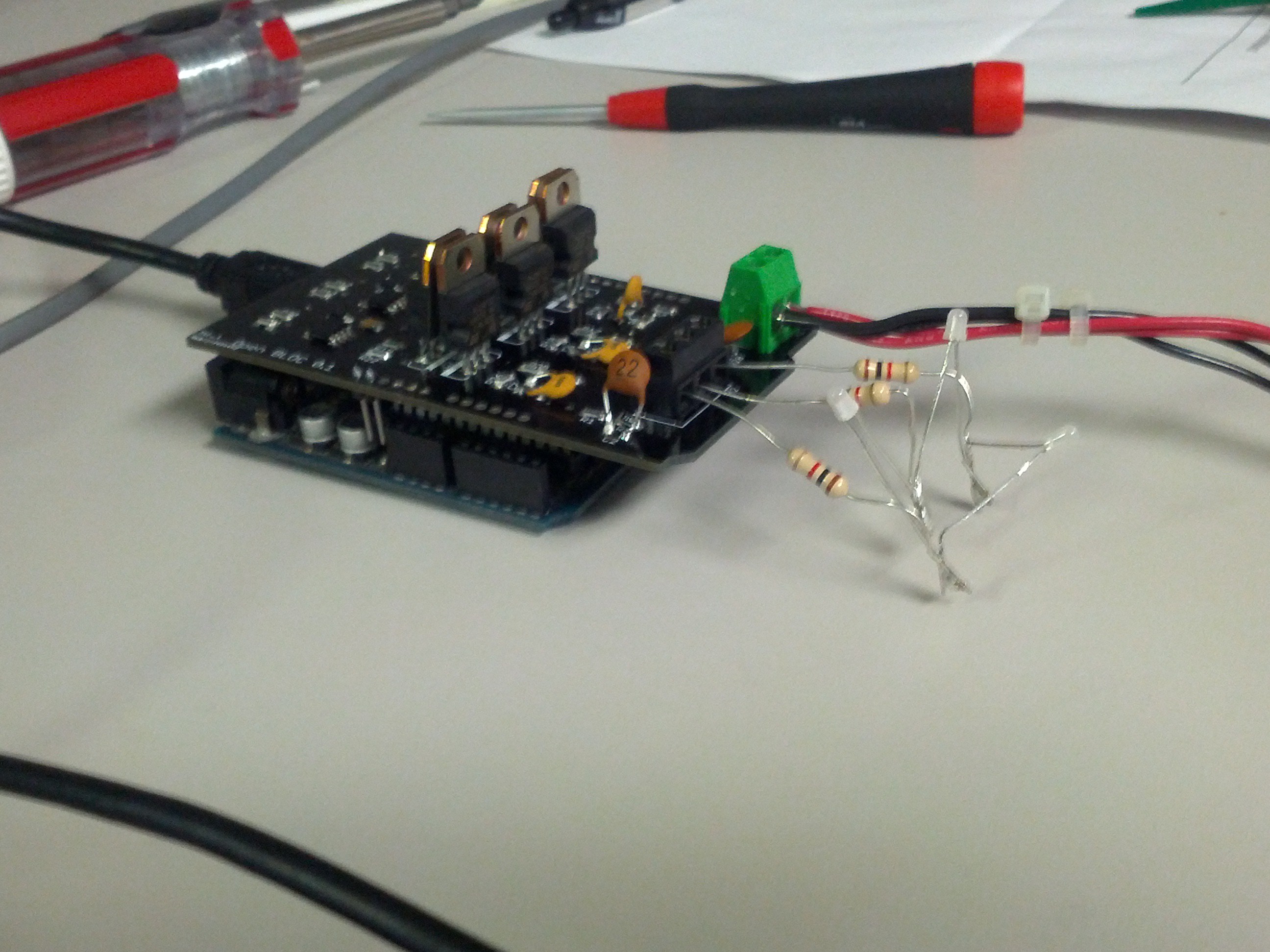
07/17/2014 at 16:42 • 0 commentsSo I continue to troubleshoot the PCB. I hooked up the motor with a variable power supply and got to see the motor jitter a little bit but it caused the power supply to over current and something is just not right with the commutation stages. One of my coworkers suggested that I make a motor situlation with 3 resistors and 3 bi-color LEDS. So I hooked this up and I got 1 green, 1 red and a very weak red on the third one. The drivers seems to be getting too hot or something and shutdown after a while of running so maybe having direct access to the power supply is dangerous for these ICs. I am going to look into maybe putting a 15V regulator in between them and the 24V rail. The need 10-25volts to run but I am unsure about how much current they will try to pull especially when driving the fets.
![]()
-
4th of July Fireworks
07/07/2014 at 13:35 • 1 commentSo I hauled a bunch of my stuff to my parents for the holiday, much to my wife's dismay. My goal was to see if I could get the motor spinning open loop control. I brought a wall wart that output 14V@0.5A and I used three 1k resistors as the load. I cycled through the commutation phases and could see some voltage on each resistor. I changed the delay to 1 sec from 100msec and I could see 14V jumping from phase to phase. I changed the wall wart for the massive 24v@20A supply and I verified that the 24V was moving correctly.
I changed the timing back to 100msec and attached the motor. The motor did not move so I measured the voltage between two of the leads. As I did this one of the drivers popped, thus ending my testing. I really wish I had a scope to verify the faster timing voltages. I might try to see if I can use one at work, after I swap out the toasted chip. I am at a bit of a loss by the driver fried, I wouldn't think that the gate of the FET is pulling very much current. I am also wondering if there is a problem with the motor. I got it for free and I am thinking of purchasing a small motor just to test and develop the code. One of the secondary goals is to create a motor profile that can be loaded based on the type of motor being used.