Close
0%
0%

reCLOCK

retro LED clock

Similar projects worth following

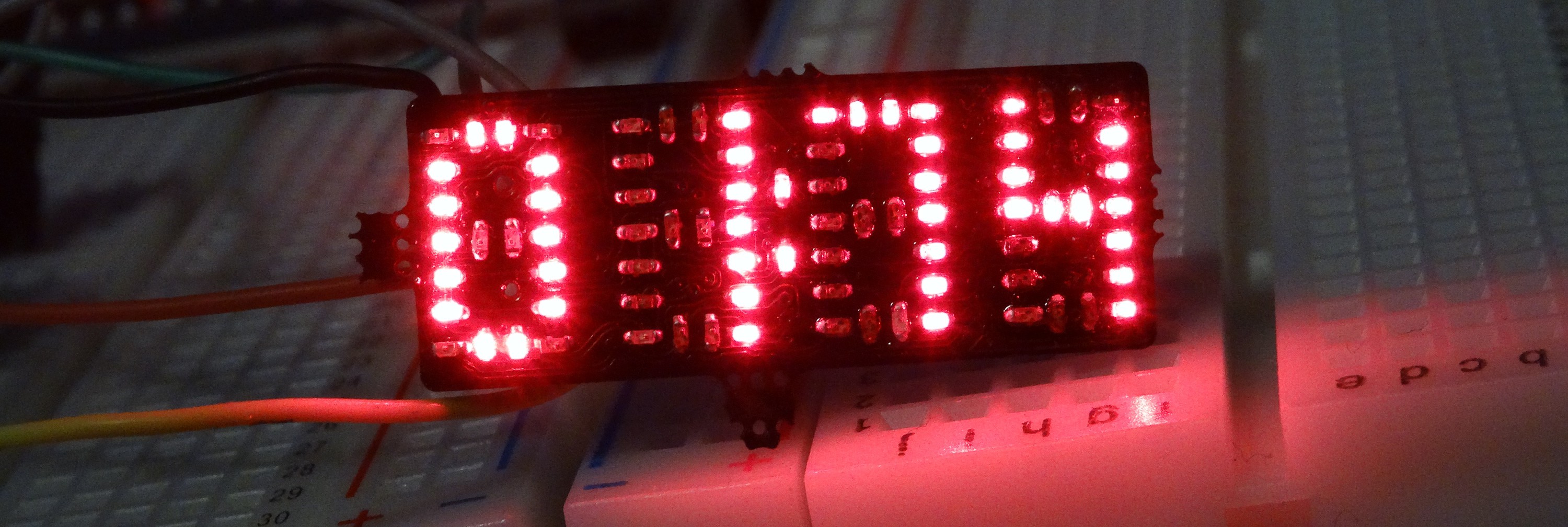
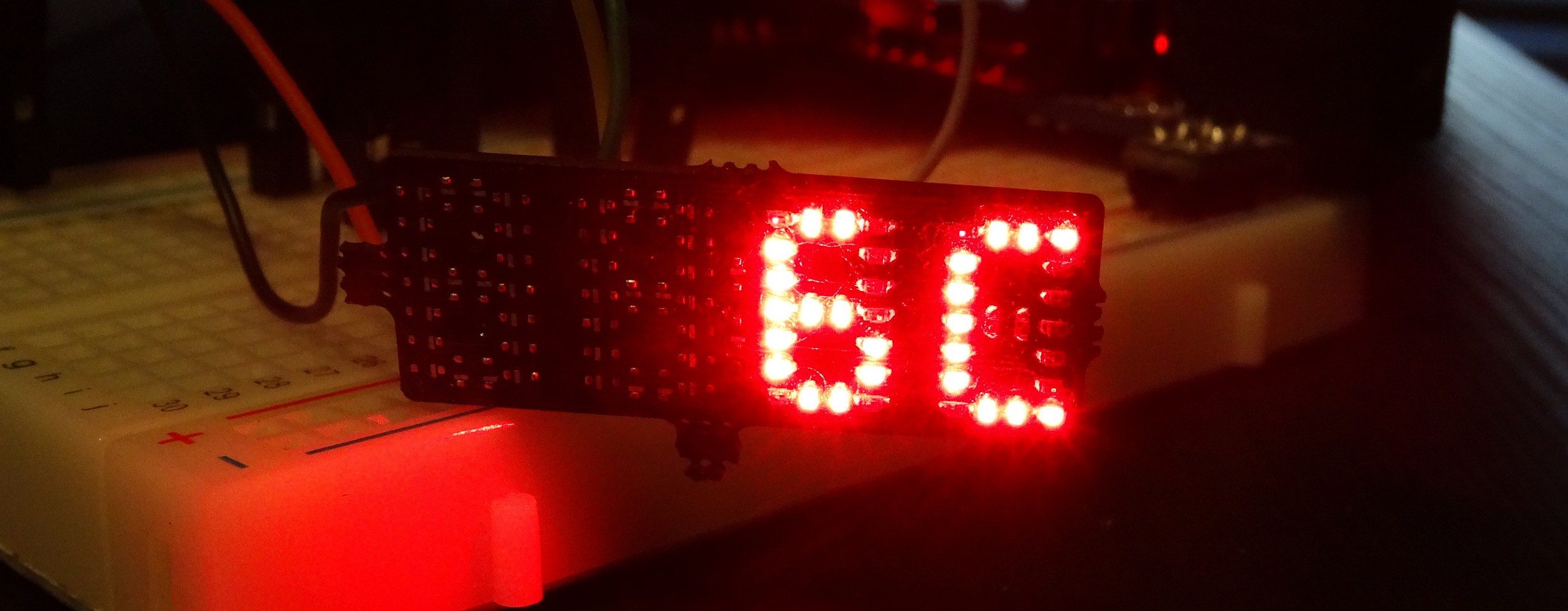
While working on #reDOT and #PICTIL I had the Idea of a single PCB LED-Clock. So I came up with reClock. Looking at the LEDs you can see four digits arranged lie in the TIL355-style also used in the #PICTIL project.

Overview

  • four digit TIL311-style LED display with dots for a clock
  • USB connector on the Back (as power connector an for synchronisation / programing)
  • controlled by modern ARM Cortex M0+ Microcontroller (Atmel SAMD09 (no USB) or SAMD11 (USB) )
  • RTC integrated into Microcontroller
  • LEDs controlled with 16-Bit constant current sink shift Register (columns) and seven high side drivers for the rows.

Intended as small clock on display frames, controlled and powered from PC. Clock gets synchronised to PC clock trough some software during starting up the PC and runs than on by using the Microcontroller's integrated real time clock.

More details coming probably soon....

Hardware - System

A block diagram does say more than words... (even when it is hand drawn/written)

Software

Till now only an early test firmware is available. I will push the software from time to time to Github (see link on the right)

Credits:

This was hugely inspired by:

#DYPLED by @Yann Guidon / YGDES and

#4 digit charlieplexed segment display by @bobricius

Notes/Ideas for next revision / Errata

  • The p-fet circuit is not working if V_USB>3,3V Fix: Power everything with 3.3V
  • Use more clearance around testpads and use bigger ones
  • Use lowside drive in QFN package
  • Update P-Fet Type (DFN style ones like TI's nano-Fets)
  • Include some battery backup circuit. (min two diodes for simple battery backup on VCC of MCU and increase normal suppy to 3.6V) Use free GPIO for VCC sense

  • 82 × LED 0402 any color
  • 1 × SAMD09/11 ARM Cortex M0+ Microcontroller (SAMD11 with USB)
  • 1 × MBI5026 or MAX6971 or SCT2024CSSG 16-Bit constant current sink shift register with serial control interface
  • 1 × LP5907UVE-3.3 3.3 V LDO in super tiny BGA package
  • 1 × mini USB connector

View all 8 components

  • rev2 - now with more BGAs

    Alex05/08/2017 at 21:08 0 comments

    Also the first PCB, did worked. There are some issue:

    • It could only run on 3.3V because of a mistake with the p-fets
    • The footprint of the LEDS were so much undersized, that soldering was quite difficult an unreliable
    • The TSSOP package of the shift register looks to big

    As Solution a made a new revision:

    • Now with smart integrated high-side switches (TPS22912 or similar) and because of these with more BGA parts
    • Bigger Solder pads for LEDs. Some new routing was needed, because now only one trace fits under each LED. But OSH-Park's new 10mil Drills helps a lot.
    • the shift register is now also QFN.

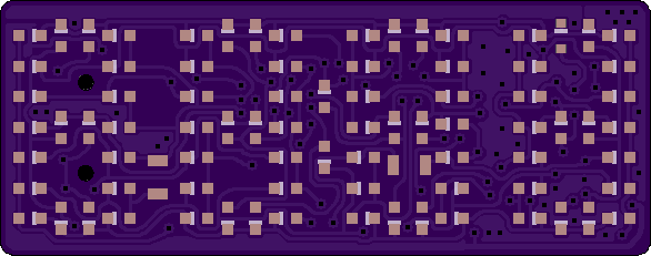
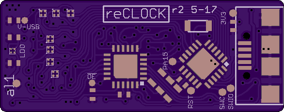
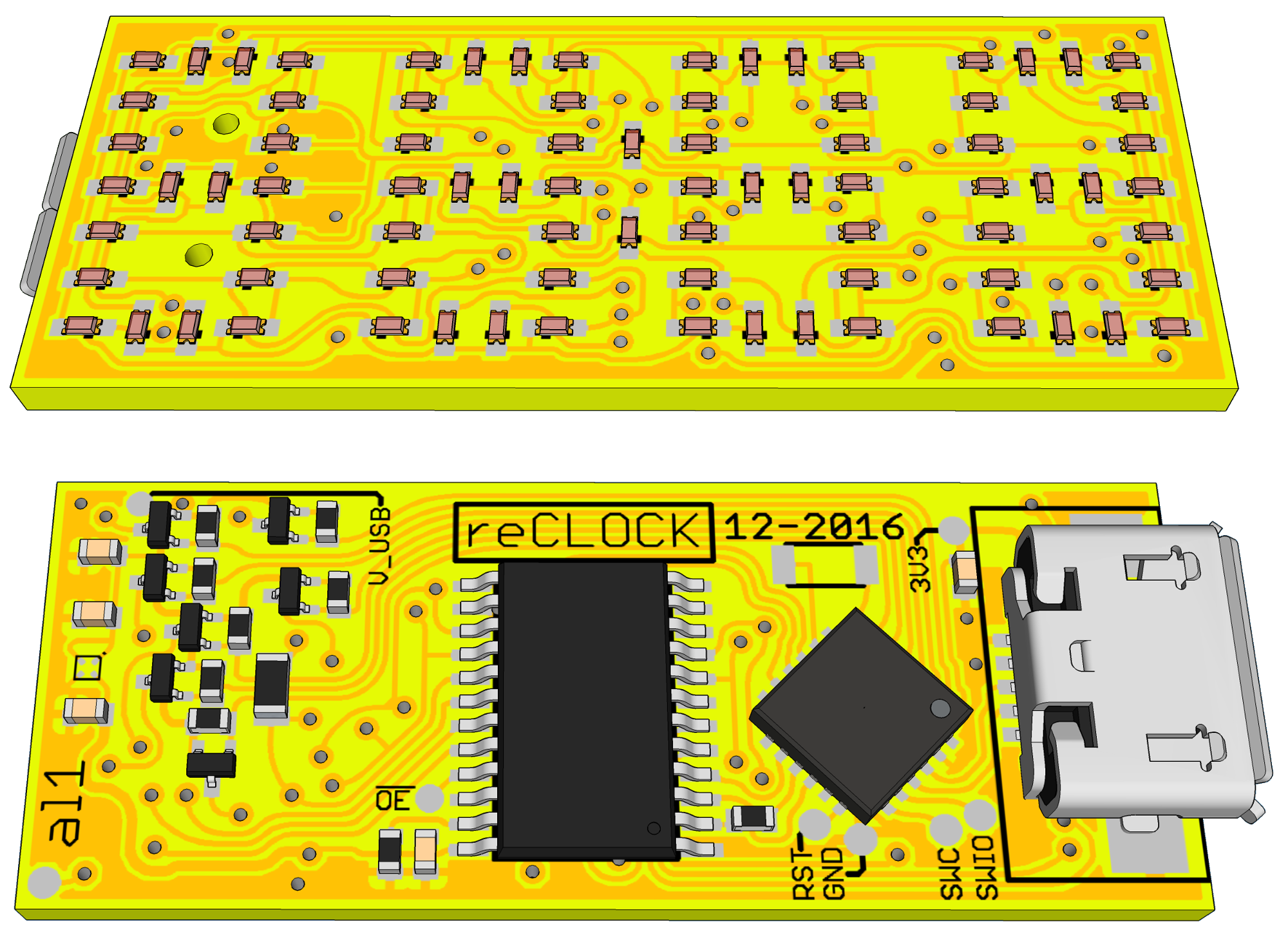
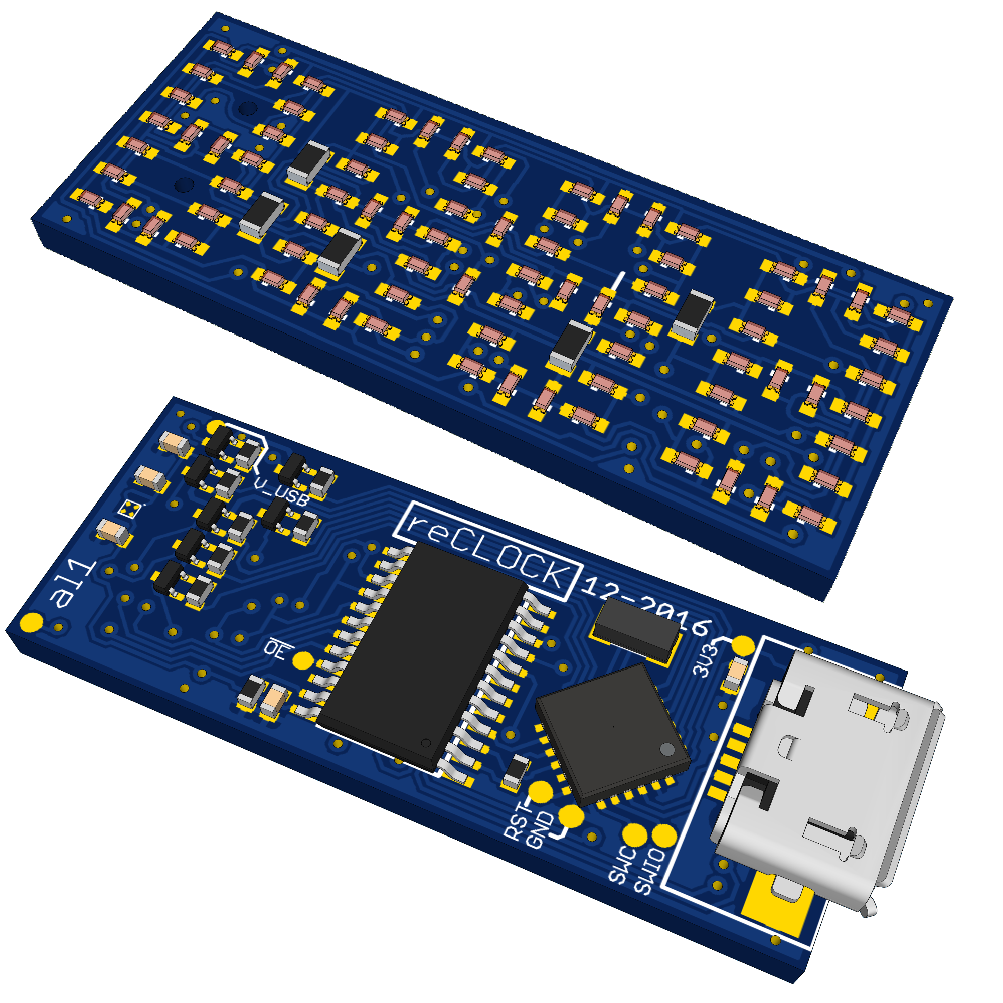
    Here some preview of the boards:

    https://644db4de3505c40a0444-327723bce298e3ff5813fb42baeefbaa.ssl.cf1.rackcdn.com/0a4dee0b8100185b6cf9e72fe5e1ab41.png

    https://644db4de3505c40a0444-327723bce298e3ff5813fb42baeefbaa.ssl.cf1.rackcdn.com/e75af9613ec6411b1cc002d919543d40.png

  • now with all for digits

    Alex03/31/2017 at 21:02 2 comments

    all soldering done

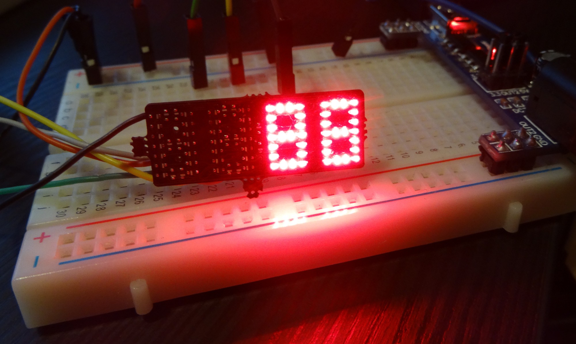
  • two digits soldered and working

    Alex03/29/2017 at 18:45 1 comment

    it is partial working!

  • update

    Alex03/29/2017 at 16:28 0 comments

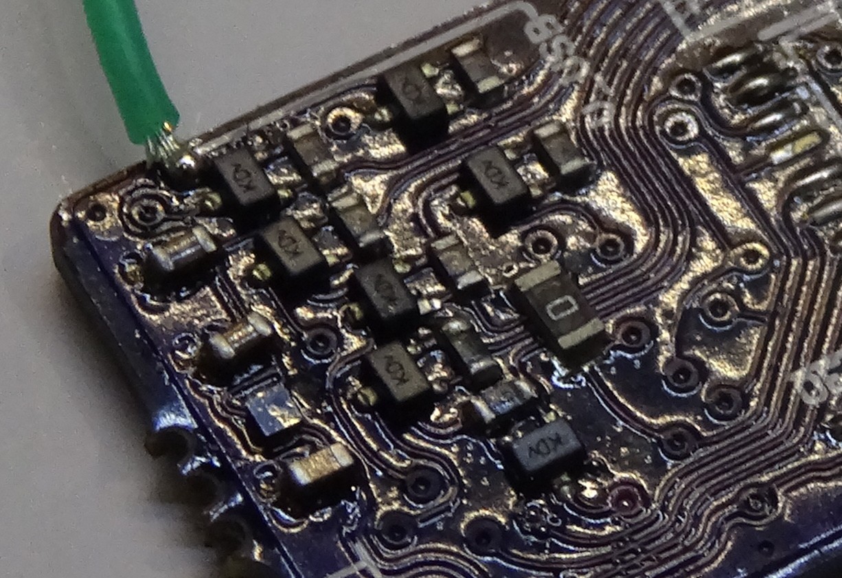
    This project is still ongoing and I did received the PCBs some time ago. I also started soldering and programming. Here a picture of the line driver section of the PCB:

    I also got a little bit into trouble with the LEDs. Some how I placed them all in the wrong direction in the schematic. So that the cathode marking on the PCB is now an Anode marking. The really bad thing is that I noticed that after soldering all LEDs the wrong way around.

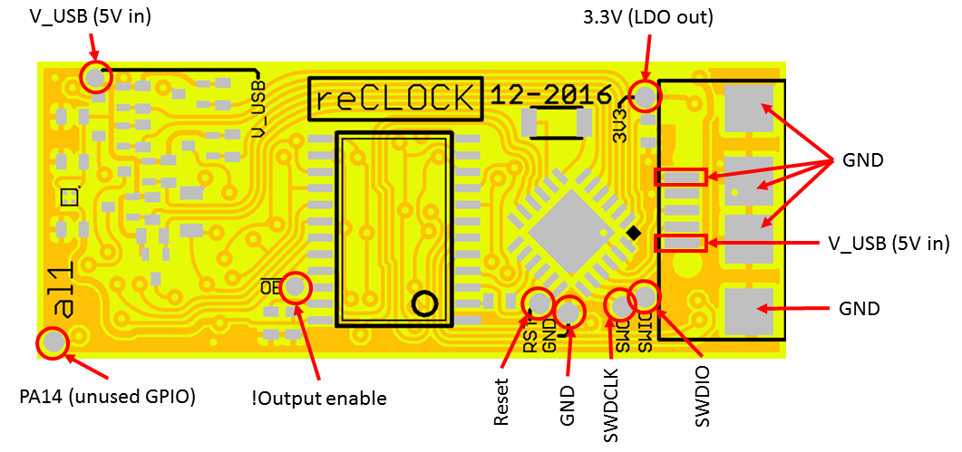
    During the first programming/debugging secessions I also made this test pad overview:

  • PCBs rev1

    Alex01/12/2017 at 18:01 0 comments

    The PCB design is ready. And there are now only LEDs on the front side. And no more 0 ohm SMD resistors as bridges.

  • _dump for old details and images

    Alex01/12/2017 at 16:56 0 comments

    ....


    first published renders. (with ugly resistor bridges on the top/front layer)


View all 6 project logs

Enjoy this project?

Share

Discussions

davedarko wrote 05/09/2017 at 09:47 point

some green leds on a flexible board, embedded in your arm would make a nice cosplay gadget ;) what was the name of that Justin Timberlake movie? :D great stuff!

  Are you sure? yes | no

Elliot Williams wrote 05/09/2017 at 09:37 point

It's even smaller in real life!  (At least if you view this page on a 21" monitor.)

  Are you sure? yes | no

K.C. Lee wrote 03/31/2017 at 21:56 point

Round traces!  Fine soldering job!   I am too lazy - I bought a 4 digit 7 segment display from China.  (Hide in shame)

  Are you sure? yes | no

Alex wrote 03/31/2017 at 22:10 point

Thanks

  Are you sure? yes | no

chmod775 wrote 01/31/2017 at 23:40 point

Very cute and compact layout! I'm impressed.

Just a tip, try to avoid those 'non through hole reinforced' micro USB connectors. Even with a minimal force they snap out from the board.

  Are you sure? yes | no

Alex wrote 02/01/2017 at 16:32 point

Thank you.
Yes these USB connectors are not mechanical strong. But THT would not fit here and secured with a blob of hot glue or epoxy I made good experiences with these USB connectors. They are just perfect if the other side is populated an there is no place for holes.

  Are you sure? yes | no

Similar Projects

Does this project spark your interest?

Become a member to follow this project and never miss any updates