Close
0%
0%

8BitRobots Module

A common hardware, software and 3D printed module to enable fun, educational robots anyone can print and program.

Public Chat
Similar projects worth following
I started to build robots for fun at the end of 2015 when I built an underwater robot (https://hackaday.io/project/8343-borgcube-rov). In the last few years I've built a few more, including a car, another ROV, a rabbit, a rolling ball, and a robot arm. Some of these have used custom hardware, some just assembled Adafruit and Sparkfun boards, some Raspberry Pies(?!), and some Beaglebones. Through this process I've built and rebuilt the software to control these things until I have a common, Javascript platform running on everything. In parallel I've refined what hardware the robot use until I have a common hardware platform with all the essentials they share. Together this makes the 8BitRobots module.

The 8BitRobots module consists of the following 6 components:

  1. Hardware
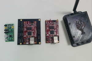
    The Pi Zero is the ideal base for a robot. It's cheap, relatively powerful, runs Linux and comes with WiFi and Bluetooth. Add to it the RoBonnet, my Pi Bonnet which includes PWM outputs (servos and ESCs), an H-bridge (motors), TTL serial (expansion), I2C output (more expansion), encoder inputs (RPM), pressure/temperature sensor (altitude), IMU (orientation), power monitor (battery management), and DC power regulator (lots of different battery options). The result is everything needed for a bunch of different robots.
  2. Software
    To manage everything, there's a Javascript, distributed robot platform running on the Pi. A robot can be made one or many Pis. This software binds them together into a single, simple, robot API (https://gitlab.com/8BitRobots).
  3. Programming
    You can write your robot in Javascript, but it's easier to write it in Blockly. Blockly (from Google) is a Scratch like graphical programming language. Here it's been adapted to create robots. It runs in a web browser and makes it easy to turn a bunch of hardware into something much more useful.
  4. Controls
    If you've every played with one of those cool Sphero toys, you'll know how good it is to use your mobile phone to control a robot. The same interface ideas are used here, but with a few more tricks to make it configurable for your particular robot's needs.
  5. Installation
    If you just want the software to create a robot without learning all about Linux, then everything for an 8BitRobots node is rolled into a custom Linux distribution. Download it onto an SD card, boot, and you're ready to go.
  6. 3D Printing
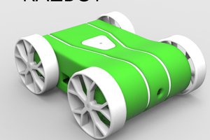
    Finally, what's the point of building robot hardware then having nothing to use it with? So there's also a bunch of 3D print-at-home robot projects. Print a few 3d parts at home, combine it with the components above, and build something fun.

RoBonnet_v1_0.brd

brd - 146.18 kB - 06/02/2018 at 20:28

Download

RoBonnet_v1_0.sch

sch - 371.97 kB - 06/02/2018 at 20:28

Download

Wheel.stl

Standard Tesselated Geometry - 3.29 MB - 05/23/2018 at 23:47

Download

Midframe.stl

Standard Tesselated Geometry - 279.38 kB - 05/23/2018 at 23:47

Download

Battery Holder.stl

Standard Tesselated Geometry - 148.91 kB - 05/23/2018 at 23:47

Download

View all 7 files

View all 6 components

  • Alternate IMU data filtering

    Tim Wilkinson11/21/2018 at 21:10 1 comment

    Continuing to tinker with my IMU fusion code. I'm currently playing with improving the data cleaning before the calibration process. In the ideal world (where calibration isn't necessary) the vector length of each point would be equal. Obviously that's not the case (and it part of what calibration is trying to achieve), but eliminating vector lengths with extremely small or large values seems like a good approach to removing outliers.

    _filterPoints: function(points)
    {
      const sqlengths = points.map((point) => {
        return point[0] * point[0] + point[1] * point[1] + point[2] * point[2];
      });
      const mean = MATH.mean(sqlengths);
      const std = MATH.std(sqlengths);
      const low = mean - std;
      const high = mean + std;
      const fpoints = points.filter((point, idx) => {
        return sqlengths[idx] > low && sqlengths[idx] < high;
      });
      return fpoints;
    }

    The above code does just this and, in some limited testing so far, seems to produce a more accurate and stable quaternion result.

  • Good software IMU with data fusion

    Tim Wilkinson11/20/2018 at 05:48 2 comments

    One of the single most expensive components on the Module board is the BNO055 IMU. In single quantities it costs $12 (https://www.digikey.com/product-detail/en/bosch-sensortec/BNO055/828-1058-1-ND/6136309). I, like many others, chose this chip because it has two very appealing qualities - it self calibrates and outputs quaternions. This avoids lots and lots of math on the host CPU; math I mostly don't understand.

    However, as I look at moving this module board towards production, the cost of this chip annoys me; especially when I'm designing various projects which don't immediately need an IMU. It increases the BOM costs substantially, while offering little immediate gain.

    Because I do want an IMU on this board, I've begun to look at alternatives. In that process I realized the only way to decrease the cost is to do the math on the PI.

    There are three sets of math that must be done for a good software fusion IMU:

    • Calibration - which turns the raw noisy sensor data into something more repeatable.
    • Cleaning - to eliminate poor sensor readings
    • Operation - turning sensors readings into usable rotations/quaternions

    Calibration Math

    I've taken a stab at IMU calibration math a couple of times before and ended up abandoning the efforts as the results were not good. There are lots of algorithms which attempt this process, and many of them appear to assume IMUs are far better behaved than they actually are. I eventually found this calibration explanation (https://thecavepearlproject.org/2015/05/22/calibrating-any-compass-or-accelerometer-for-arduino/) by the Cave Pearl Project which uses this tool (http://sailboatinstruments.blogspot.com/2011/09/improved-magnetometer-calibration-part.html) by Sailboat Instruments. Essentially a set of raw datapoint are gather from the magnetometer and accelerometer (each set form an elliptical shape) and maps them into a sphere centered on an origin. The  Sailboat tool (Magneto - https://sites.google.com/site/sailboatinstruments1/home) generates this as a vector translation and matrix transformation.

    While the Cage Pearl article discusses doing this analysis offline (they're using Arduinos which are not up to the online math), they include a C implementation of their algorithm; one quite capable of running on a Pi.

    Calibration Cleaning

    Just feeding a large set of values to the calibration algorithm will not necessarily get the best results. Ideally you need many points from all orientation of the IMU in order to get the best transformation. Also, because IMUs are noisy devices, they generate outlier values which can confuse the calibration algorithm.

    So it is necessary to clean the calibration data before using it to calibrate. To gather a "good" set of points, each point is translated from (x,y,z) form into spherical coordinates (inclination, azimuth); think of this as the longitude and latitude of the point on the surface of a sphere. We divide the surface of the sphere up into a number of "buckets" of approximately equal area, and place each point into the appropriate bucket. The goal for good calibration is to sample enough points and place a minimal number into each bucket.

    One the buckets are full, we must eliminate any outliers before passing the points for calibration. Outliers are consider to be any point where an (x,y,z) value is outside 2 standard deviations of the mean. Once removed from out dataset, the resulting points generate excellent calibration data.

    Operation Math

    Using the calibration data, we can now adjust the IMU's raw values to make them usable. However, we still need to turn this data into a quaternion. A quaternion is a 4-dimensional vector which is used here to represent the rotation of an object (https://en.wikipedia.org/wiki/Quaternions_and_spatial_rotation).

    The best algorithm I found to handle this process is by Sebastian Madgwick (http://x-io.co.uk/open-source-imu-and-ahrs-algorithms/). It takes (x,y,z) inputs from the three IMU sensors...

    Read more »

  • Network configuration

    Tim Wilkinson09/30/2018 at 23:48 0 comments

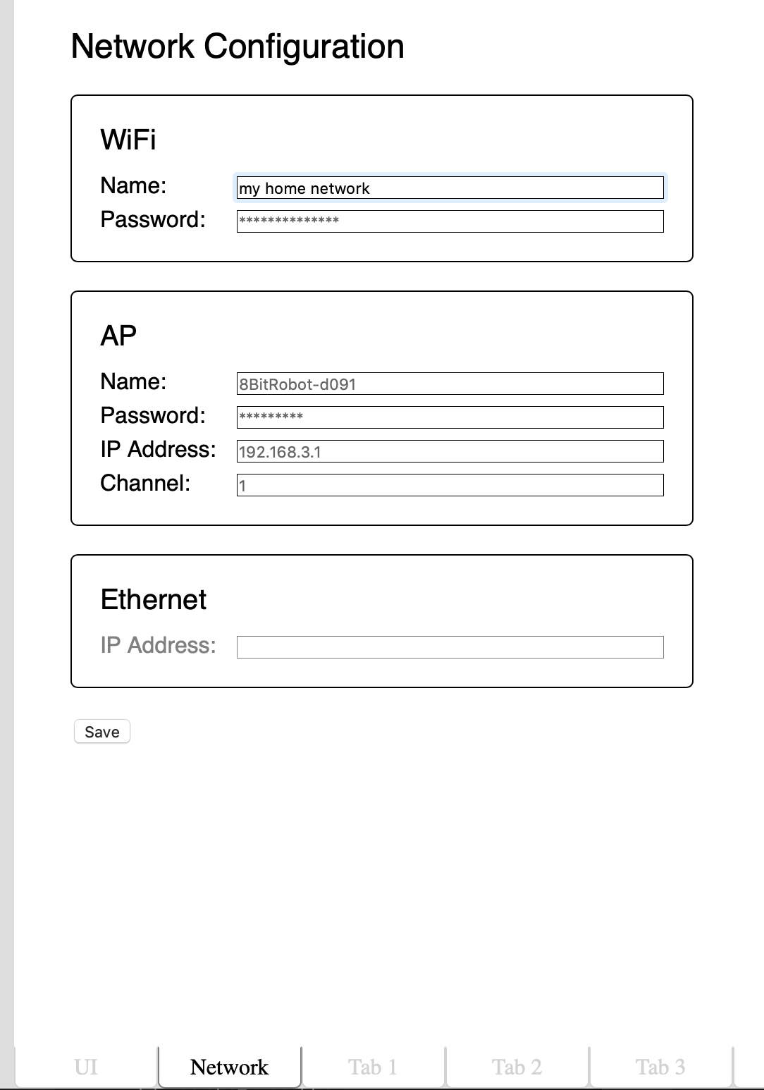
    Today, what is probably the last part of the development environment landed; the network configuration tab. Ignoring my excellent visual design skills as demonstrated above, the Network tab allows configuration of the three networks supported by the module:
    • WiFi - the wireless connection to a local wireless network (e.g. your home network)
    • AP - an access point network allowing you to connect directly to the module (for when you're not at home)
    • Ethernet - a wired network if the module detects a USB ethernet device has been connected.

    By default the AP network is the one you might use to first configure the board as the network name is visible to any WiFi scanner and the password is well known. From there you might reconfigure that network, or connect the module to your local network (which just makes everything a little easier for later development).

    The ethernet configuration defaults to serving addresses to whatever connects to it; ideal for just plugging directly into the ethernet port on a laptop. However, it the address is switched to DHCP it will instead act like any other client device on a shared network, soliciting an address from your local DHCP server.

  • UI Designer

    Tim Wilkinson09/23/2018 at 04:47 0 comments

    One of the original goals for this project was for robots built using the Module to be controlled by phone using a web browser. However, because each robot is unique, there is no one set of on-screen controls which are ideal for all robots. To address this we need a UI Designer; a tool for developer to drag-and-drop controls onto a virtual screen, and to include just the right controls in just the right places for each robot.

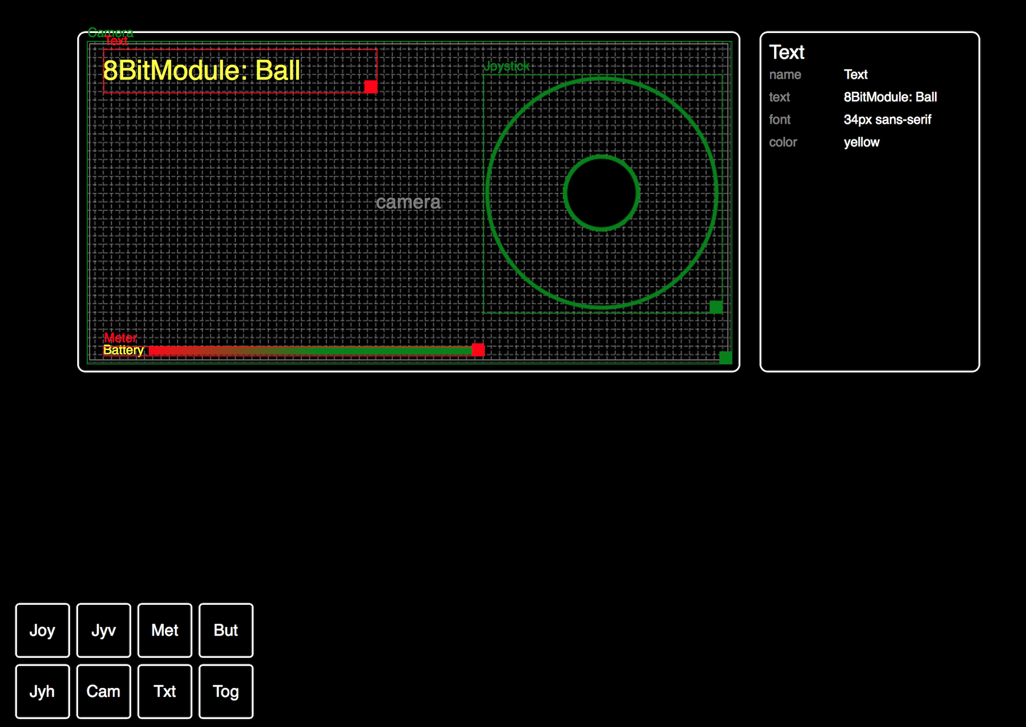
    The photo above shows V1 of the UI Design tool. This lives under the UI tab in the Blockly code editor which is already part of the Module's software stack. The Designer has three basic parts:

    • Virtual screen - the hatched space onto which tools can be arranged. Controls "snap" into place, which helps them move and scale depending on the size of the phone's screen.
    • Properties - the properties of the current selected control allowing customization
    • Controls - the periodic table-like set of controls which can be arranged on the screen.

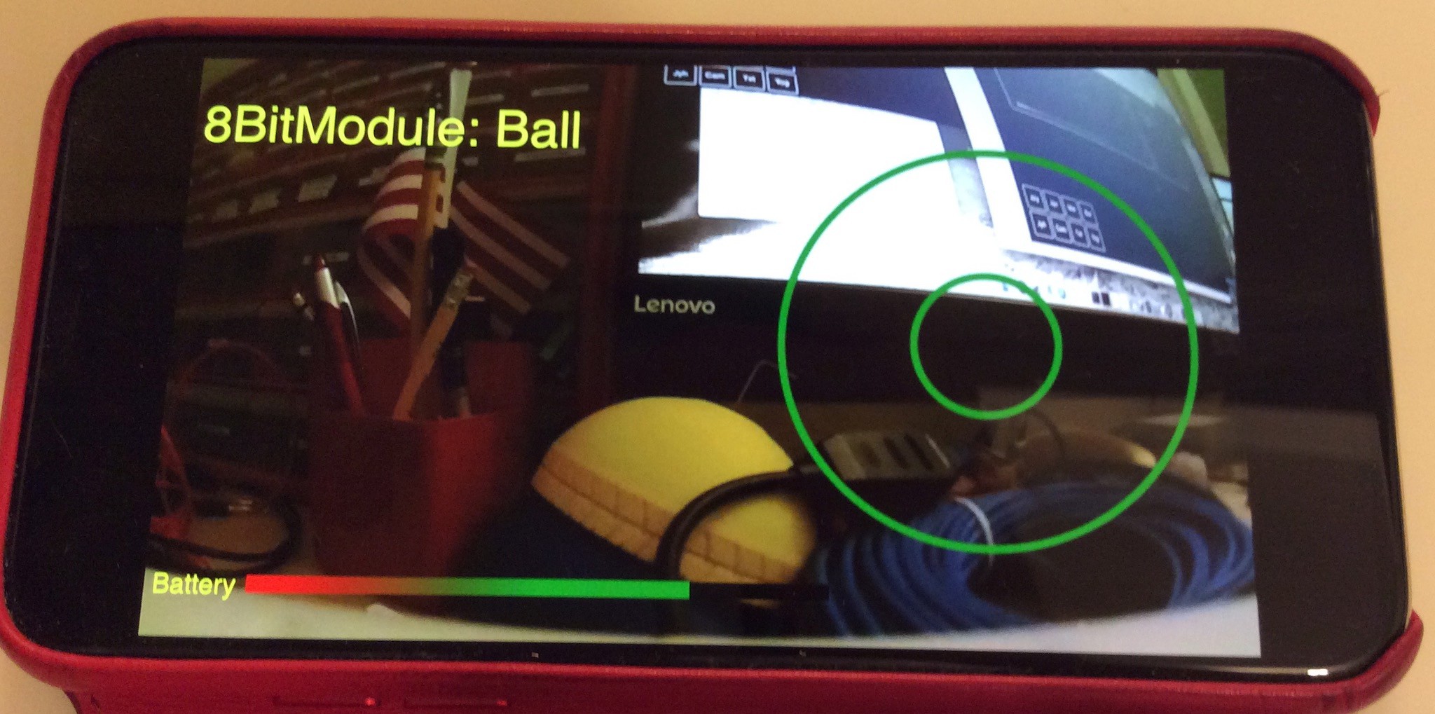
    The design pictures shows a fairly basic arrangement: a 2-axis joystick (on the right) for robot control, a title (top/left), a meter (bottom/left) displaying the battery health, and behind everything a camera feed from the robot. When displayed on the phone it looks like this:

    The controls themselves, once on screen, export their APIs by creating new Blocks in Blockly. Controls can either provide information (e.g. the current x,y location of the joystick), accept actions (e.g. setting the battery level) or both.

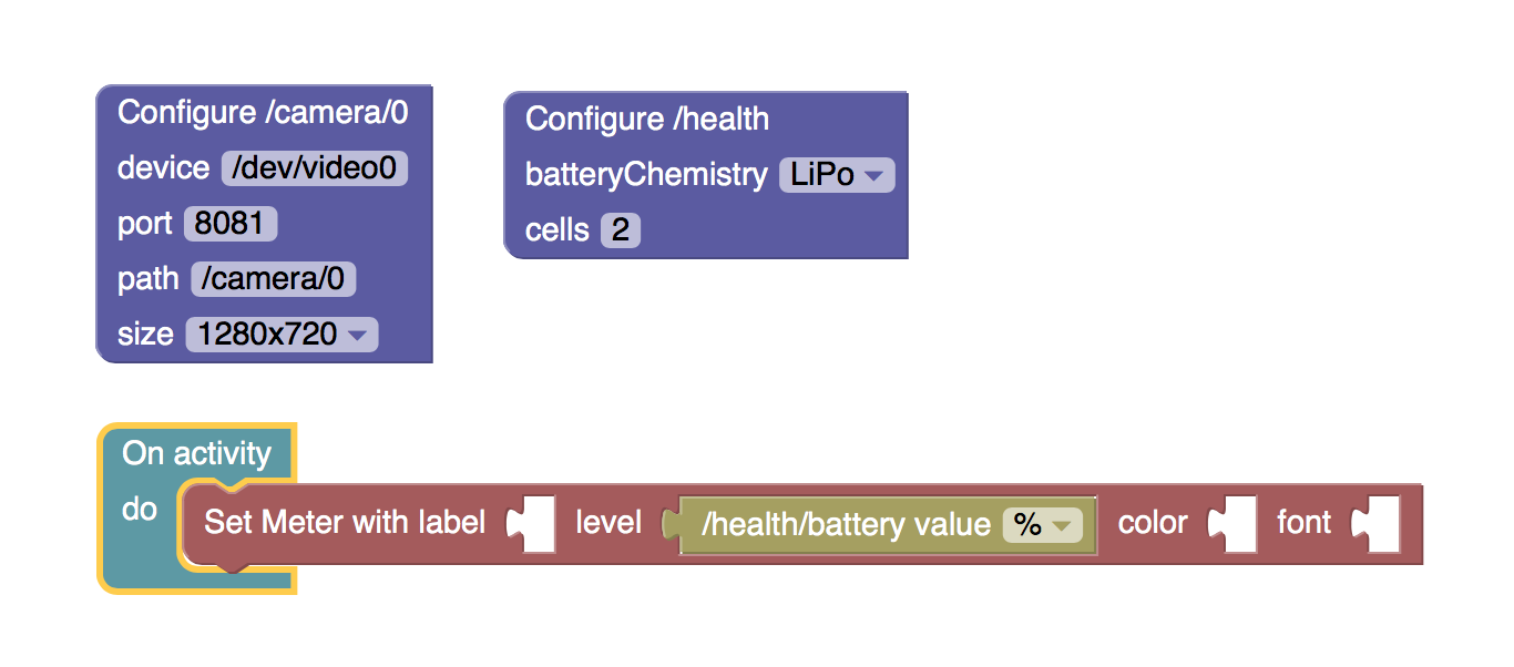
    Here is a snipped of the code to run the robot. Two blocks configure the camera and battery chemistry. The final block runs an activity which uses the current battery health (0-100%) and set the level of the meter in the UI (which you can see on the phone screen).

    Improvement

    This is the first version of the UI and there are obvious improvements:

    • Expand the controls available and make them more customizable.
    • Design more appealing controls! What I have here is pretty basic; it would be good to find some design help to make this all look more polished and professional.

  • Camera streaming @ 100ms, ethernet edition

    Tim Wilkinson09/15/2018 at 01:26 0 comments

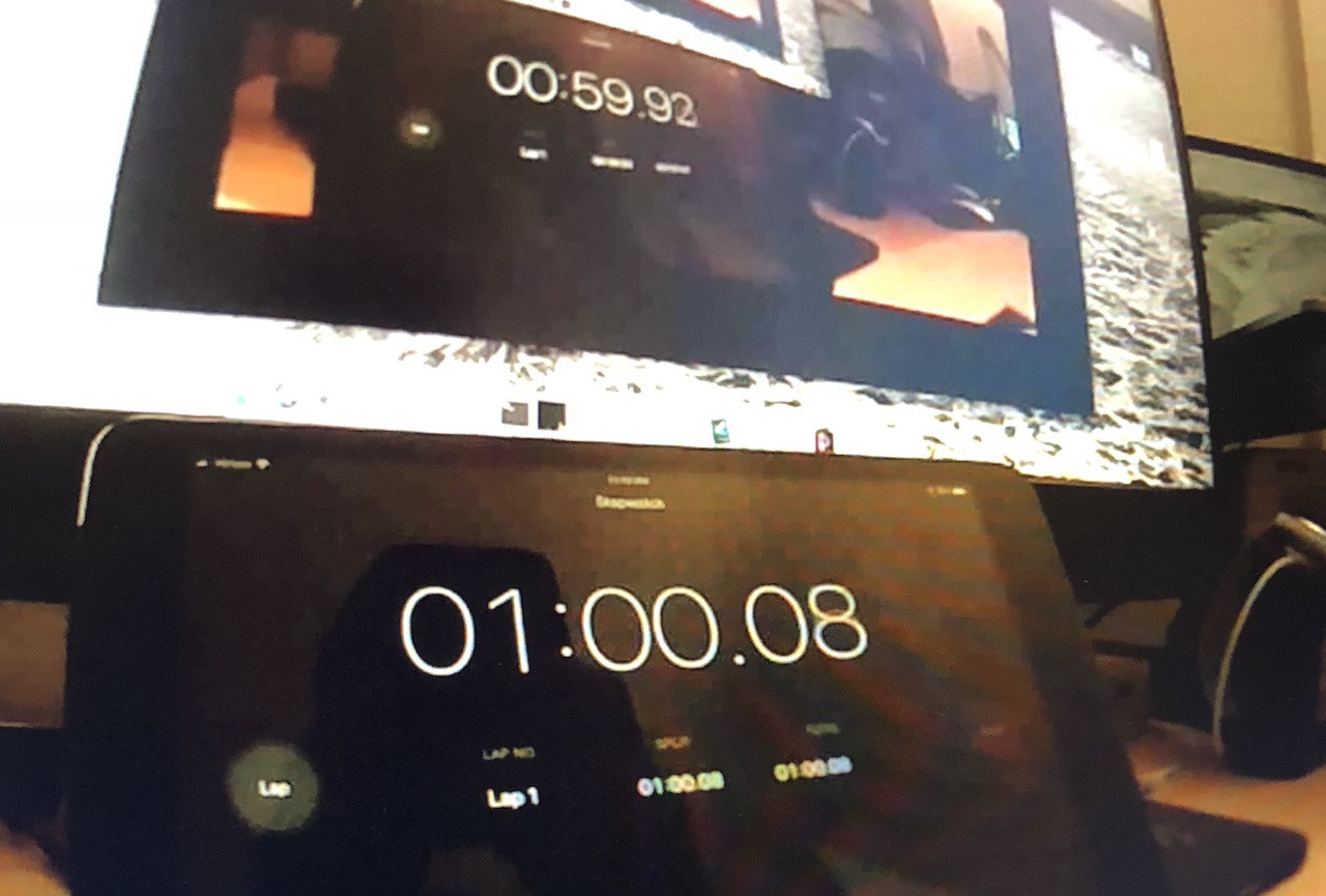
    The photo above shows the camera streaming over ethernet (the same software but part of the ROV build - see here https://hackaday.io/project/158799-sphere-rov-8bitrobots). While the latency over WiFi was ~160ms, here the latency is ~100ms which is a nice improvement if your robot happens to be connected with a wire.

  • Camera streaming at 160ms

    Tim Wilkinson09/11/2018 at 05:24 0 comments

    For some reason, streaming video from a Raspberry Pi camera across a network to a web browser is unnecessarily difficult.  You'd think it'd be easy enough to pop a URL into a video tag and all would be great. But obviously it's more complex than that. Once you've factored in video formats, container formats, streaming formats, and the matrix of these which your favorite browser might support, it all just seems a bit broken.

    Over the years I've tried many things to get this working, including wrapping mpeg4 video in streams only Chrome supports ... until it doesn't; or repurposing ffmeg to generate content which everything supports, but kills the cpu on the robot in the process. And it all kind of works until you start to notice that the video latency can just make it all unusable anyway. It's difficult to control an ROV when the video latency is a couple of seconds.

    So ultimately everyone falls back to the simplest thing - Motion JPEG. Motion JPEG is a sequence of JPEG images, formatted as a multipart HTML stream, which any browser with an IMG tag will display. One popular application for generating these streams is GStreamer, but GSteamer can do a lot more than just push JPEGs across a network, and for my purposes it's big, ugly and unnecessarily complicated.

    So, time to write my own.

    The new Camera app landed in 8BitModule GIT today and it's the simplest thing. On one end it reads JPEGs directly from the Raspberry Pi camera using the V4L2 interface, and on the other a super simple web server pushes these images across the network to whomever wants them. And that's all it does.

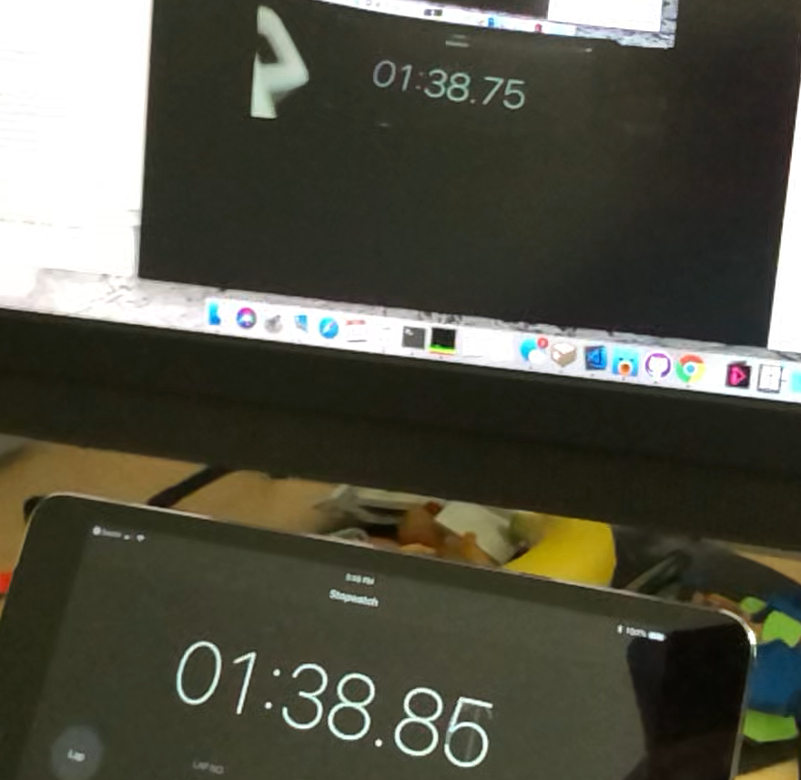
    One other reason to write my own Camera app is to manage cpu and latency. The first cut of the app had a latency of 1.5 seconds ... which was a bit depressing. But after lots of experimentation (and experience from my various other attempts), the app come pre-configured to deliver latency of about 160ms over WiFi (see the photo above - the top browser is displaying the video of the timer at the bottom). It does this in a few ways. First, the JPEGs are always 1280x720 which appears to be the optimal size. Second, it reads frames from the camera as fast as the camera provides them (which happens to be 30 fps). Finally, it send these images across the network at 60 fps regardless of the speed of the camera (the camera side and website run in different threads). The result is a stream with minimal latency and only consumes 18% of the Raspberry Pi Zero cpu.

    Why these values are the sweet spot I don't know. If anyone understand the latency of moving an image though a web browser and onto the screen I'd love to understand that. Delivering too few images to the browser seems to increase the latency, but why is that?. Is it possible to get more fps from the camera without a major hit on the cpu? Ultimately, where does that 160ms go? I'd love to know.

  • PIDs v2

    Tim Wilkinson09/03/2018 at 18:06 0 comments

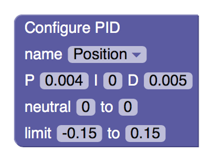
    While the original PID code worked well, I wanted to make it easier to use and more effective. Taking some input from the excellent Arduino library by Brett Beauregard (http://brettbeauregard.com/blog/2011/04/improving-the-beginners-pid-introduction/) I now have the following:There are a few key differences:
    • PIDs now have a type - either linear or circular. A linear pid is how you might imagine, with the PID attempting to reach the setpoint assuming the input value is on an infinite number line. The circular pid assumes the setpoint is an angle on a circle (so between 0 and 360) and internally manages the discontinuity where 359 is close to 0. These types of PID are useful for managing navigation and continuously rotating servos.
    • Setpoint and Input - rather than the user calculating the difference between the desired outcome (setpoint) and the current outcome (input) to provide the PID with the different (error), the PID now takes both values separately and manages the error internally. This allows for smoother operation, especially when the setpoint changes quickly.
    • Time-based - The I and D values effect the PID output based on time. The original PID assumed it was being called periodically while the new PID handles being called more sporadically.

  • PIDs

    Tim Wilkinson08/24/2018 at 00:27 0 comments

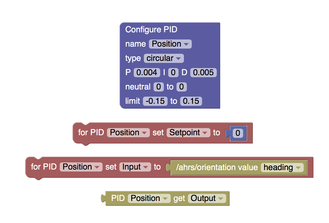
    One fundamental software piece for any robot is the PID controller - the Proportional Integral Derivative controller (see https://en.wikipedia.org/wiki/PID_controller). Adding one to the RoBonnet software stack was always a given. In fact, the software stack has had such a controller for a while, but I've now had chance to provide access to it via Blockly:

    Many PIDs can be created, named, and configured with the setting you'd expect to find. I also added a couple of extras to define a "neutral zone" where the PID output is clamped to zero, and limits to clamp the outputs to low and high values.

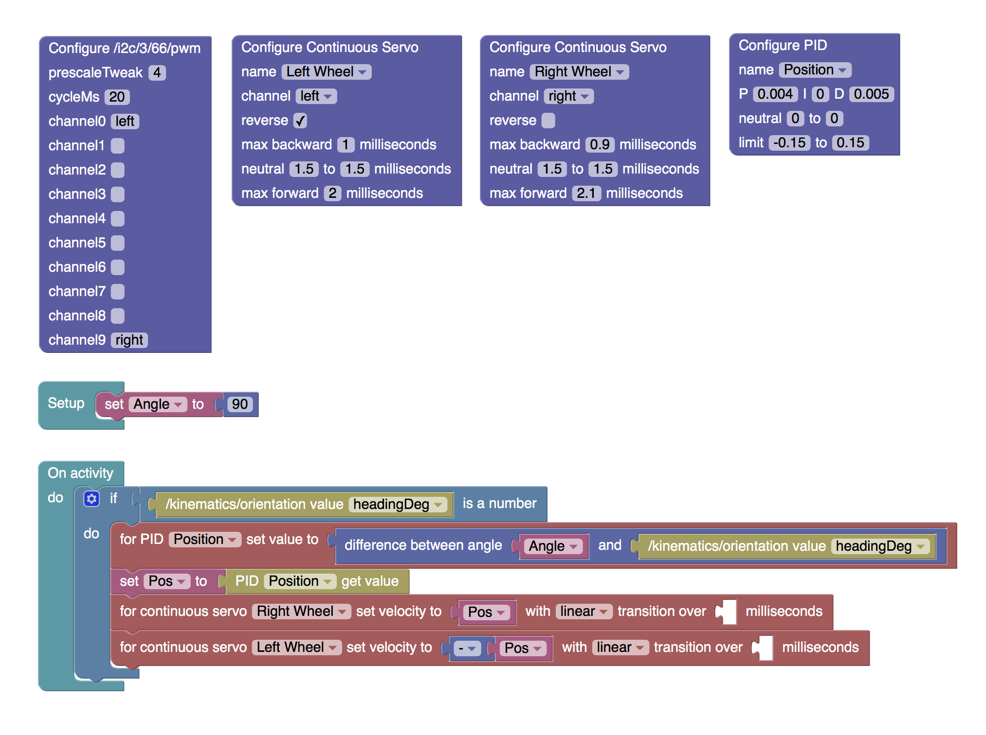
    The following simple control program configures the Rolling Robot Ball to always return to a specific heading (determined by the RoBonnet IMU).

    And you can see the program in action in the video below:

  • ESC Configuration - Take 2

    Tim Wilkinson08/17/2018 at 18:26 0 comments

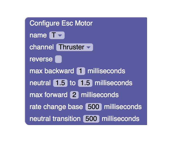
    After some experimentation with the first ESC configuration, it turned out that simply controlling the maximum rate the motor velocity changed was not quiet enough to stop it resetting when rapidly switching from forward to backward; I needed to add a "pause at neutral" time as well.

    The new configuration, seen above, is very like the pervious one except now there's a "rate change base" which controls the fastest rate at which the velocity can change, and a "neutral transition" time which pauses the motor - momentarily - when passing through neutral.

    Of course, I'm testing these values running my motors in air when they will ultimately be running in water. Given that, I expect I can decrease the rate and neutral times to improve robot responsiveness once everything gets wet.

  • ESC Configuration

    Tim Wilkinson08/13/2018 at 18:44 0 comments

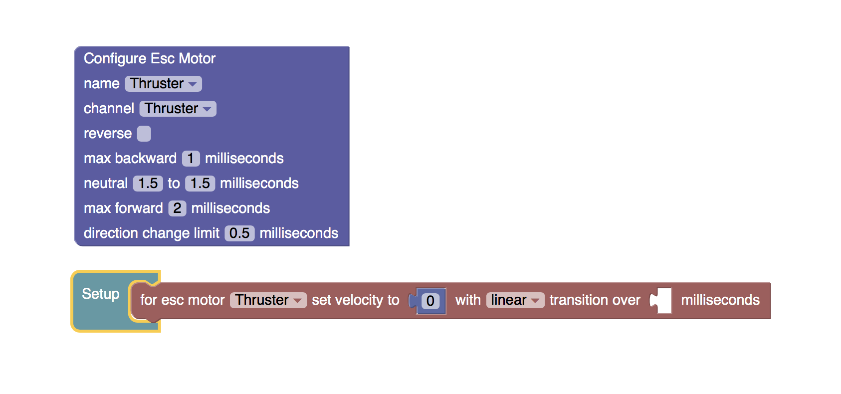
    ESCs can be easily attached to the PWM pins on the RoBonnet. However, there's a bit of software configuration necessary to make them useful.

    Above shows the basic configuration of an ESC Part. The ESC can be configured to have a maximum forward and backward pulse width (in milliseconds) as well as a neutral range - this can vary depending on the ESC being used. In this example the ESC can drive the motor both forwards and backwards although different parameters can be set if the ESC is forward only. A toggle is also provided to switch the ESCs notion of forward and backward which can be useful if the attached motor is reversed (as can often be the case with two-wheeled robots). Finally, a direction change limit is provided. If you've ever tried slamming an ESC motor from forward to backward without going through neutral you'll know how bad an idea this can be (often causing the ESC to reboot or simply fail). This final setting limits how fast this change can be effected to prevent failure.

    The "Setup" block shows how the ESC can be managed once configured. A velocity between -1 and 1 is translated by the ESC software into the appropriate motor motion based on the configuration. Here the motor velocity is just being set to zero which most ESCs require as part of their initialization.

View all 38 project logs

  • 1
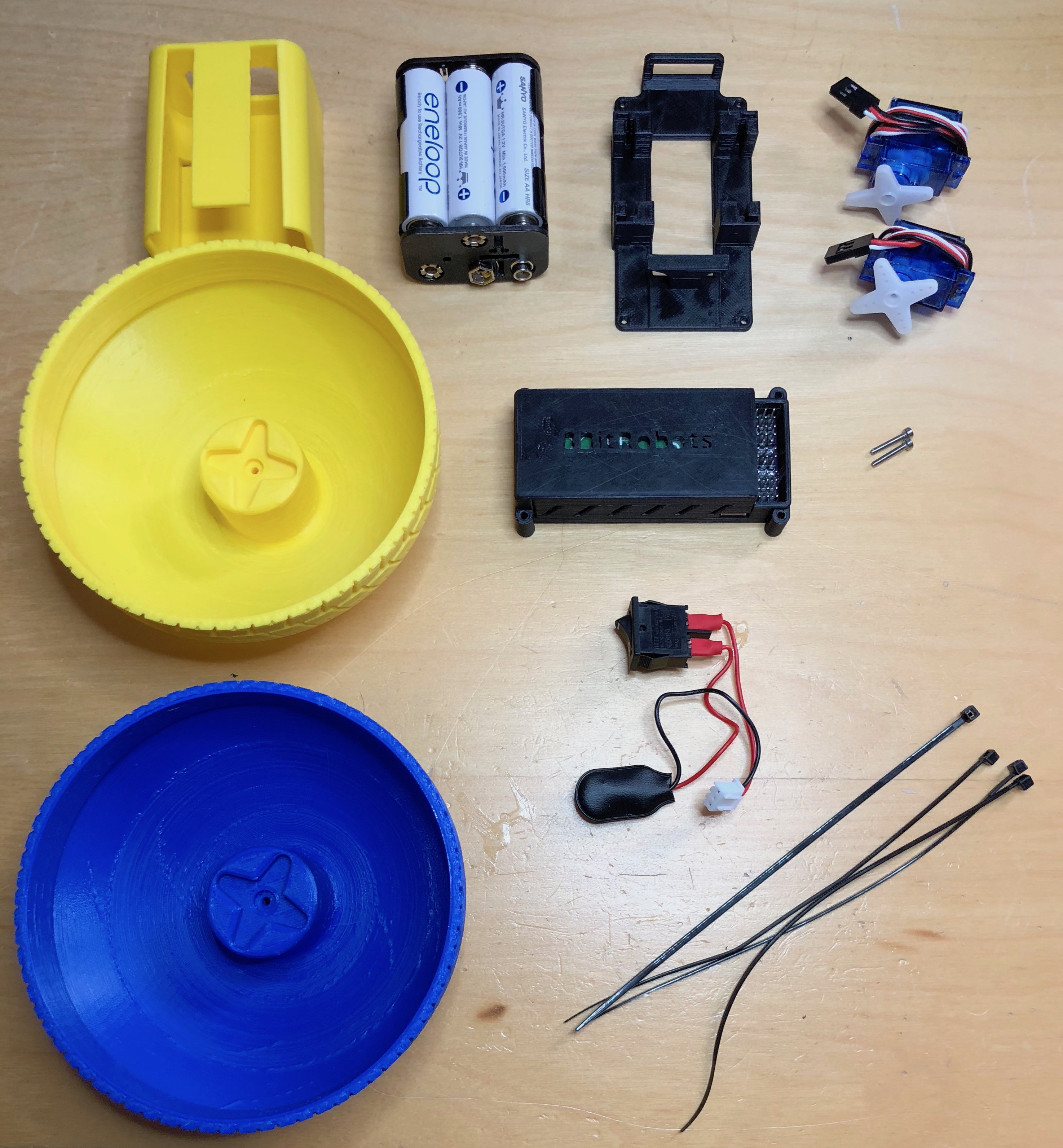
    Ball Robot: What you'll need

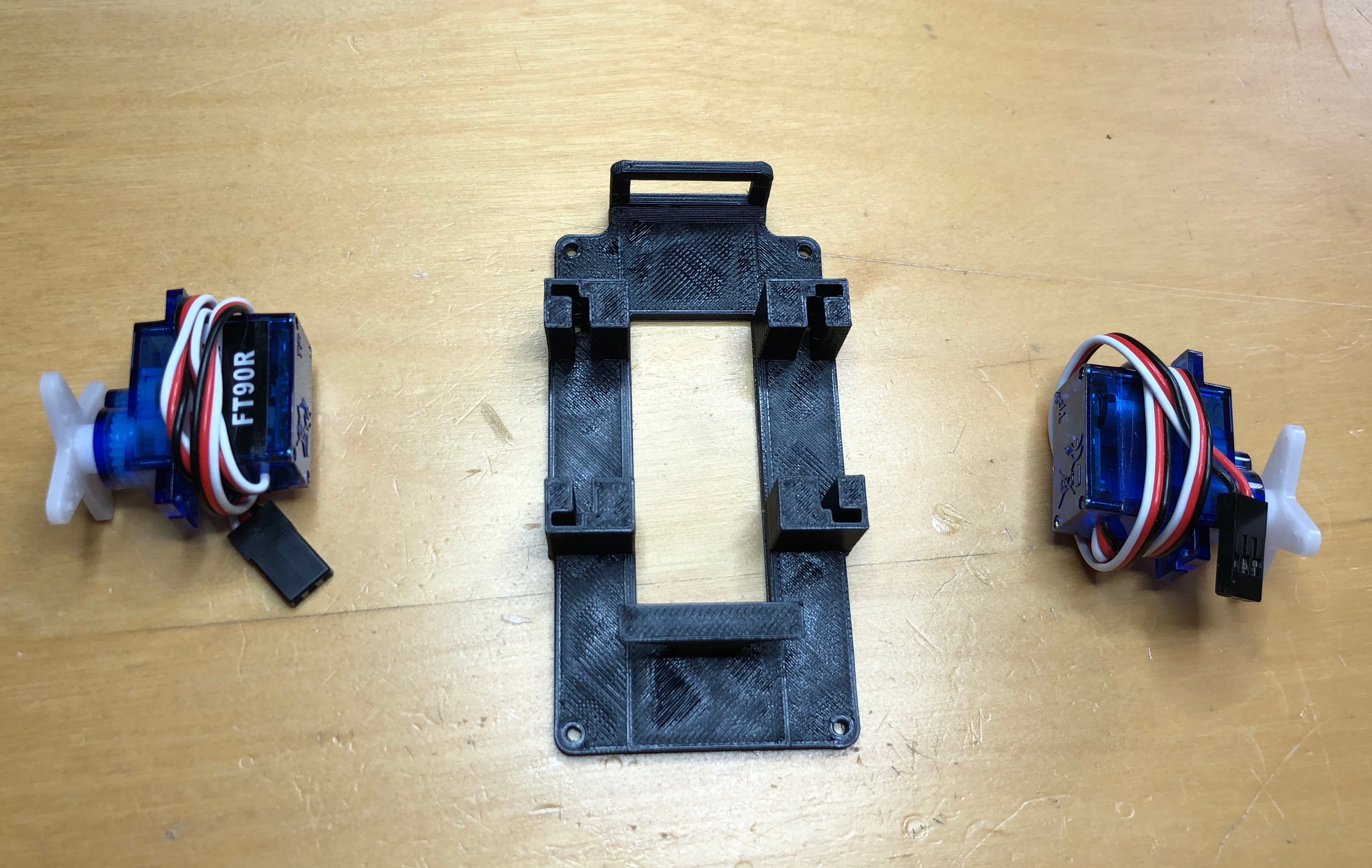
    The simple ball robot is made from the 8BitModule, some 3D printed parts, and a few extra pieces. All parts are shown below.

  • 2
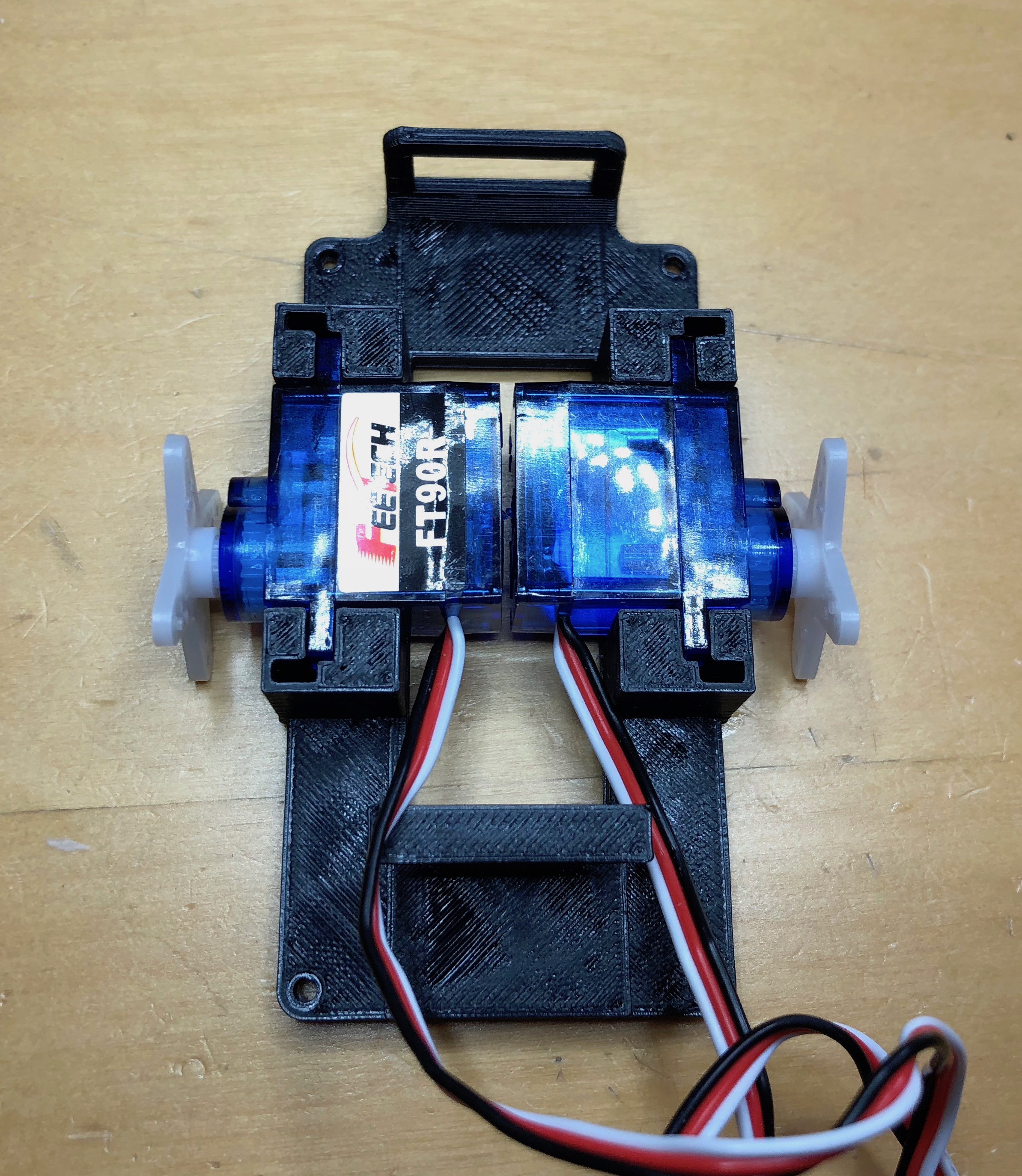
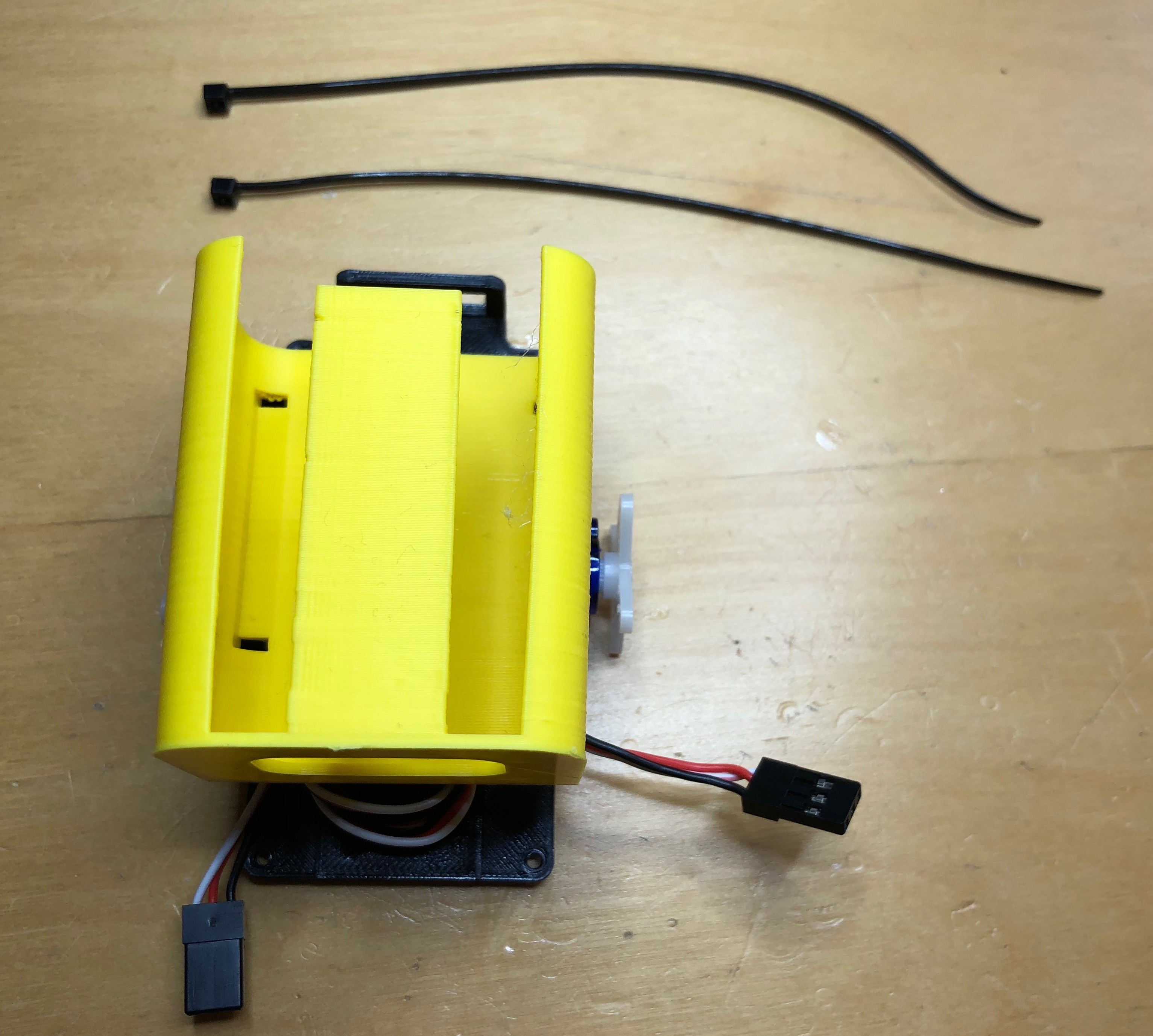
    Mid-frame assembly

    Start by assembling the mid-frame.

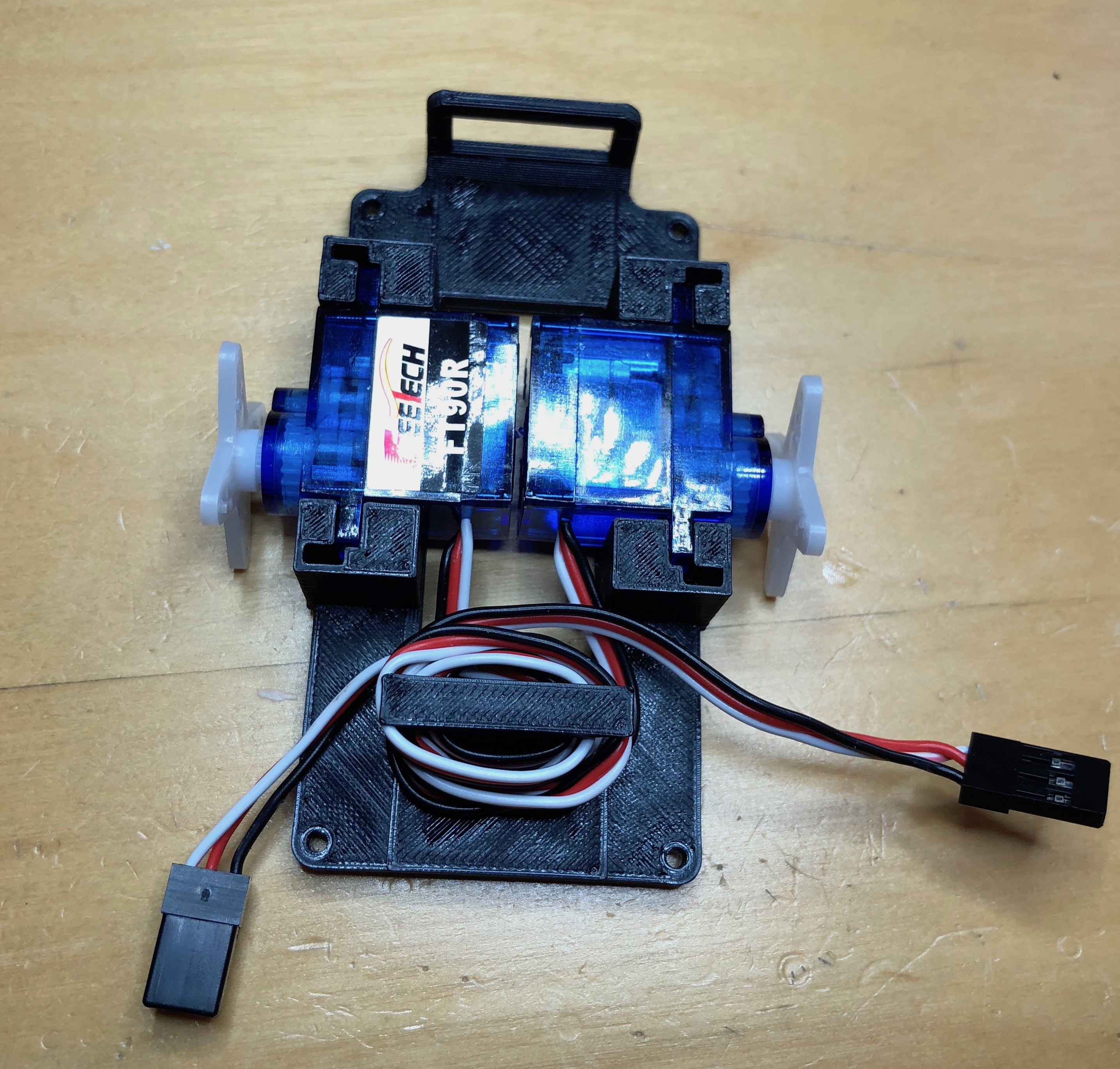
    The two continuous servos fit into the slots in the mid-frame. The servos should be orientated so the servo horns are centered in the frame, one label up and one label down.

    Wrap the extra servo cables around the pillar to keep it out of the way later.

  • 3
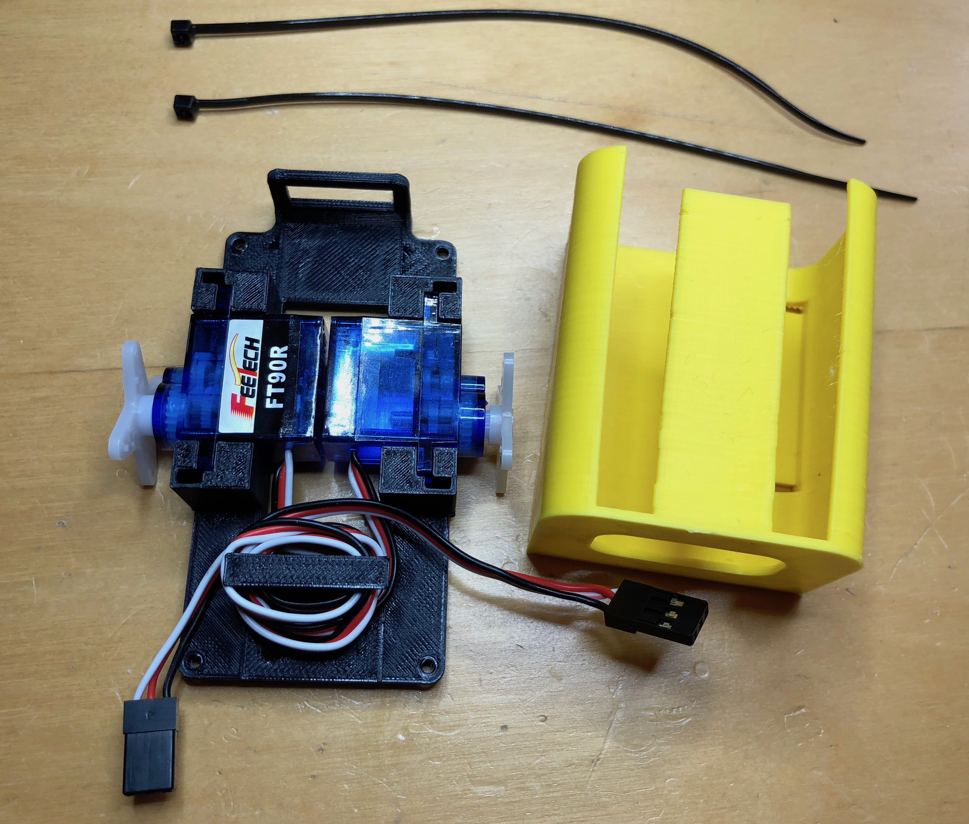
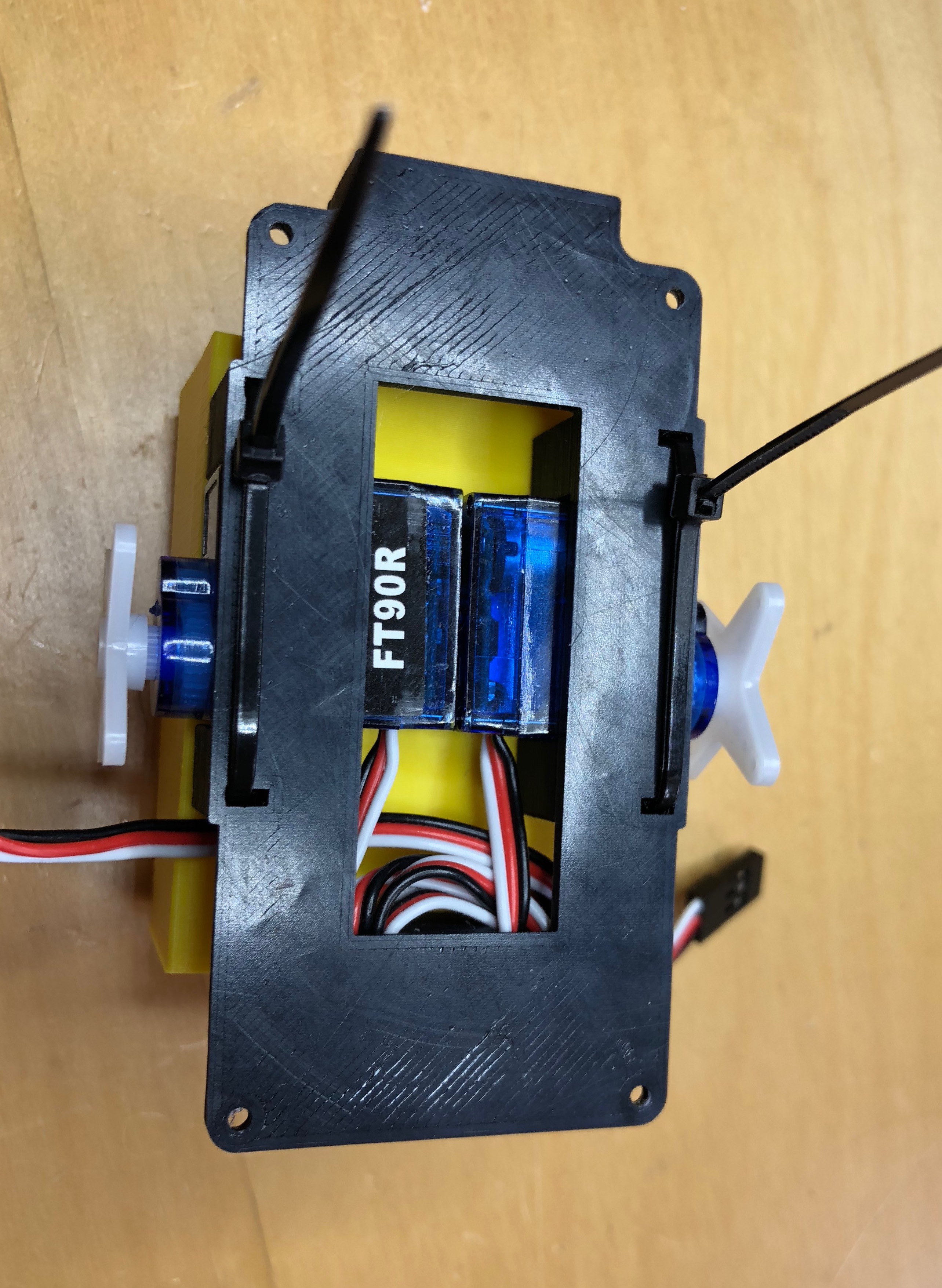
    Attach battery holder

    Next attach the battery holder using two zip ties

    The battery holder goes over the top of the two servos and will secure them in place.

    The opening of the holder should face away from the wiring.

    Now insert a zip tie through the mid-frame, up into the battery holder, then back down through the holder and out of the mid-frame.

    Do this on both sizes to secure the holder and the servos. The zip ties should be "zipped" against the mid-frame and the excess removed.

View all 7 instructions

Enjoy this project?

Share

Discussions

Similar Projects

Does this project spark your interest?

Become a member to follow this project and never miss any updates