 Tim Wilkinson
-
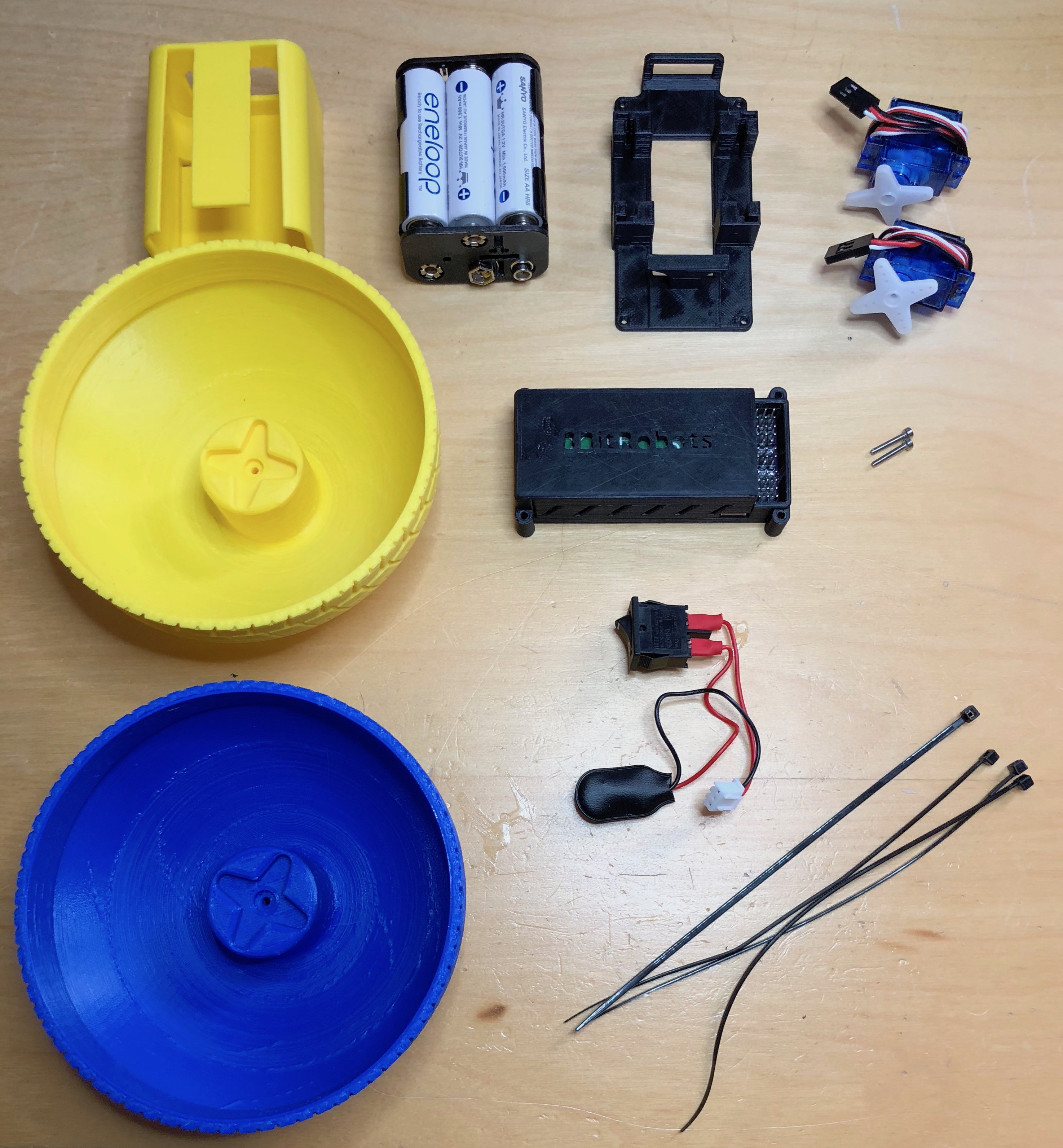
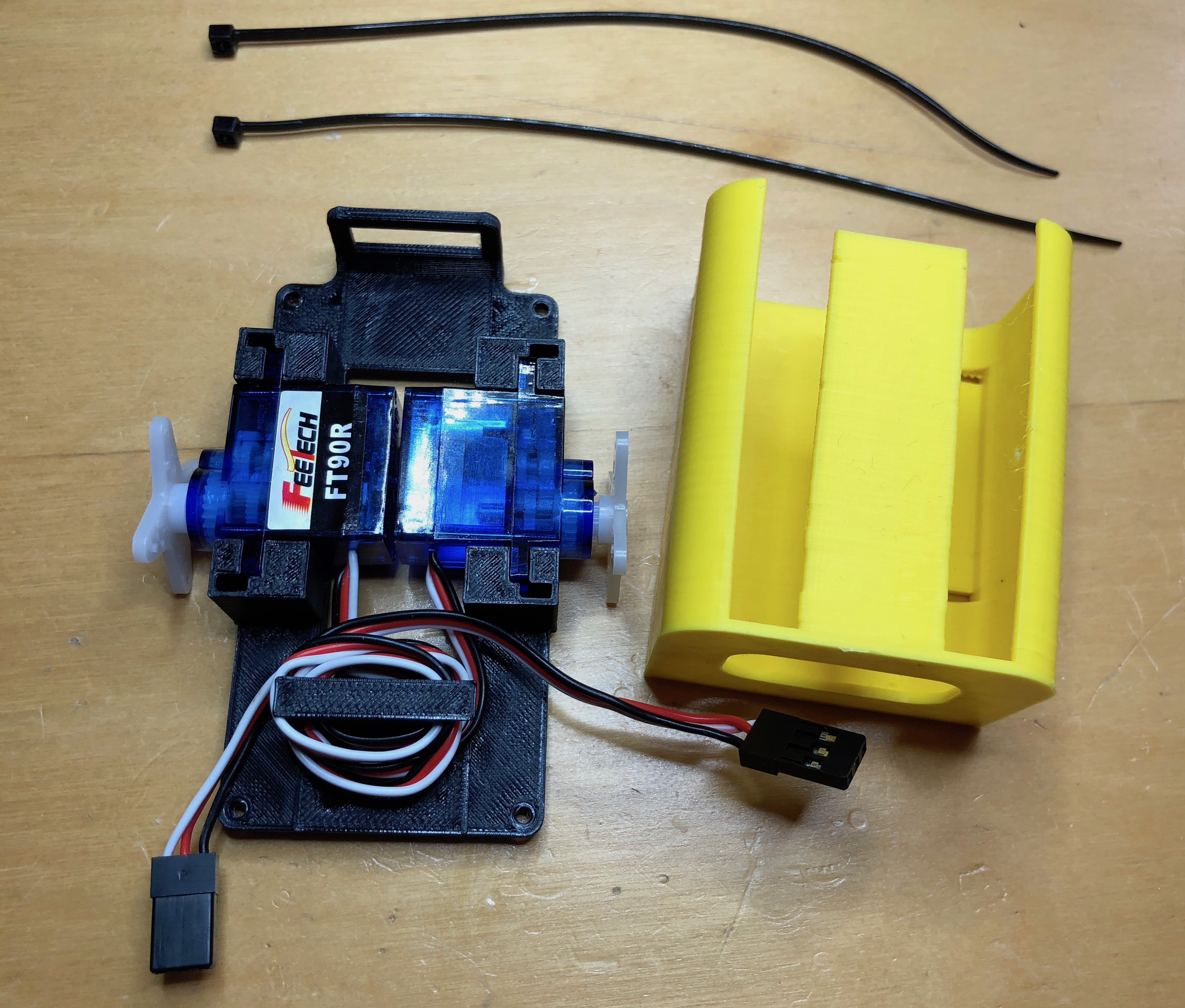
1Ball Robot: What you'll need
The simple ball robot is made from the 8BitModule, some 3D printed parts, and a few extra pieces. All parts are shown below.
![]()
-
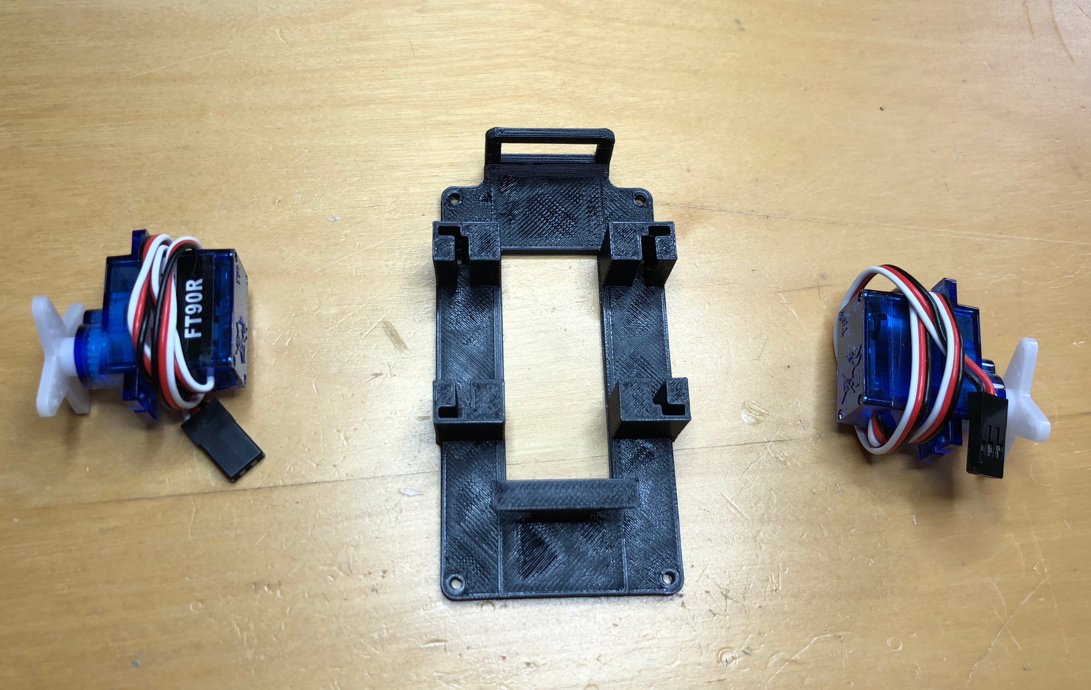
2Mid-frame assembly
Start by assembling the mid-frame.
![]()
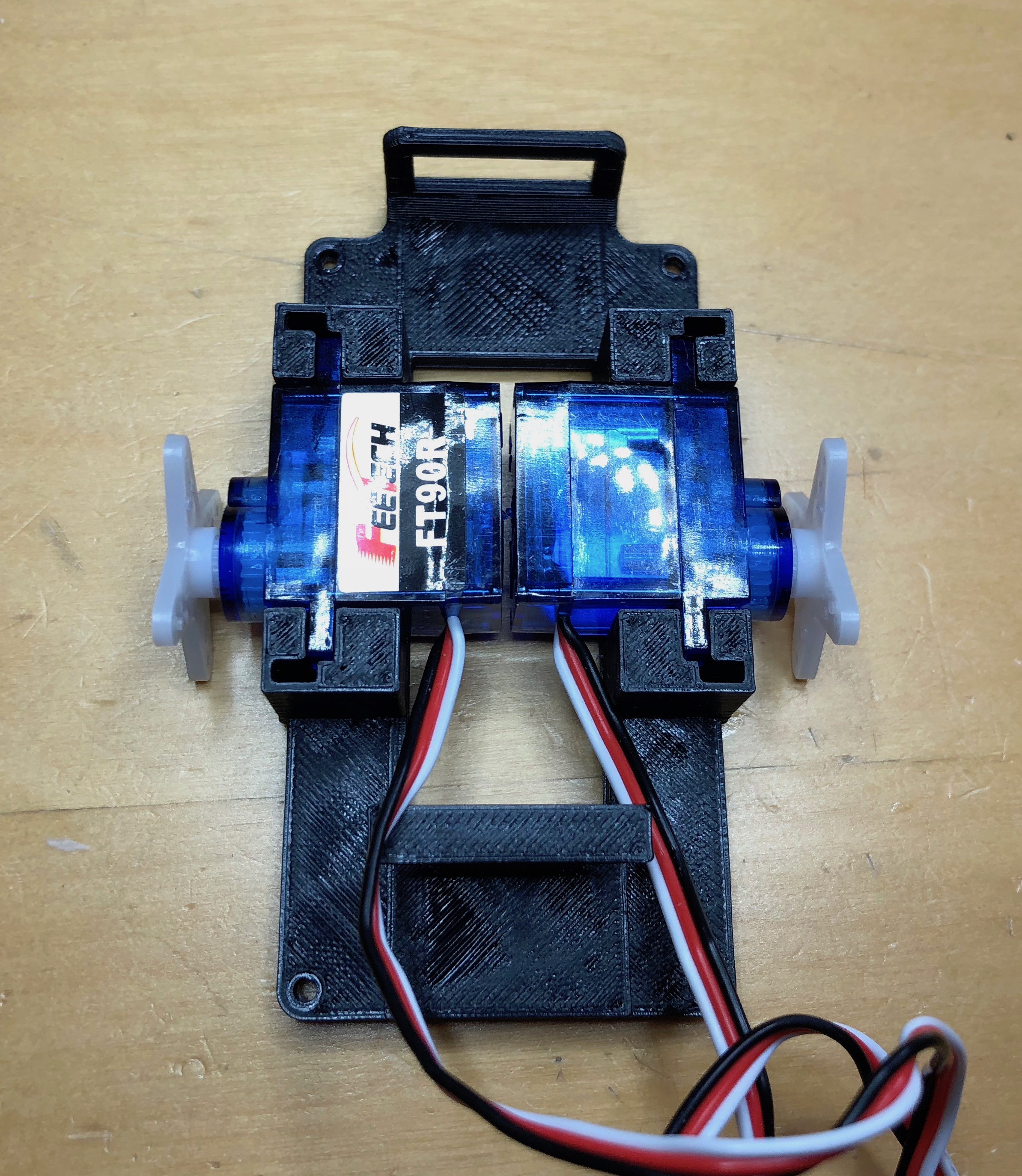
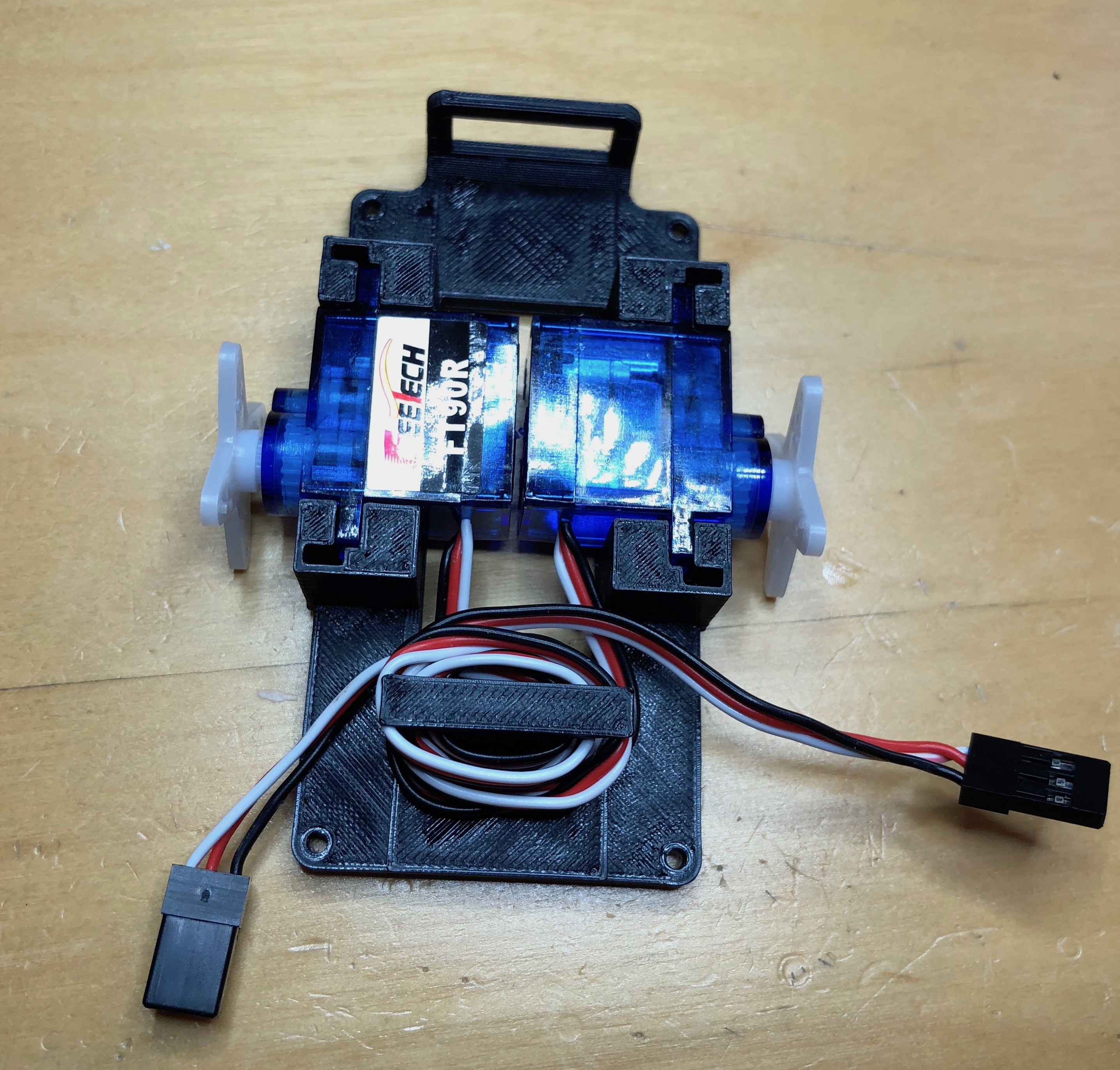
The two continuous servos fit into the slots in the mid-frame. The servos should be orientated so the servo horns are centered in the frame, one label up and one label down.
![]()
Wrap the extra servo cables around the pillar to keep it out of the way later.
![]()
-
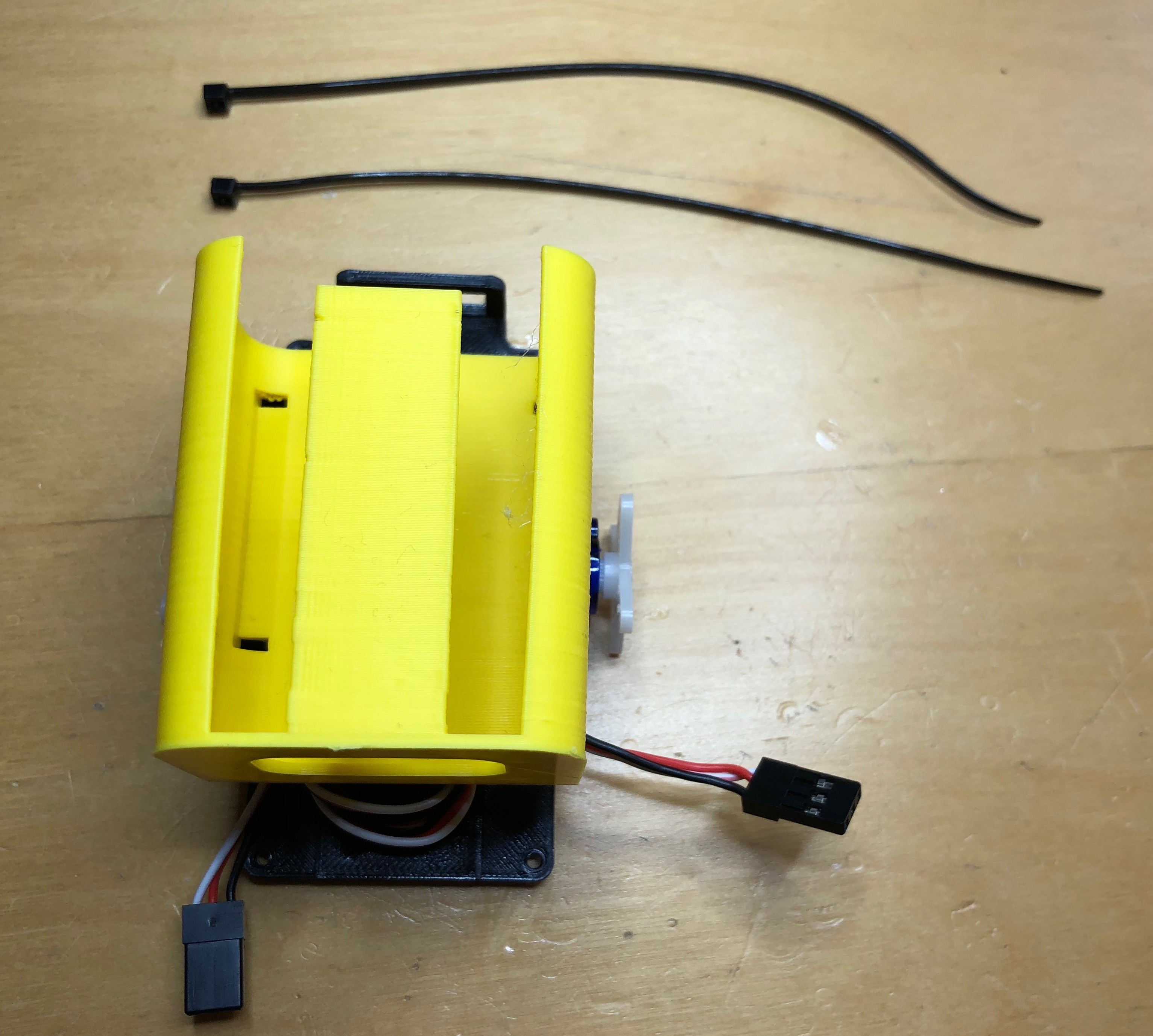
3Attach battery holder
Next attach the battery holder using two zip ties
![]()
The battery holder goes over the top of the two servos and will secure them in place.
![]()
The opening of the holder should face away from the wiring.
Now insert a zip tie through the mid-frame, up into the battery holder, then back down through the holder and out of the mid-frame.
![]()
Do this on both sizes to secure the holder and the servos. The zip ties should be "zipped" against the mid-frame and the excess removed.
![]()
-
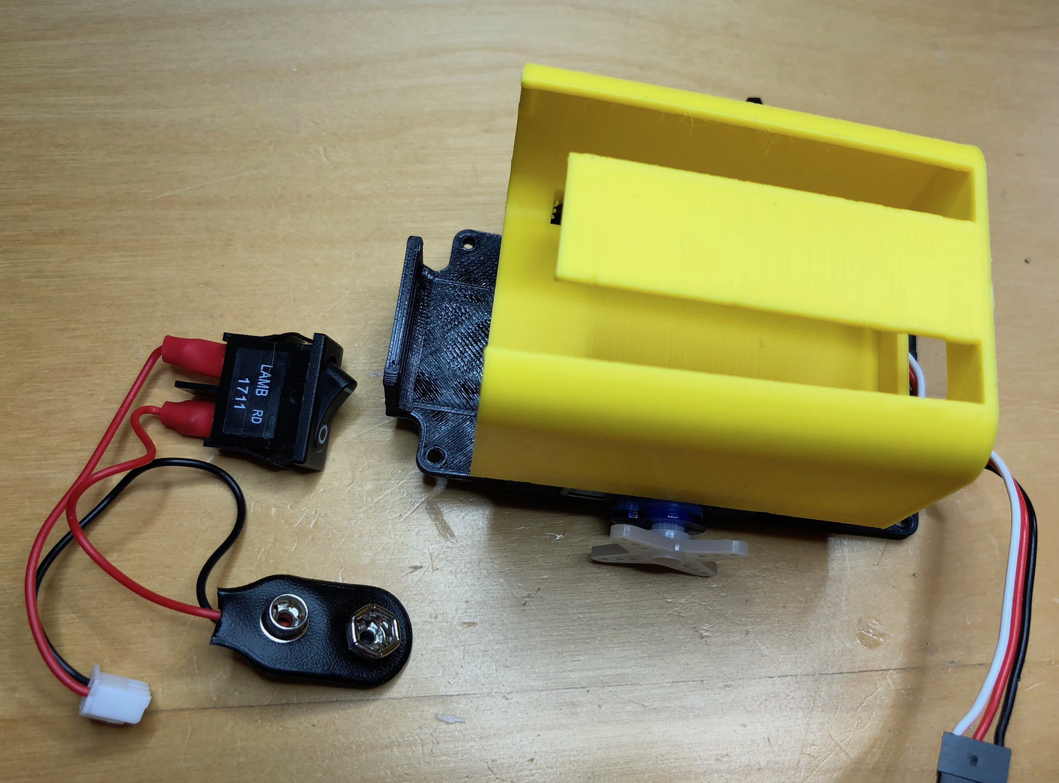
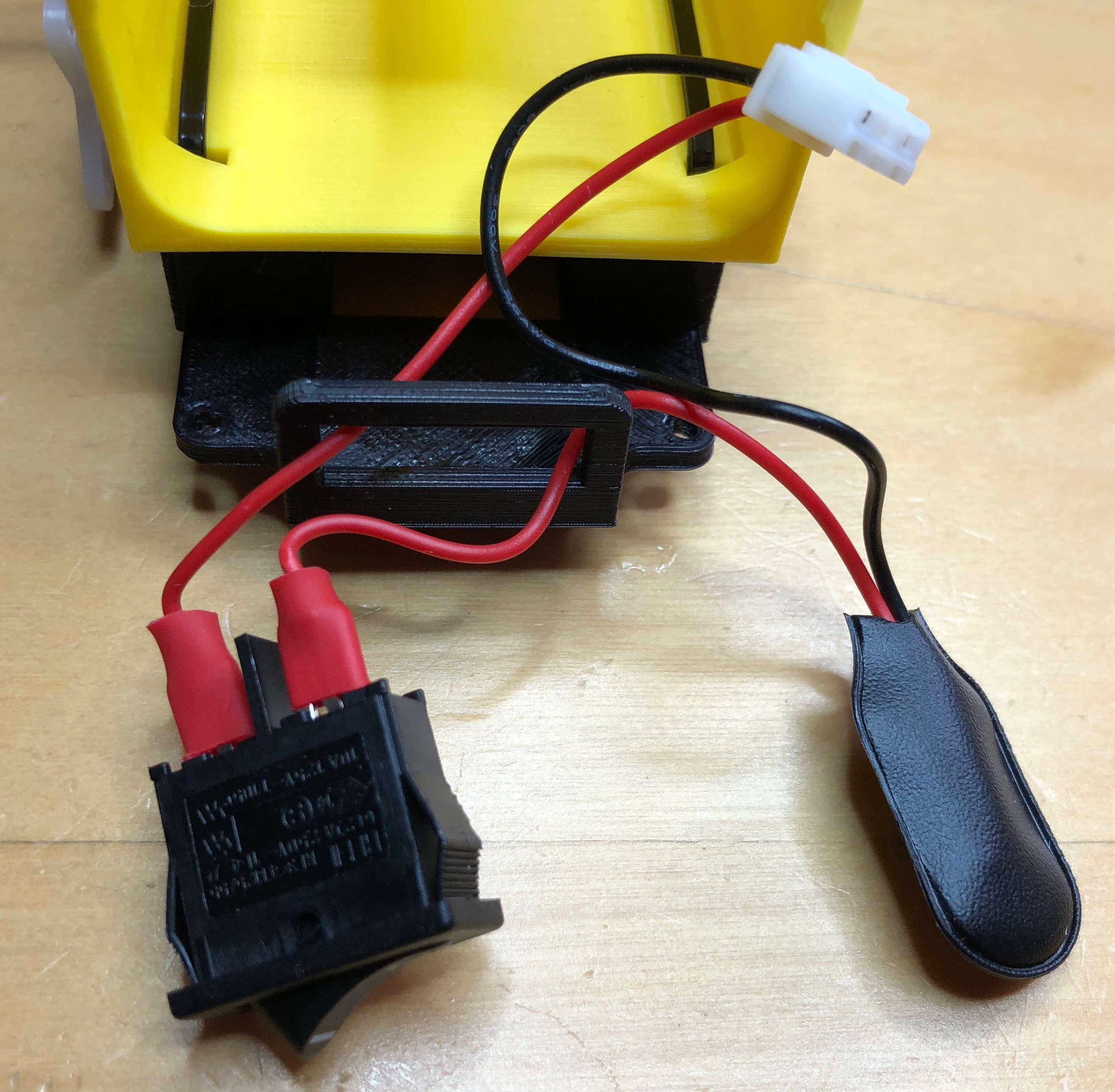
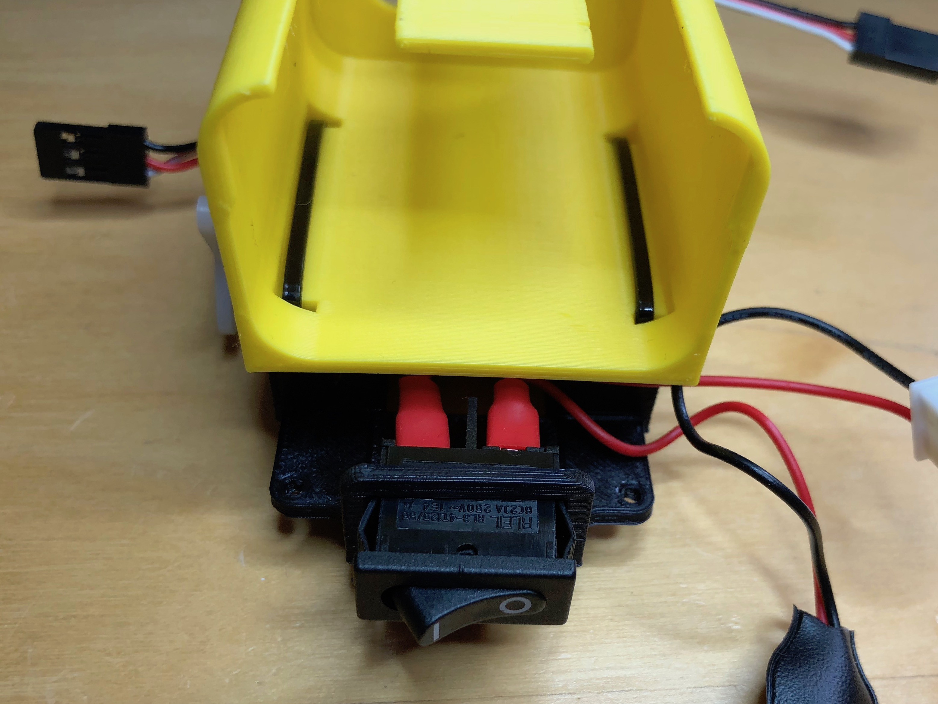
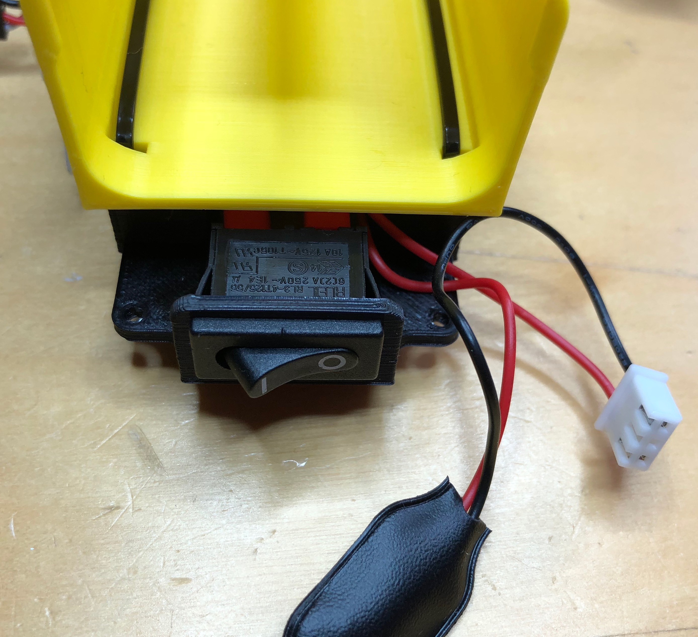
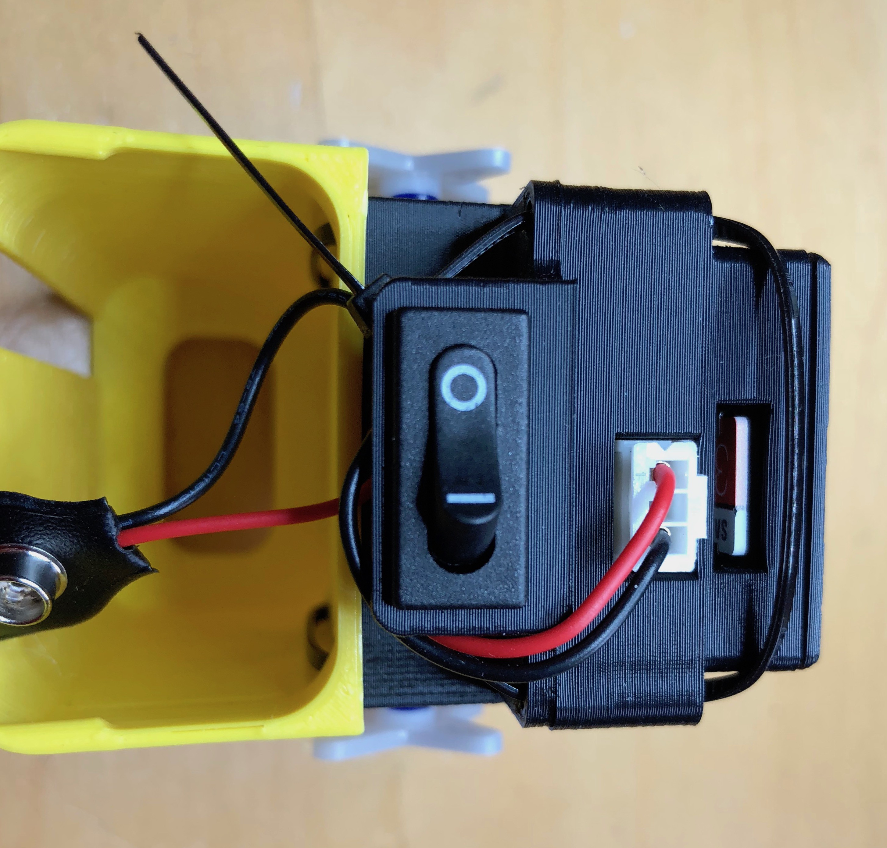
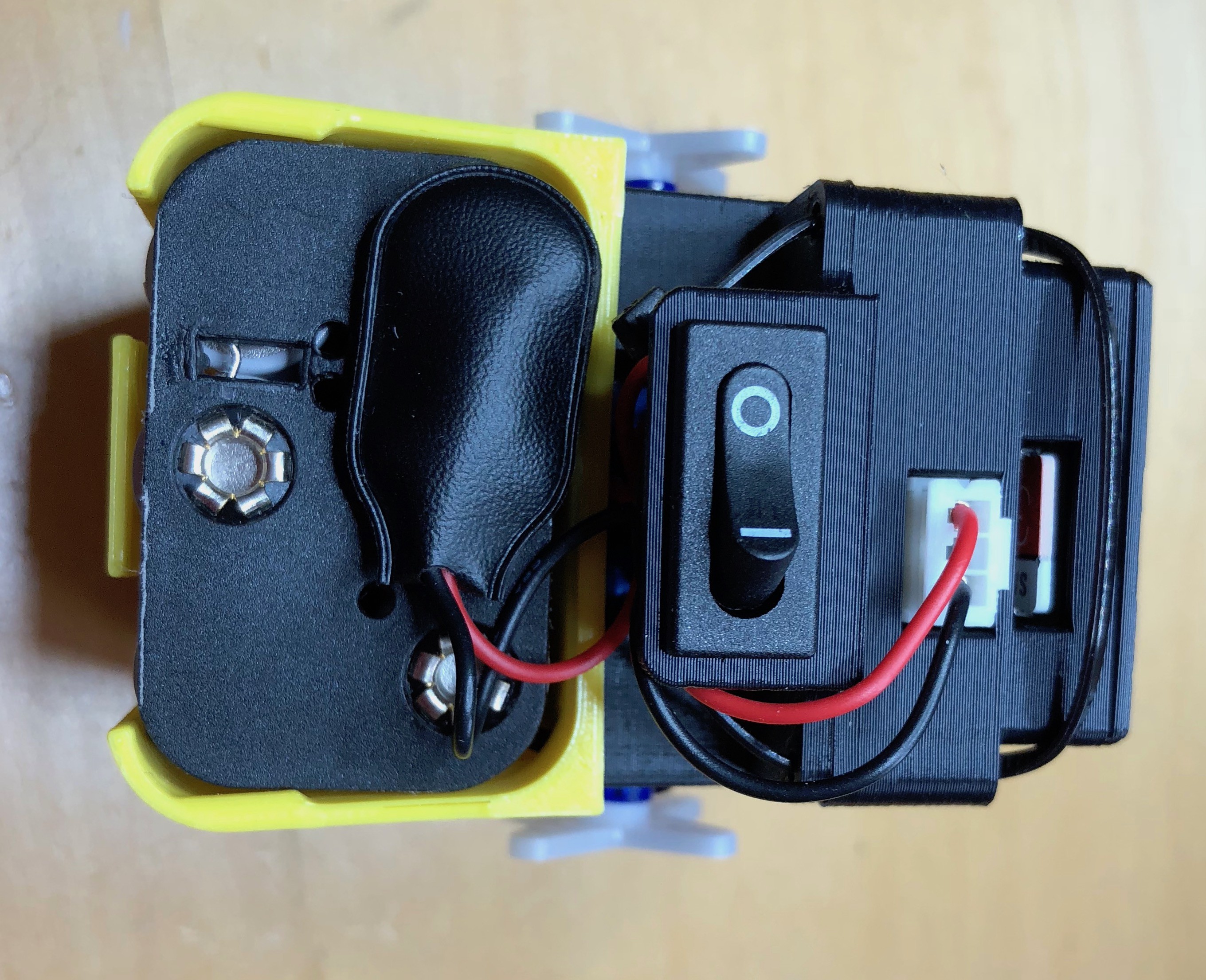
4Power cables
Next add the power cable and switch.
![]()
The pre-made power assembly will push through a hole on the mid-frame into which the switch will clip.
![]()
Push the wires, battery and power plugs through the hole. It will all fit but can be a bit fiddly.
![]()
Once through, push the switch into the hole. It's sized to be tight but the switch will fit snuggly once pushed all the way in.
![]()
-
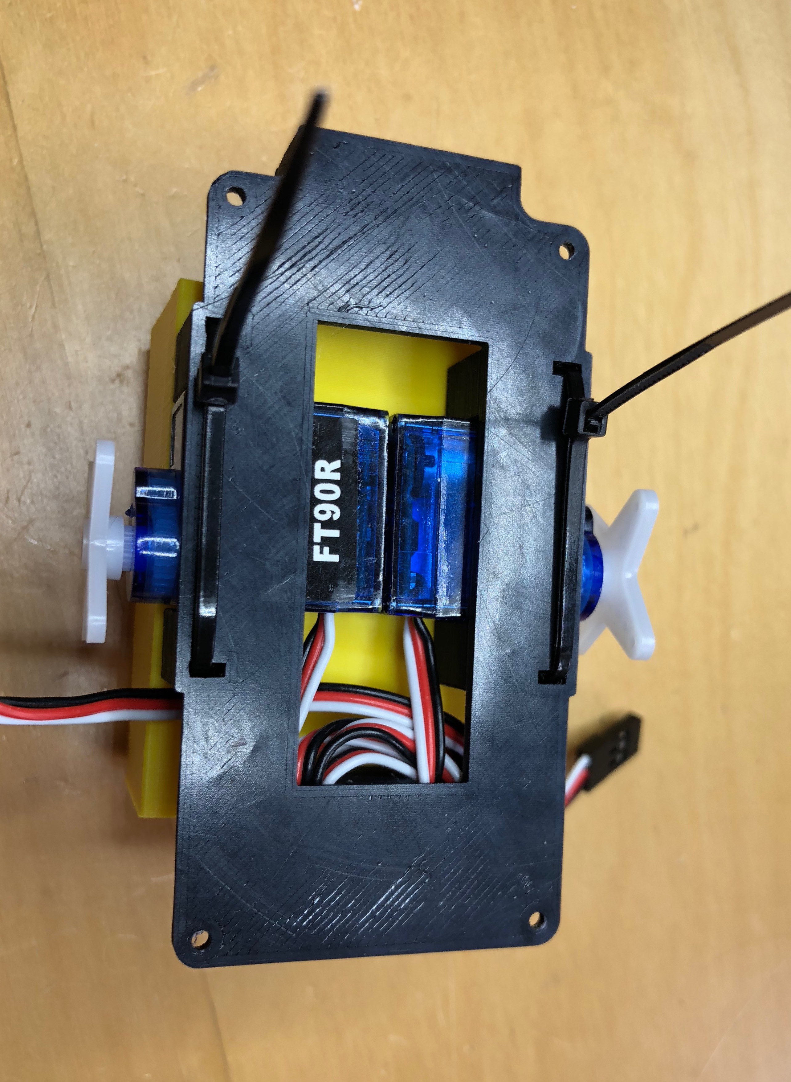
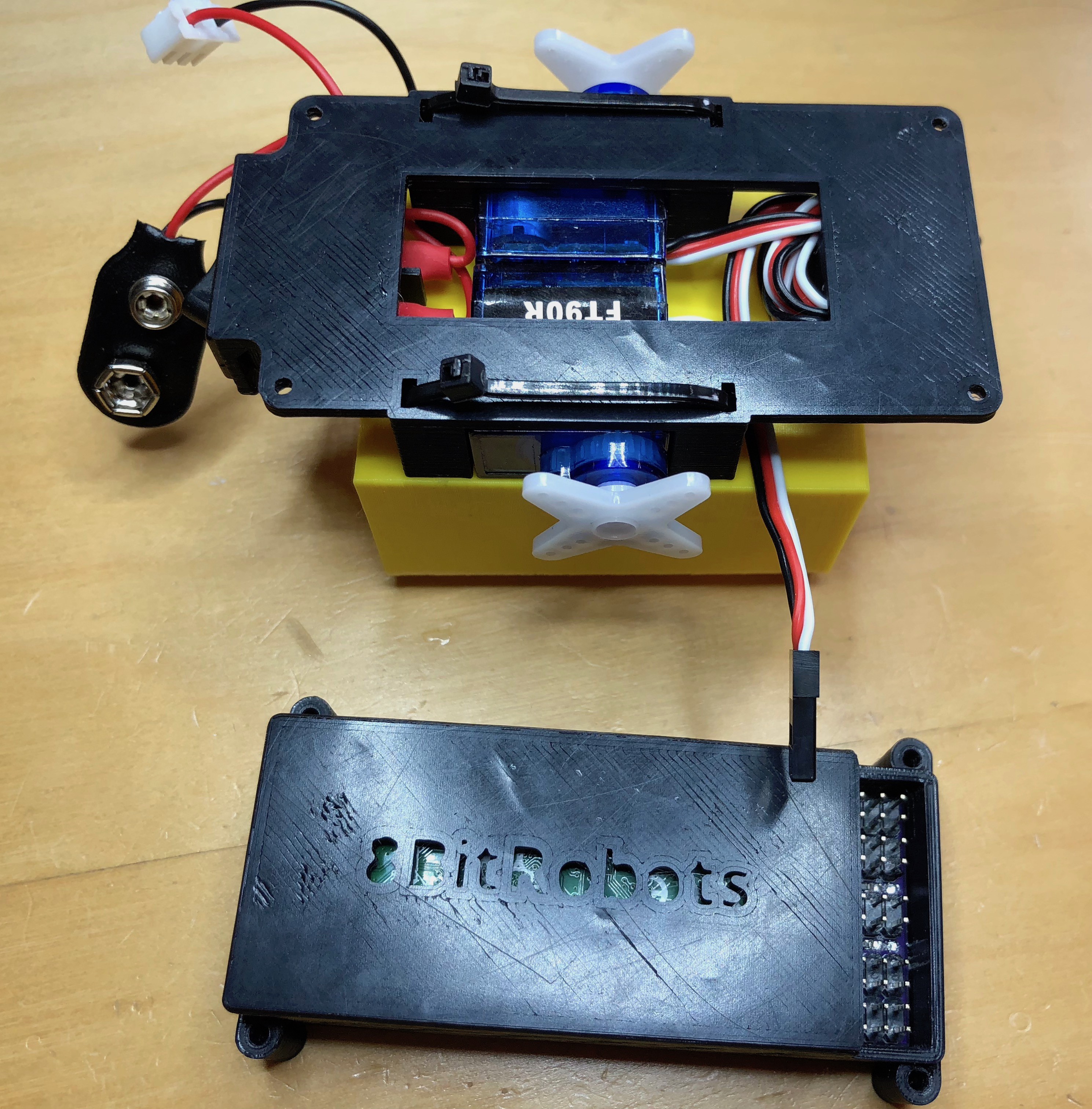
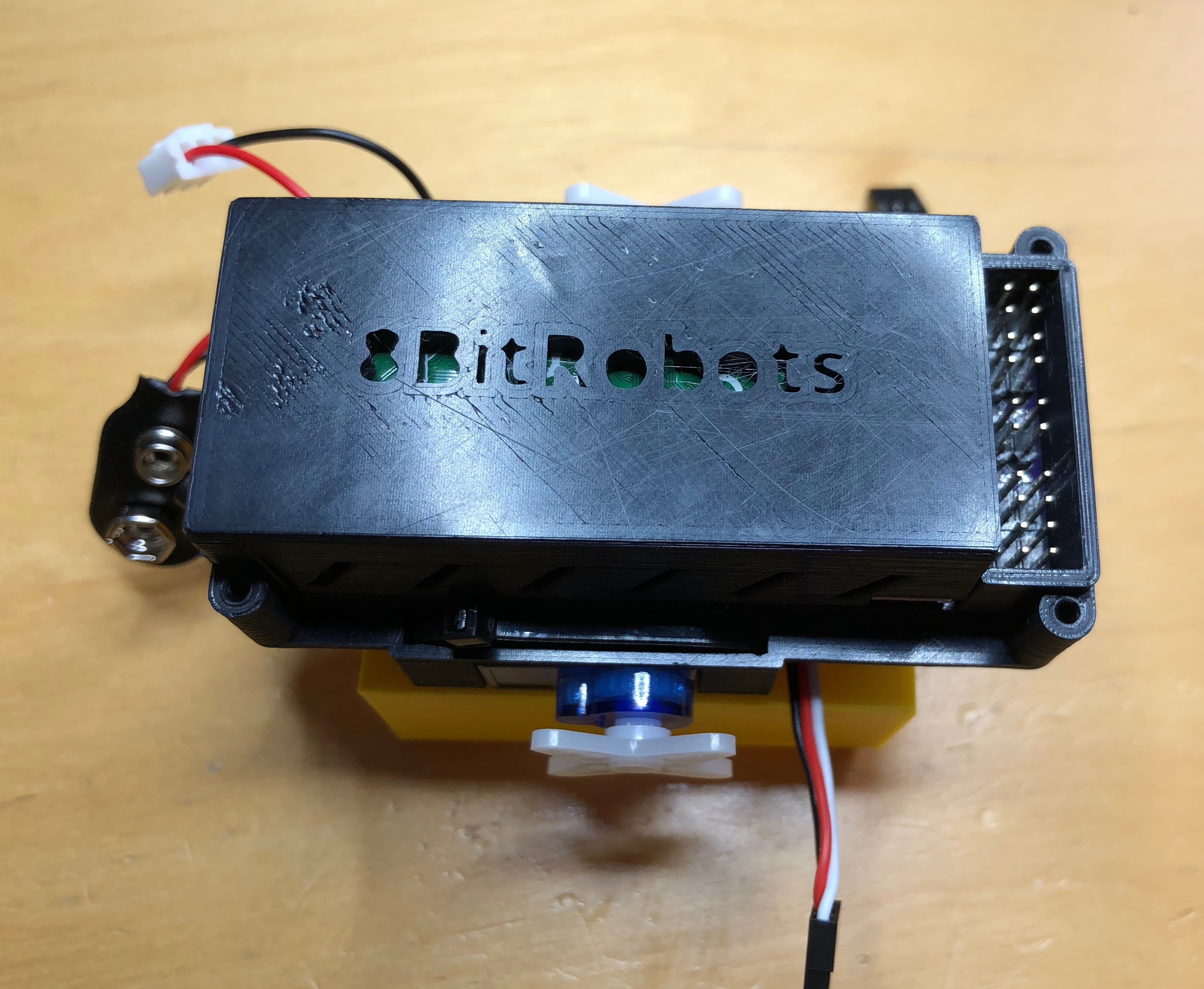
5Attach the 8BitModule
Now attach the 8BitModule (assuming it's already in the default case).
![]()
The module is orientated with the servo connectors towards the servo wires, and the battery connector towards the switch added in the last step.
![]()
The holes in the mid-frame and the module are design for M2 screws, but here we'll just use two more zip ties.
![]()
One on each end.
![]()
-
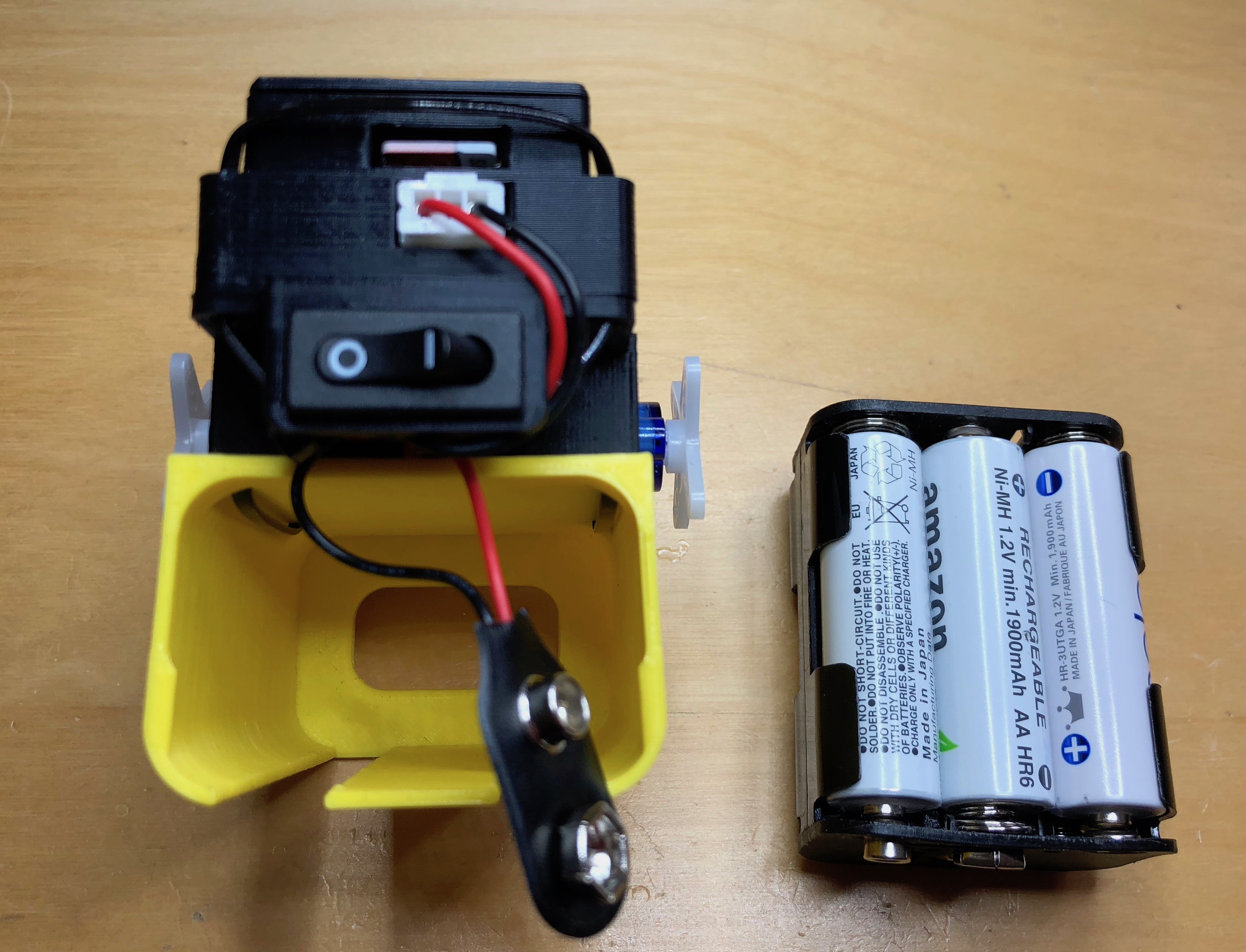
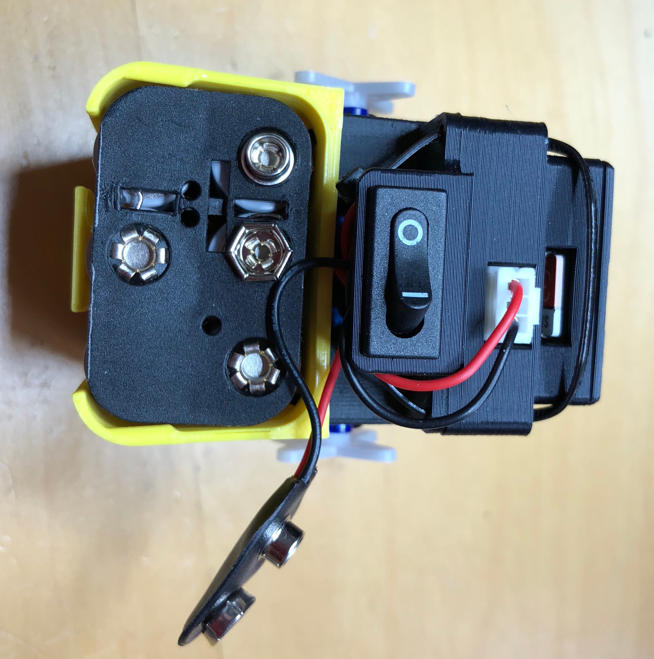
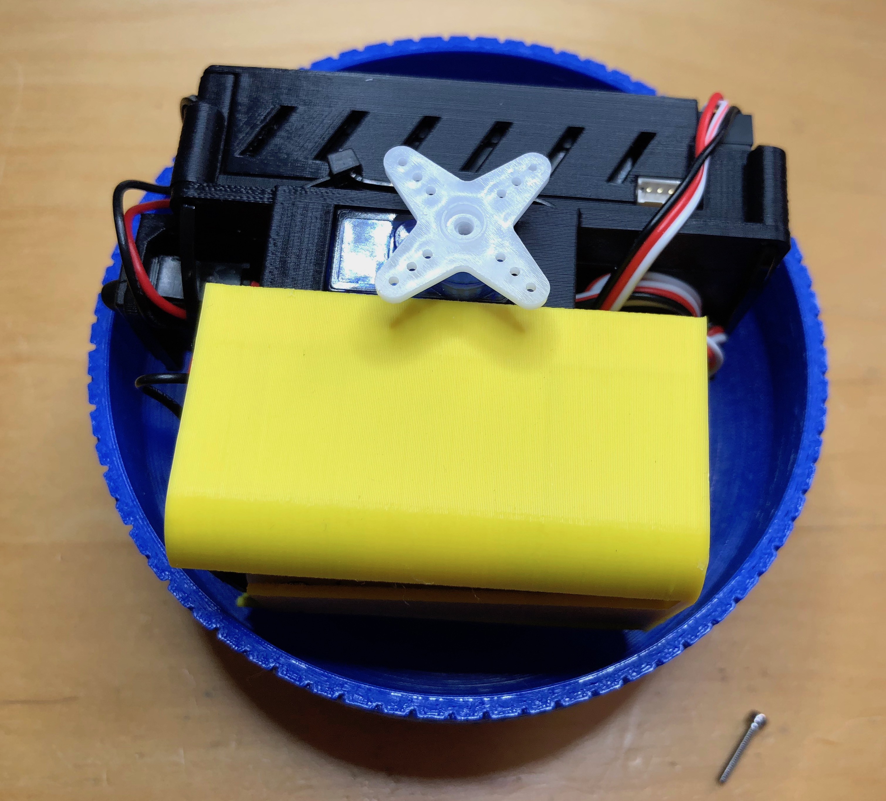
6Add the batteries
Next we'll add the batteries. The ball takes 6 AA batteries (I use rechargeable).
![]()
First plug the power connector into the 8BitModule, then slot the batteries into the 3D printer holder. The shape of the holder should stop the batteries from falling out.
![]()
Finally, with the power switch off, attach the cable.
![]()
-
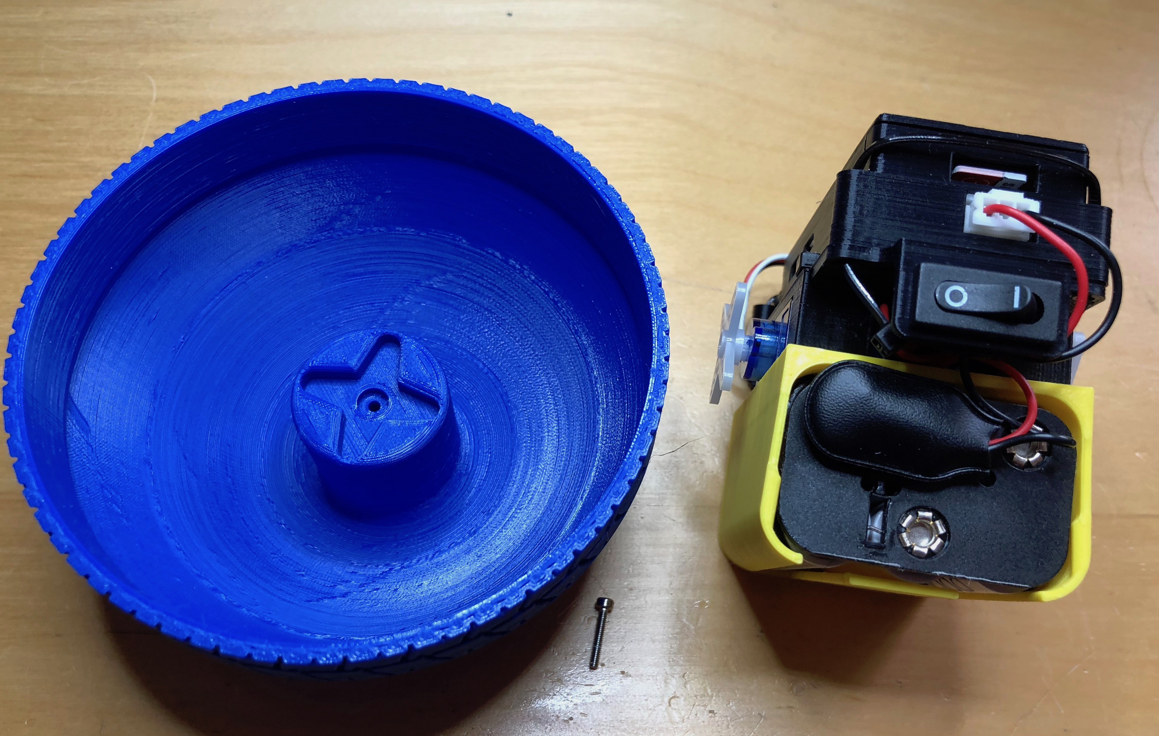
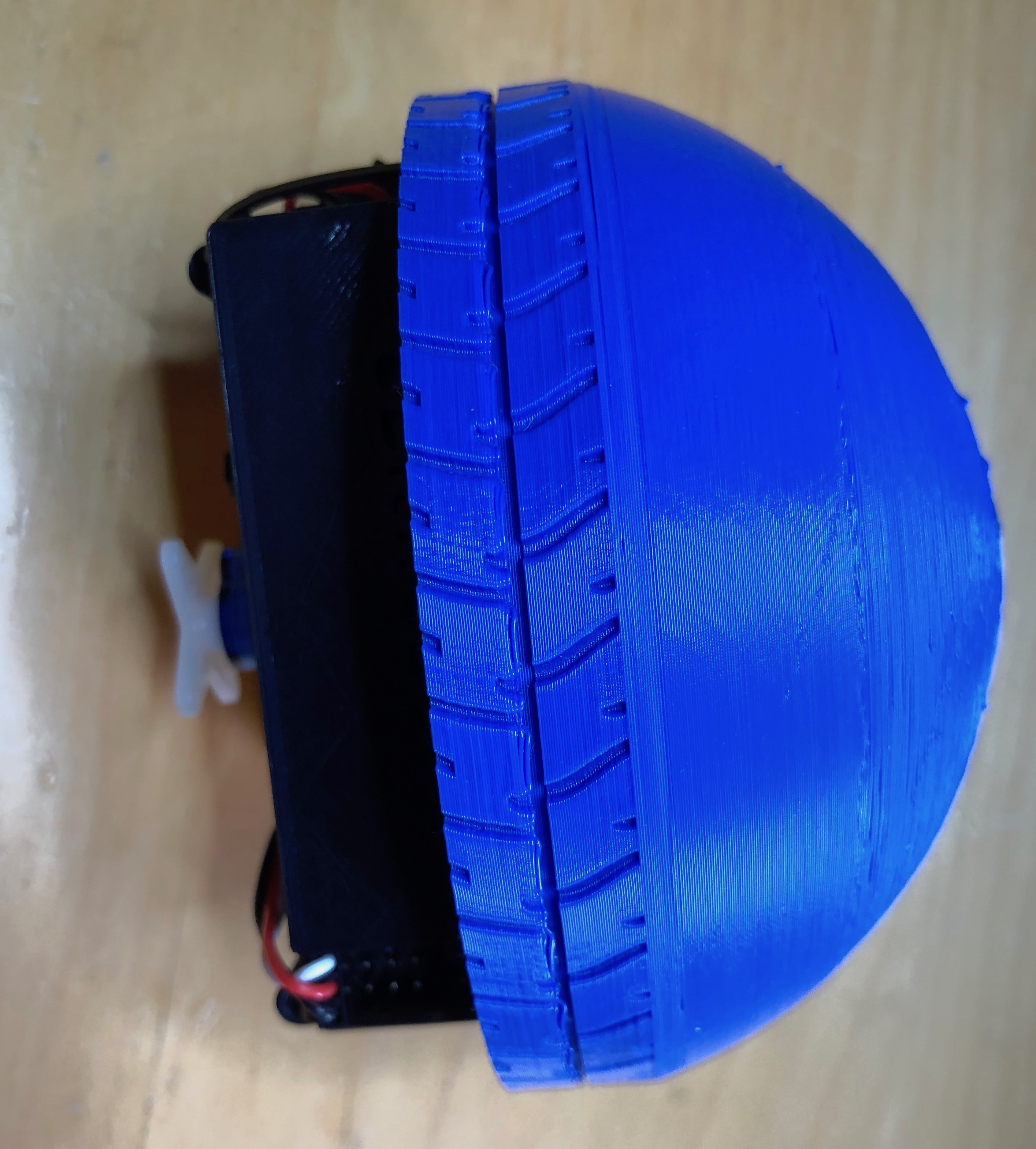
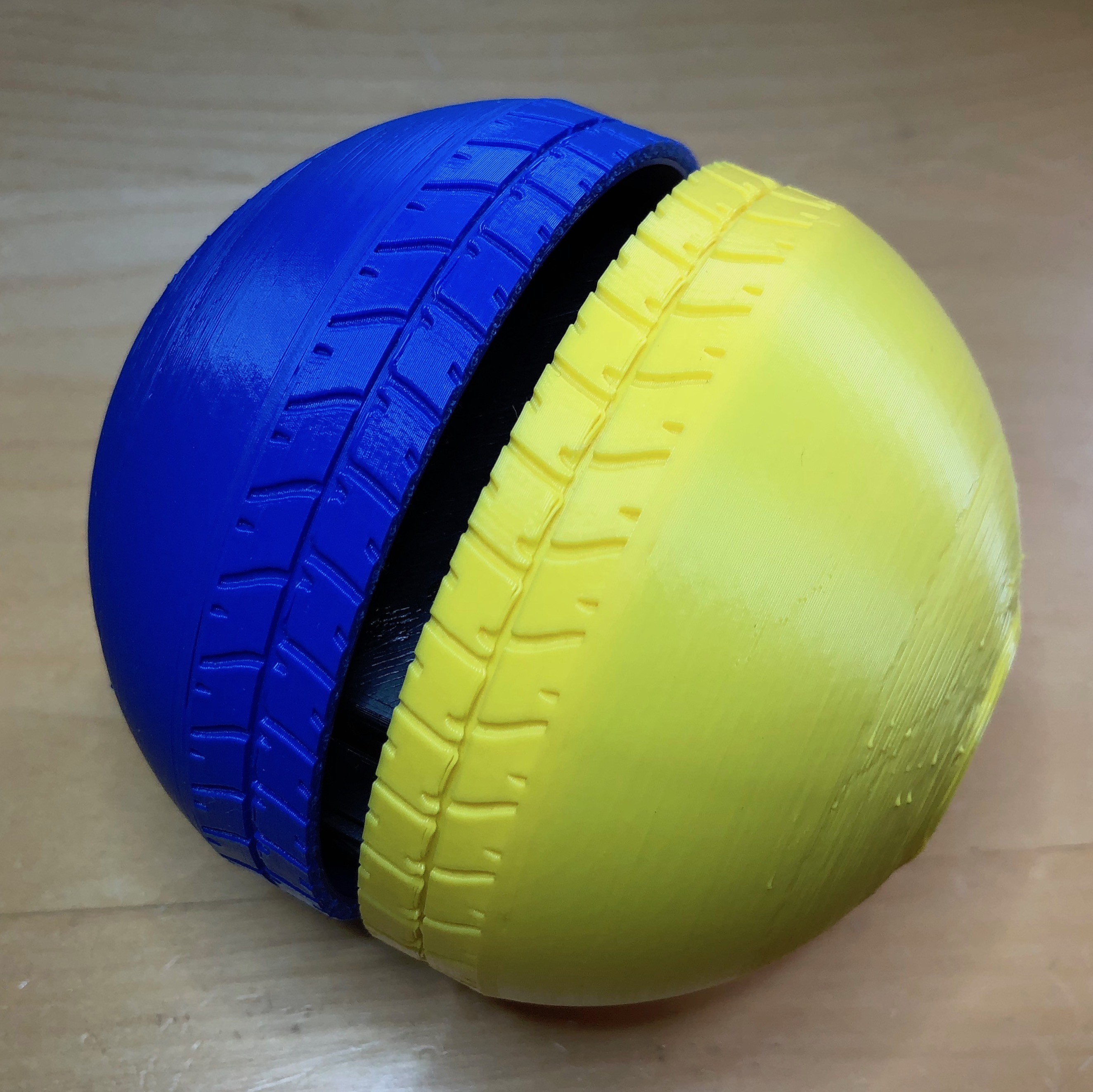
7Add the Wheels
Lastly, add the wheels. Unlike everything else, the wheels must be screwed onto the continuous servos using two M2 bolts (nothing else would secure them successfully).
![]()
Each printed wheel has a cross shaped depression into which the servo horn will slot.
![]()
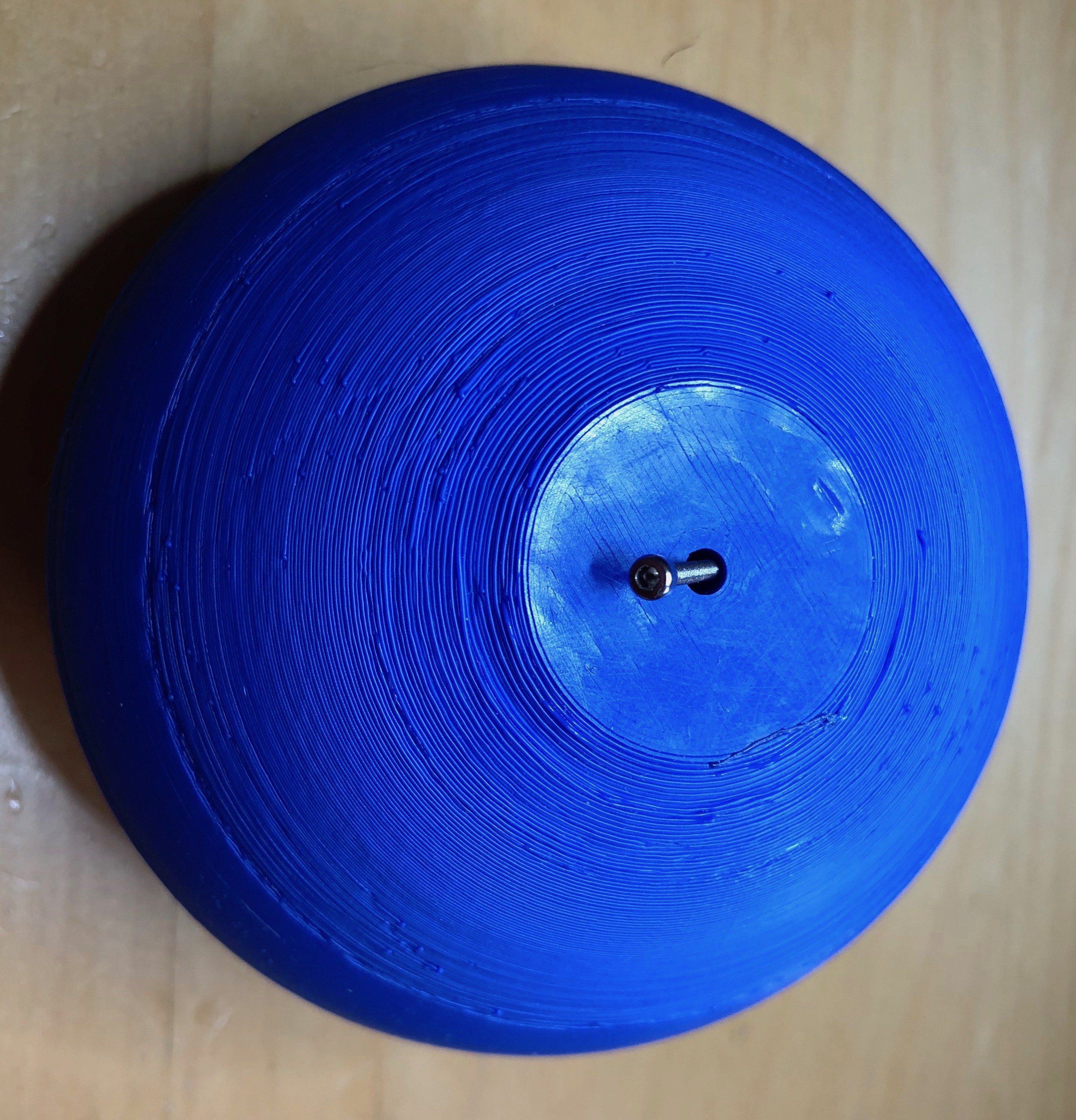
It can be tricky so align them correctly, but you will feel the two pieces come together correctly. Once mated, use the bolt to secure.
![]()
It doesn't matter which wheel goes on first, although obviously once the wheels are attached you can no longer switch out the batteries without detacting them; so make sure they're fully charged.
![]()
Finally, attach the second wheel. They are not design to meet, but rather leave a small gap between them to allow tiny fingers (or probably a screw driver) to access the power switch.
![]()
All done!
8BitRobots Module
A common hardware, software and 3D printed module to enable fun, educational robots anyone can print and program.


Discussions
Become a Hackaday.io Member
Create an account to leave a comment. Already have an account? Log In.