Tim Wilkinson
-
RoBonnet v0.2
04/25/2018 at 21:17 • 0 commentsRoBonnet v0.2 was design to do a full hardware test, except for the power supply part (more on that later).
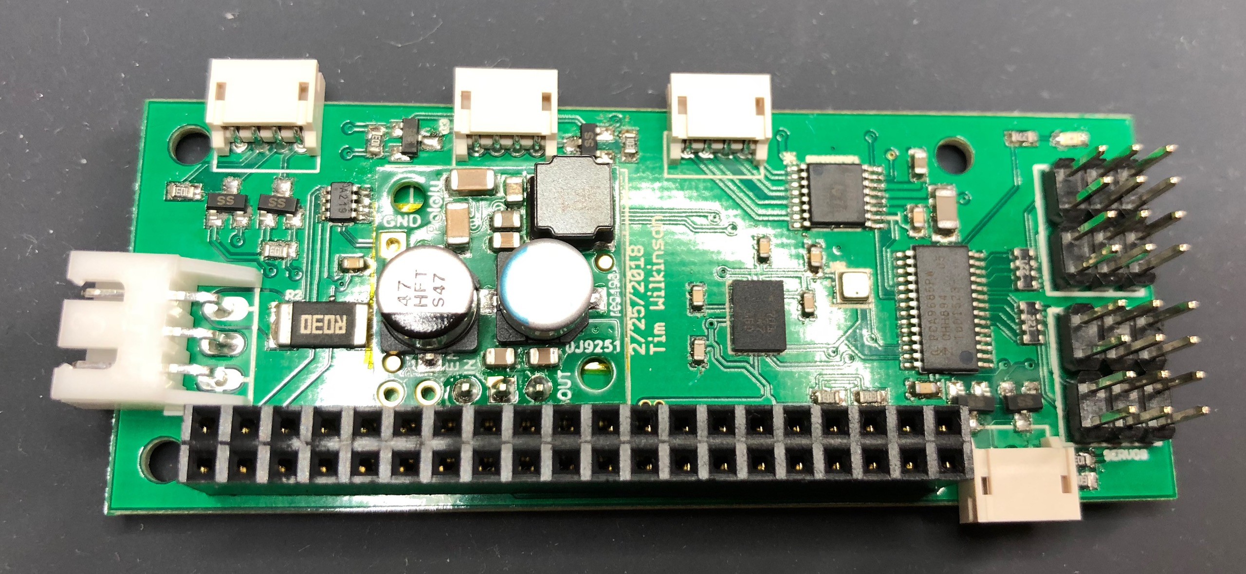
![]()
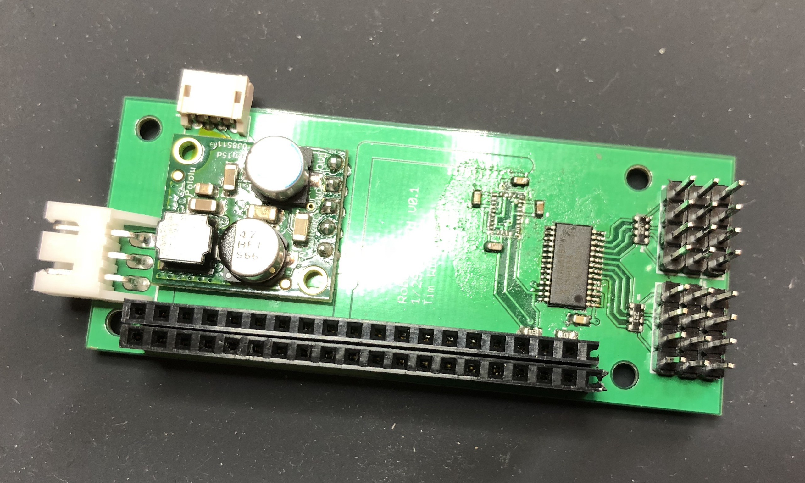
Starting top/left you can see connectors for TTL serial (5V with level shifters because the Pi is 3.3V). encoder inputs (3.3V-5V tolerant), 2 channel DRV8833 h-bridge (5V), 8 PWM channels (5V signals with 5V power), I2C (3.3V-5V tolerant without pull-ups), Pi connector, and power input (6V to 24V).
The board also hosts a BNO055 IMU, a BMP280 pressure/temperature sensor and an INA219 power monitor.
Note that all the I2C devices on the board (and the external connector) are attached to the i2c-3 bus on the Pi. If you've never heard of this, it's the software-based i2c implementation available as part of the Linux kernel. This is used rather than the hardware i2c implementation because that's just broken and has been on every Pi ever. The Broadcom chips used in Pies have a bug preventing them from working with i2c devices requiring clock stretching; and the BNO055 needs this. This bug is ancient and why it's never been fixed in new firmware is a mystery. Thankfully Linux's soft i2c device comes to the rescue.
This prototype was a complete success with everything working as expected (I know!).
The final unknown is the power module which is new territory for me; I've always used other people modules in the past. My first attempt will be with the MP2315; wish me luck.
-
Enclosure
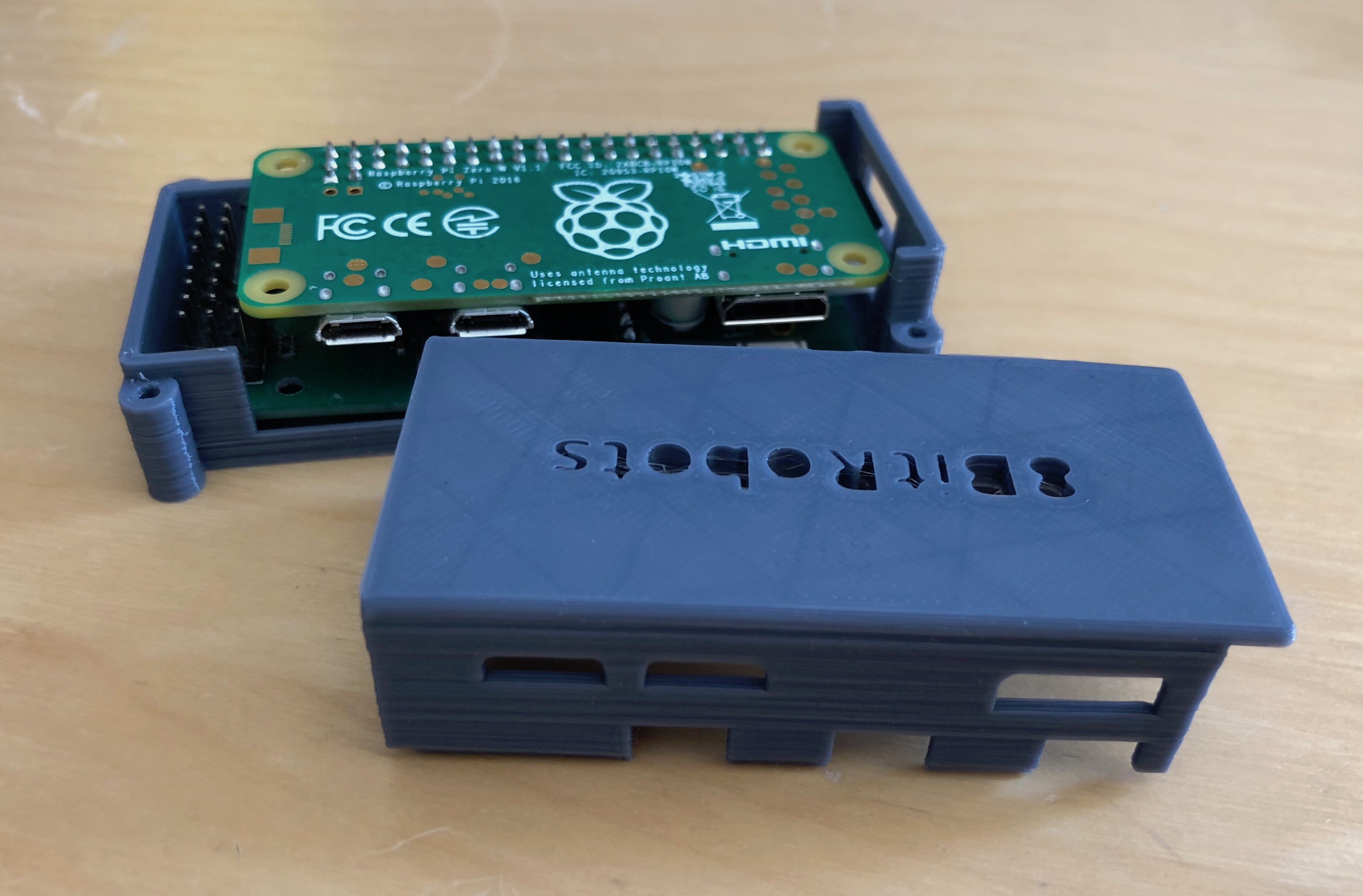
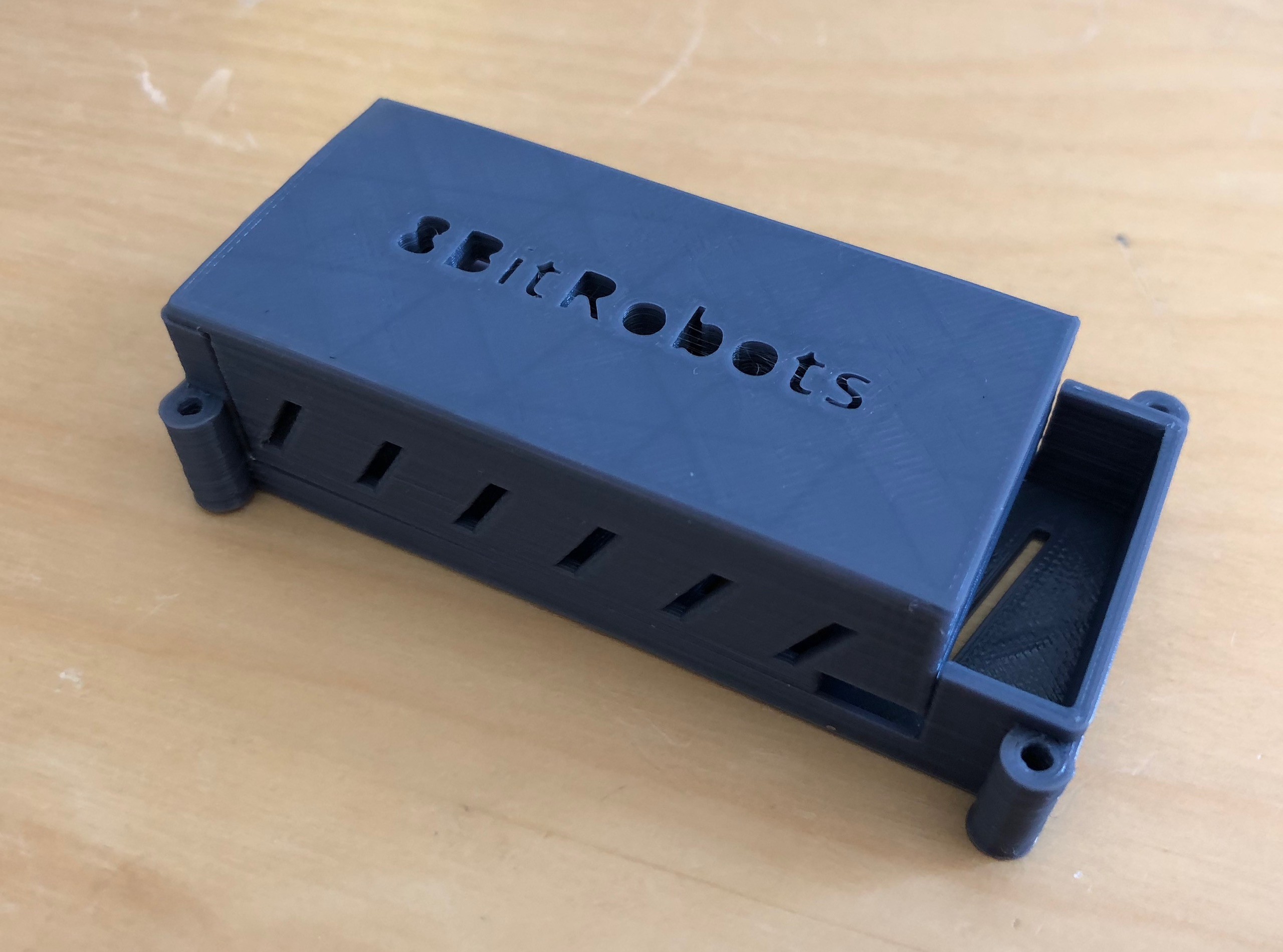
04/25/2018 at 20:54 • 0 commentsWith a 3D printed robot, you don't ... strictly speaking ... need a standard enclosure for the electronics. That said, it's useful to have a basic design as a starting point for customization.
![]() ---------- more ----------
---------- more ----------The Pi + RoBonnet fit snuggly into this box, has four M2 mounting points, and holes for all the Pi and Bonnet connectors.
![]()
-
And the robots?
04/25/2018 at 01:14 • 0 commentsThe final part of the 8BitRobots project are the robots. If you assemble all the different pieces in the stack, it'd be a bit of a shame if there was no actual robot at the end of it.
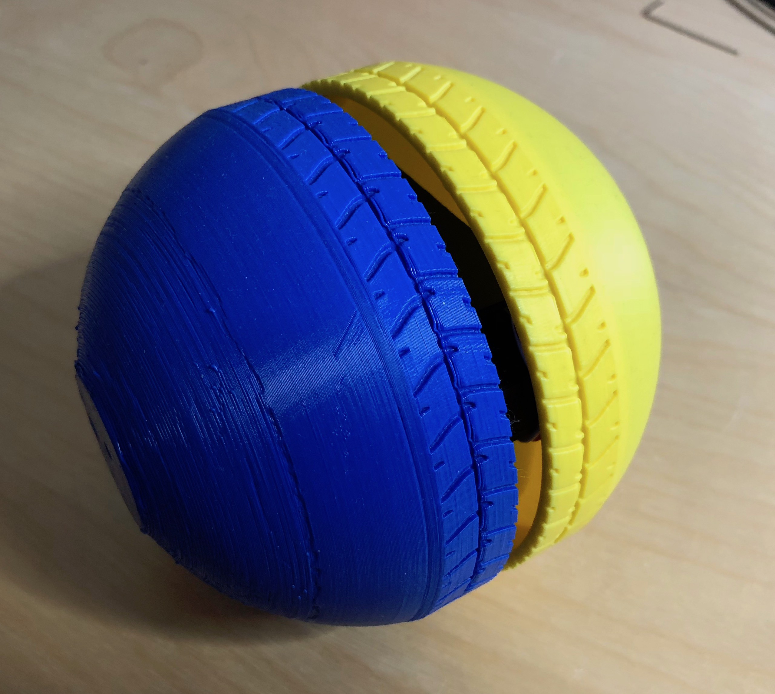
Over time I'll be releasing the 3D files for various printable robots so people can build and experiment in different ways. But for the first robot I've gone with something simple - a ball.
![]() ---------- more ----------
---------- more ----------The picture above shows the outer casing of a simple two wheeled robot; each half of the case forms one of the robot's wheels. The 8BitRobots module is hidden inside the ball, together with the motors and batteries. There are a few supporting printed parts and a couple of screws holding it together.
As you can see below, it's a zippy little thing.
But why blue and yellow? Two reasons; first, it's difficult to remember which way is forward if both sides are the same color, and second. CAL colors of course!
And ... finally ... why 8BitRobots when there's not an 8-bit processor in sight? Well, the 8-bit refers to the chunky, low-res, style of the robots; and I like the name.
-
Flash and Play: The Yocto Project
04/24/2018 at 22:27 • 0 commentsMost people who play with the Raspberry Pi download Raspbian as a starting point and then add whatever software they need on top. It's the sensible approach if you're comfortable playing with Linux. And while much of my development is done that way, I wanted something a little more "Flash and Play" for those who weren't super comfortable in Linux.
The Yocto Project (https://www.yoctoproject.org) is an open source project backed by lots of major vendors. It isn't a Linux distribution as such, but rather a way to build your own Linux distribution. And while I'm not interested in competing against Debian anytime soon, what I do want is an image that comes preconfigured for the 8BitRobots module.
I encourage you to go read about the Yocto Project and then take a look at my 8BitRobots meta layer (found here https://github.com/aanon4/meta-8bitrobots) which defines and configures all the extra bits you need to boot up an 8BitRobots node.
The image is flashed onto an SD card (I recommend the wonderful Etcher https://etcher.io for this), plugged into the Pi and booted up. The node appears as a wifi access point (with the name 8BitRobot-XXXX) which you connect to and go from there.
-
Phone as controller
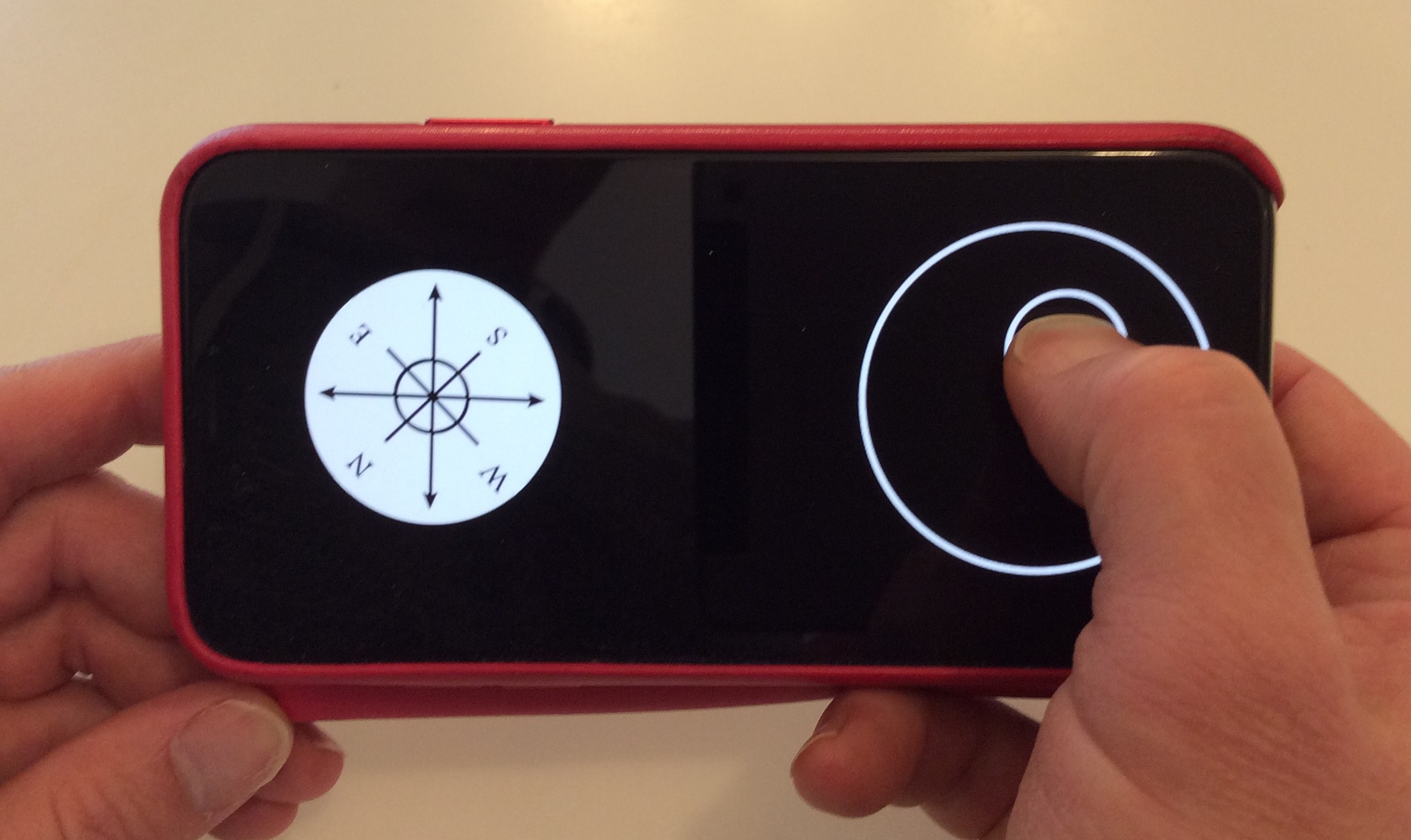
04/23/2018 at 05:22 • 0 commentsIf you own one of those cute Sphero toys, such as their R2D2 robot, then you're familiar with "phone as controller". There's a lot to like with this approach. I own various joysticks, gamepads, and RC controllers and they all have their place; but how many other people own them; or want to? Meanwhile we all own a phone with a touch screen.
The other big advantage of "phone as controller" is the versatile of the touch screen. Maybe the robot needs one joystick? Maybe two? Maybe a bunch of switches? Maybe specific information needs to be shown on the screen? How about the webcam video from the robot's "head"? The mobile phone is the idea places to put all of this, and arrange it in an appropriate, and fully customizable, way.
![]() ---------- more ----------
---------- more ----------Each 8BitRobots node runs a small web server. This is used for a variety of things, but here it servers the web pages to the phone providing the visual controls. And because it's a web page, it runs anywhere, and it runs Javascript just like the rest of the robot. In fact, the controller is just another node in the robot.
Ultimately, the controller will be fully configurable, with the ability to drag and drop the necessary visual elements onto the screen depending on the robot's needs. Each control will accessible through the Blockly programming language just like everything else in the robot.
For example, a joystick will publish events with its 'x,y' position. A Blockly program can take this information and use it to control the wheels of a robot. Different visual configuration with different controls will result in different blocks being available, and let the developer program their robots in new ways.
The current controller is very simple, consisting of a joystick and compass. The position of everything is fixed. Over the coming months I'm building out the visuals and a more flexible system.
-
Blockly
04/23/2018 at 05:06 • 0 commentsI'm not the first person to look over my children's shoulders while they're playing with Scratch and go ... hmmm ... could I use that for hardware? In fact, rummaging around on the Internet I found a few projects (including http://kinoma.com/ and https://www.parallax.com) that take this approach.
For 8BitRobots, I'm trying to use Blockly in a similar way, but under the hood doing things a little different.
![]() ---------- more ----------
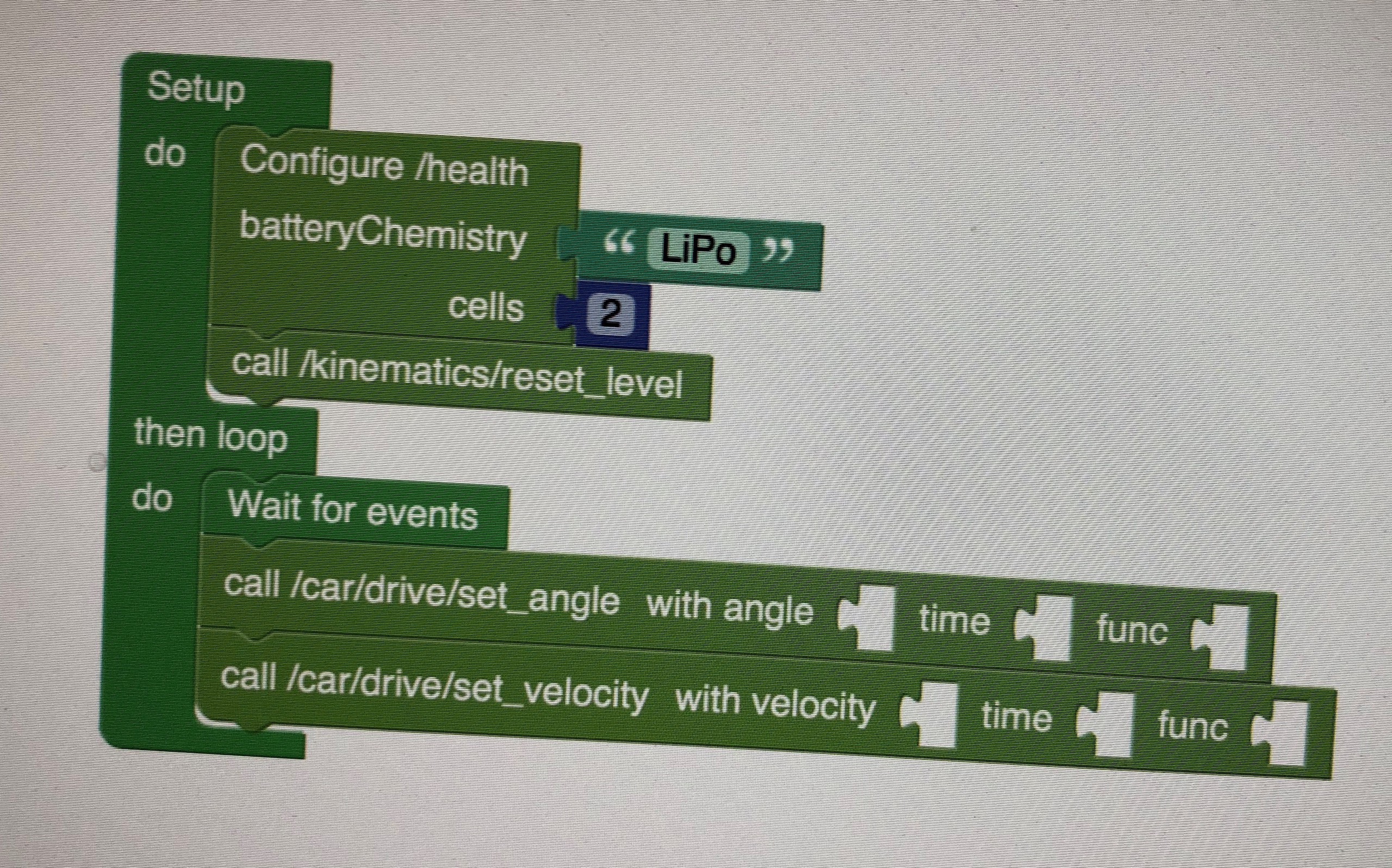
---------- more ----------Blockly for 8BitRobots is reflective; that is, it uses the 8BitRobots API to determine what the underlying hardware can support, and then creates the blocks necessary to interact with it. This means that as the hardware changes or new nodes are added, the Blockly programming interface will reflect these new hardware abilities automatically.
The Blockly part of the software platform is very new and very immature (you've been warned). I'm still struggling with what programming model is powerful but easy to use especially when getting started. The current model, seen above, looks very Arduino-like in approach. First it sets up the devices, then it loops over a program forever. But the underlying infrastructure is event based (the hardware and software sends topic updates) so perhaps this isn't the best?
Expect many changes as this evolves.
-
Software
04/22/2018 at 06:20 • 0 commentsThe software is written in Javascript running on NodeJS. I've always had a soft spot for Javascript, but here it was particularly appropriate as I have software running on hardware nodes and in web browsers. Javascript runs on both.
The actively developed iteration of the software can be found on GitHub at https://github.com/aanon4/8bitrobots
There are a few older versions of this software kicking about on my GitHub account (notably the version for my first ROV) and even this new version contains some legacy (and probably non-functional) parts. As this project evolves so will the software.
The 8BitRobots software is very ROS in its API style (though not in much else). Hardware and software makes itself available to the system as a set of services and topics. Services allow things to be controlled, topics provide information; and everything is named in a global namespace. The software runs under Linux on the Pi. Because I do most of the development on a Mac, it also runs there although the hardware is simulated or not supported.
The "config" directory in the main distribution contains some configuration setups for a few simple robots. Each named robot starts up a set to hardware and software services.
---------- more ----------There are a few tools to allow the robot state to be observed, and these can be found in the "utils" directory. The "8bit-list.js' tool is probably the easiest to use and simply discovers all the services and topics the robots supports.
If I were to run the robot software on a Mac:
sudo ./8bitrobot.js bot
You'd see something like the following:
bash$ sudo ./8bitrobot.js bot

*** Starting 8BitRobot: bot
Loading Globals.
Loading 8-Bit API.
Loading Server.
Loading 8-Bit Master.
Loading Console.
Loading I2C
Loading RaspberryPi I2C controllers.
Loading RaspberryPi board.
Loading GPIO
Loading RaspberryPi GPIO/PWM controllers.
Loading Motion Planner.
Loading SPI
Loading RaspberryPi SPI controllers.
Loading PCA9685 controllers.
Loading Config Manager
Loading State Manager.
 +/pwm-i2c/3/66/config
 +/pwm-i2c/3/66/4/current_pulse
 +/pwm-i2c/3/66/4/set_pulse
 +/pwm-i2c/3/66/4/wait_for_pulse
Loading DRV8833 H-Bridge controllers.
Loading BNO055 I2C/UART IMU sensors.
Loading BMP280 Environmental sensors.
Loading INA219 power monitors.
Loading GPIO Encoders.
 +/encoder/0/config
 +/encoder/1/config
Loading Kinematics.
 +/kinematics/config
Loading Environment.
Loading Health Monitor.
 +/health/config
Loading Networking.
Loading Tank Axle.
Loading 108mm wheels.
Loading FT90R continuous digital servos.
Loading Car.
Loading UI.
Starting /server/node.
 +/server/add_pages
Starting /master/node.
 +/list
Starting /console/node.
 +/console/log
Starting /imu/node.
 +/imu/orientation
 +/imu/acceleration
 +/imu/calibration
 +/imu/temperature
Starting /atmos/node.
 +/atmos/temperature
 +/atmos/pressure
Starting /power/node.
 +/power/status
Starting /encoder/0/node.
 +/encoder/0/rate
Starting /encoder/1/node.
 +/encoder/1/rate
Starting /kinematics/node.
 +/kinematics/orientation
 +/kinematics/acceleration
 +/kinematics/calibration
 +/kinematics/position
 +/kinematics/reset_level
Starting /environment/node.
 +/environment/external/temperature
 +/environment/external/pressure
 +/environment/external/humidity
Starting /health/node.
 +/health/compute
 +/health/battery
 +/health/status
Starting /networking/node.
 +/networking/config
Starting /car/drive/node.
 +/pwm-i2c/3/66/0/current_pulse
 +/pwm-i2c/3/66/0/set_pulse
 +/pwm-i2c/3/66/0/wait_for_pulse
 +/car/drive/wheel/left/current_velocity
 +/car/drive/wheel/left/set_velocity
 +/car/drive/wheel/left/wait_for_velocity
 +/pwm-i2c/3/66/7/current_pulse
 +/pwm-i2c/3/66/7/set_pulse
 +/pwm-i2c/3/66/7/wait_for_pulse
 +/car/drive/wheel/right/current_velocity
 +/car/drive/wheel/right/set_velocity
 +/car/drive/wheel/right/wait_for_velocity
 +/car/drive/current_angle
 +/car/drive/set_angle
 +/car/drive/wait_for_angle
 +/car/drive/current_velocity
 +/car/drive/set_velocity
 +/car/drive/wait_for_velocity
Starting /car/node.
 +/car/set_movement
 +/car/execute_gesture
 +/car/shutdown
Starting /ui/node.
Starting /activity/node.
You can then use the tools to query the robot:
bash$ ./8bit-list.js

Topics:
  /pwm-i2c/3/66/4/current_pulse
  /console/log
  /imu/orientation
  /imu/acceleration
  /imu/calibration
  /imu/temperature
  /atmos/temperature
  /atmos/pressure
  /power/status
  /encoder/0/rate
  /encoder/1/rate
  /kinematics/orientation
  /kinematics/acceleration
  /kinematics/calibration
  /kinematics/position
  /environment/external/temperature
  /environment/external/pressure
  /environment/external/humidity
  /health/compute
  /health/battery
  /health/status
  /pwm-i2c/3/66/0/current_pulse
  /car/drive/wheel/left/current_velocity
  /pwm-i2c/3/66/7/current_pulse
  /car/drive/wheel/right/current_velocity
  /car/drive/current_angle
  /car/drive/current_velocity
  /car/shutdown
Services:
  /pwm-i2c/3/66/config
  /pwm-i2c/3/66/4/set_pulse
  /pwm-i2c/3/66/4/wait_for_pulse
  /encoder/0/config
  /encoder/1/config
  /kinematics/config
  /health/config
  /server/add_pages
  /list
  /kinematics/reset_level
  /networking/config
  /pwm-i2c/3/66/0/set_pulse
  /pwm-i2c/3/66/0/wait_for_pulse
  /car/drive/wheel/left/set_velocity
  /car/drive/wheel/left/wait_for_velocity
  /pwm-i2c/3/66/7/set_pulse
  /pwm-i2c/3/66/7/wait_for_pulse
  /car/drive/wheel/right/set_velocity
  /car/drive/wheel/right/wait_for_velocity
  /car/drive/set_angle
  /car/drive/wait_for_angle
  /car/drive/set_velocity
  /car/drive/wait_for_velocity
  /car/set_movement
  /car/execute_gesture
Want to monitor the compute health of the system, just use the 8bit-monitor.js command:
bash$ ./8bit-monitor.js /health/compute {"cpu%":1.2,"mem%":82.50692915301106} {"cpu%":1.6,"mem%":79.3459231616141} {"cpu%":2.1,"mem%":80.18690310067595} .... -
RoBonnet v0.1
04/22/2018 at 05:59 • 0 commentsThe core to my robots is PWM. This is true for the robot arm (servos), the robot car (ESCs), or the ROV (more ESCs). The Raspberry Pi only has a single PWM output and while you can use software to create a few more, early experiments with this method quickly showed its limitations. My first PWM control board was from Adafruit a long time ago, and I've based all my robot controls on the same solid PCA9685 which provides 16 PWM outputs.
![]() ---------- more ----------
---------- more ----------The first version of the RoBonnet (shown above) was a simple test bed for this chip and the basic board form factor (the IMU test to the left of the PCA chip failed - guess I screwed that up). This version brings out 8 of the 16 PWM signals. The Pi plugged face down into the 40-pin connector at the bottom. To the left you see the power input and a pre-purchased power board (from Pololu.com).
Although you can't tell from this picture, the board is longer than the Pi so the PWM pins are accessible, but this version was just a little too short so it partially obstructed some of these pins. I had to make it 2mm longer because, apparently, I can't measure stuff properly.
The power connector on the right was choses to accept the standard plug you find on a 2S LiPo battery (thank you Beagleboard Blue for that idea). The converter turns that into 5V which is used to power the Pi as well as everything else. The final goal is to provide 3A at 5V to the node and attached hardware.
The boards were prototyped using DirtyPCB.com which I've found to be a fantastic, quick turnaround service. Assuming you avoid the Chinese New Year (I didn't) you can go from submission to board-in-hand in a week.
8BitRobots Module
A common hardware, software and 3D printed module to enable fun, educational robots anyone can print and program.