During the recent flooding associated with Hurricane Harvey a common concern among homeowners trapped in their homes by overflowing bayous and flooded streets was the desire to disconnect individual electric circuits and/or home service as waters begin to threaten homes and their occupants. The dangers of live electrical service in a flooded home were unfortunately highlighted by at least one documented electrocution. This incident, along with the stories of fellow Houstonians standing in heavy rains and/or flood waters as they attempted to manually disconnect electrical circuits inspired this project.
Developed by a team of student engineers based in Houston, the Flood Fault Circuit Interrupter represents the opportunity to address a problem which is both universal as well as personal. Hurricane Harvey was a particularly significant event for Houston. However, even in recent memory Houston has suffered significant flooding, such as during the 2016 tax day floods. Other regions in the Gulf Coast and Caribbean have also suffered through historic hurricanes, with just the past season including infamous storms like Irma and Maria. Looking further out, named storms such as Sandy on the east coast as well as recent devastating rains in Hawaii demonstrate the wide reach of flooding-related challenges. One element which is unfortunately present in so many of these events is the story shared by one of our own team members (whose Harvey-flooded home is pictured in our project page): the challenges and dangers presented by sheltering in a home inundated by flood waters.
Currently residential electrical services will, in ideal circumstances, employ passive design techniques to minimize the impact of flooding. These include design choices around the location of service disconnects all the way to how wiring is routed to outlets within the home. Additionally, active measures such as Ground Fault Interrupters and Arc Fault Interrupters may protect only targeted areas of the home as specified in the National Electric Code.
Ultimately, proper disconnection of electrical service can present a significant danger for the end-user in flooding conditions as it requires the operator to approach a service panel (which may be located outside) during heavy rains or, even worse, while standing in floodwaters.
The Solution
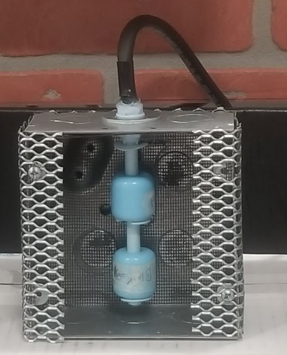
The intention of the Flood Fault Circuit Interrupter is to layer upon the aforementioned protections an active monitoring system which would respond to flooding measured around a target location and perform an automated disconnect of electrical service. In addition, the system could be enhanced to allow for operator-initiated activation of the disconnect.
 Jon
Jon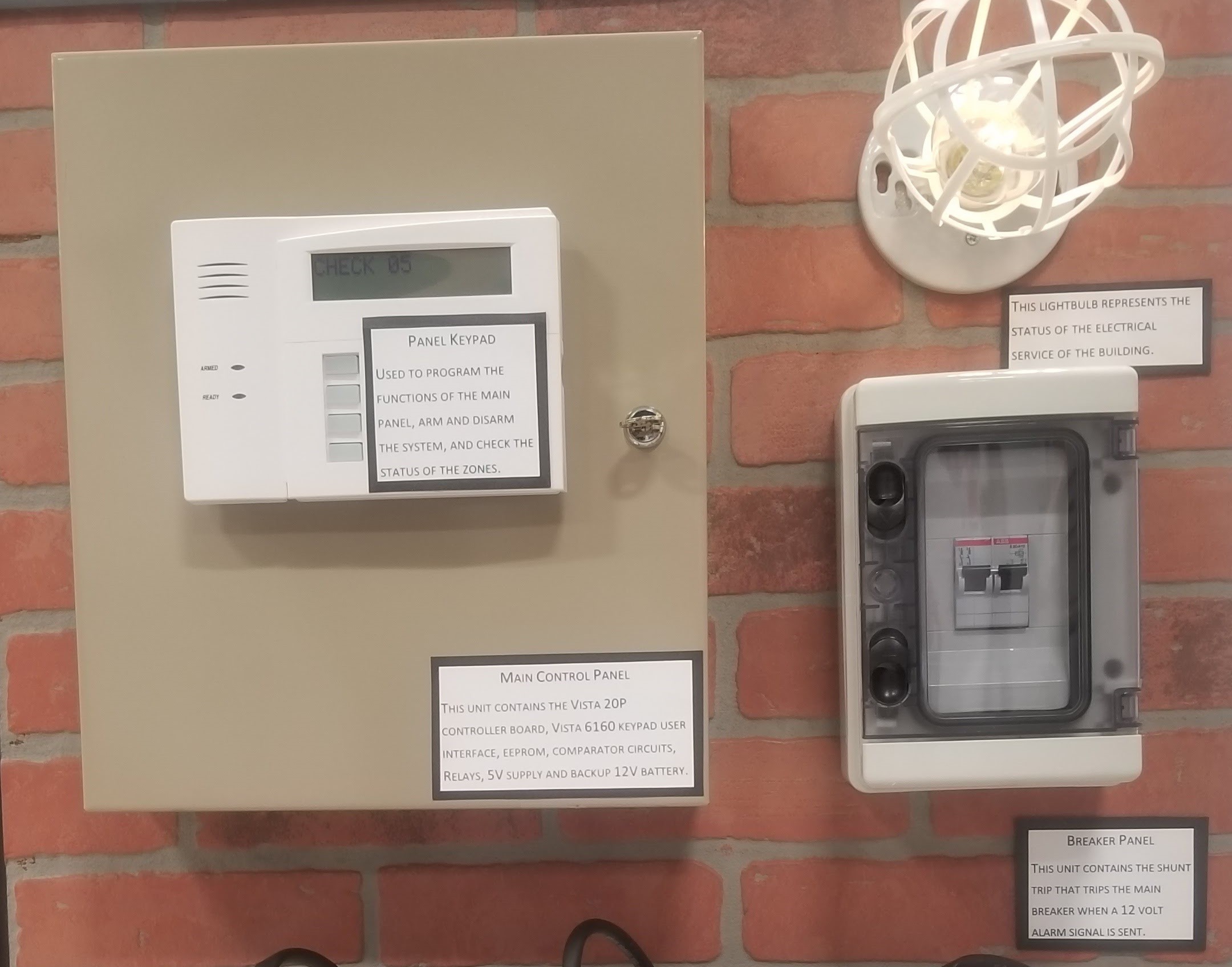

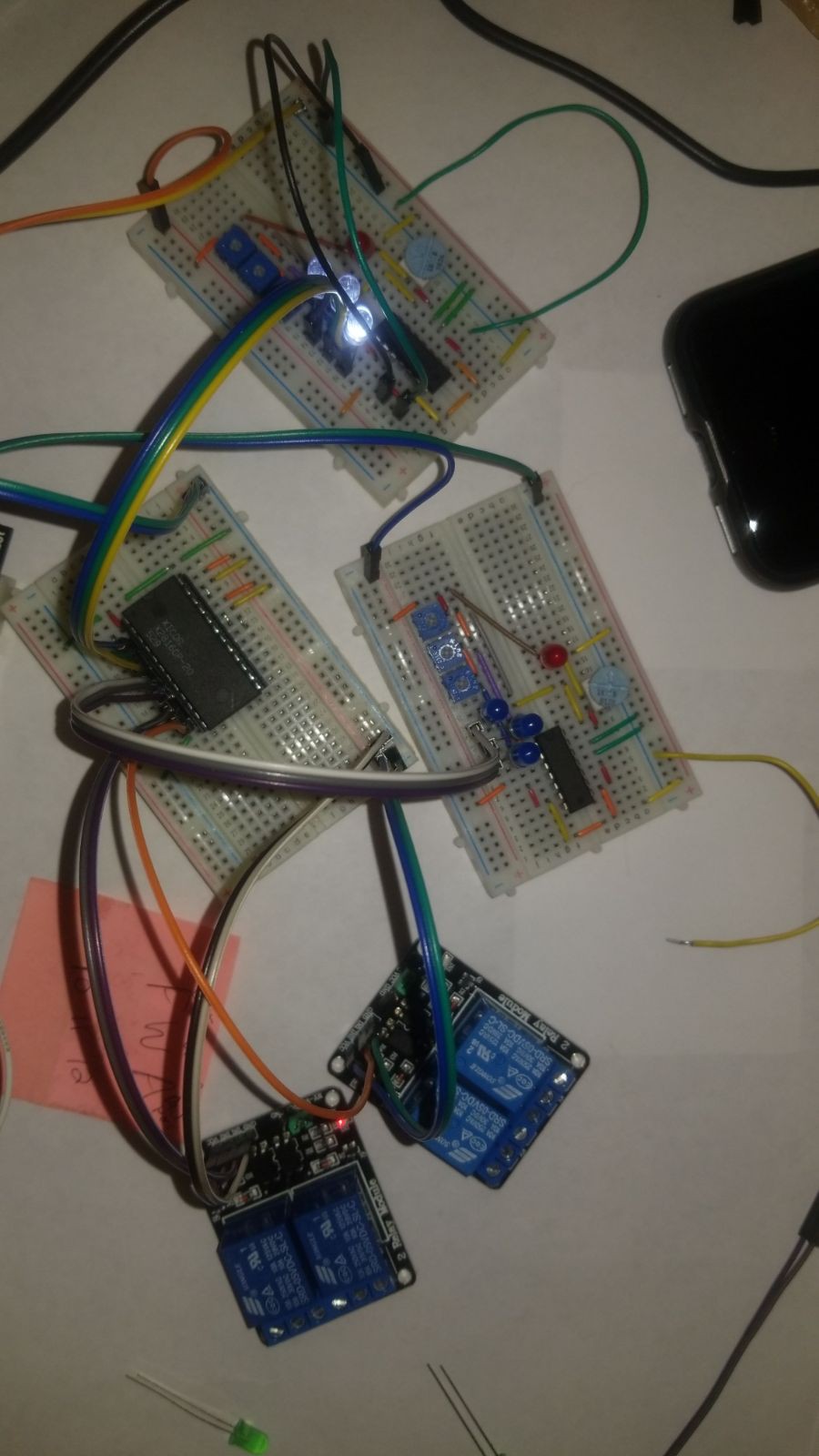
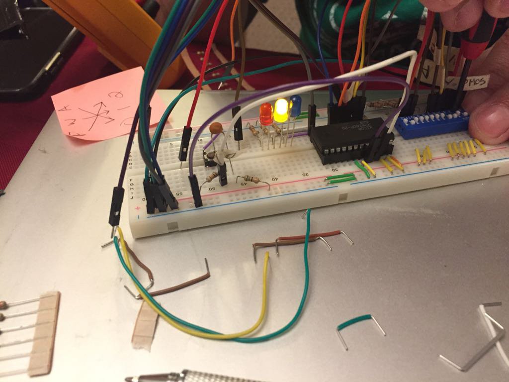
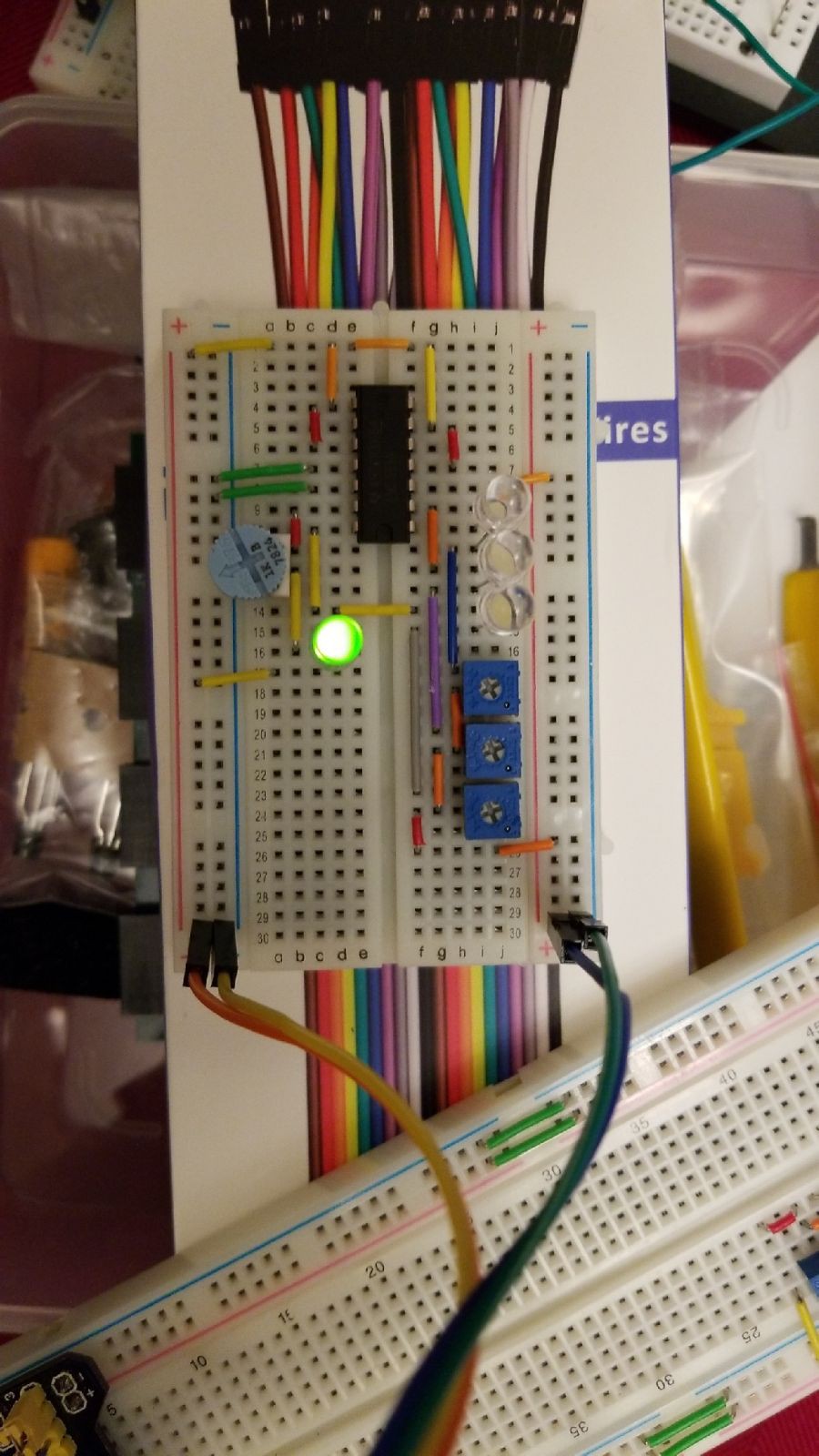


That's a great idea for another project log. Short version: if you look in the block diagram model, the EEPROM is the Logic element of the system and determines when FAULT, WARN, and ALARM states are communicated to the control panel.
The EEPROM stores the appropriate output response to each of the 64 possible combinations of input switch states (recall that there are six switches total). The output side of the EEPROM connects back to three (3) relays which are then connected to three security panel zones dedicated for each state/response. FAULT and WARN trigger an audible alarm only on the control panel in addition to a visual warning (the panel will display FAULT or WARN). ALARM includes the audible and visual alarm and also sends a trigger signal to the shunt trip breaker pulling the breaker to OFF.
The switches are connected to the security control panel directly but security control panels have relatively limited logic functionality. This will likely need to be another dedicated project entry so that I can see if any Hackaday contributors have additional insights. There are, however, other advantages provided by the integration of the security panel as the controller (around power management and line fault monitoring).
My next project entry will be about a security element which is my primary target for integration (a Zone Expander). However, I'll try to follow up with two entries. One will be on the Karnaugh maps / lookup tables which document the logic rules we used. From there I'll detail out the EEPROM as implemented. Please feel free to reply back with any other documentation notes I could add which you think might be helpful?