-
System Interface and Sub-Panel
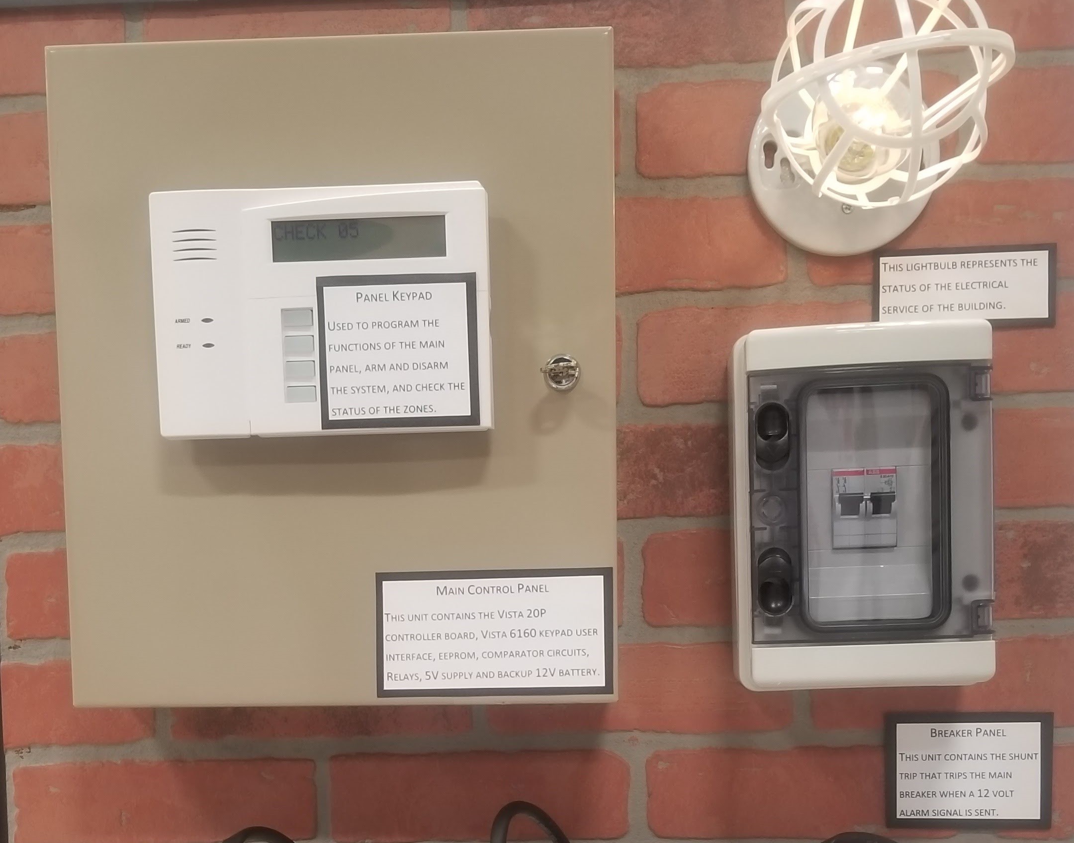
04/23/2018 at 09:14 • 0 commentsThe security panel keypad acts as the primary system interface. Audio alerts are available via the keypad and statuses are displayed both for individual switches as well as for the warning, fault, and flooding outputs designated for the FFCI system.
Any individual switch which is either activated or faulted (wire is open circuit) will be identified using a visual alert. A warning status is communicated with a visual alert in addition to an audio alarm when any three (3) of six (6) float switches are activated. This does not remove the system from power. Additionally, a special fault status is defined when the three topmost float switches are activated but the three bottom float switches remain inactive. Lastly, when any four (4) or more of the six (6) total switches are activated the flooding status will be made active which includes both audiovisual alerts as well as an alarm communication to the shunt trip which disconnects the circuit demonstrated by the light bulb.

-
Float Switch Detail
04/23/2018 at 09:05 • 0 commentsHere is a detail view of the mechanical float switches inside an enclosure. Note how fabric mesh has been applied inside the enclosure to provide basic filtering of small particulates. A heavier gauge mesh has been applied outside the enclosure to provide physical protection. Although the enclosure is designed from multiple metal pieces, the final production version would likely be much simpler to reduce costs.

-
First Complete Mock-Up
04/23/2018 at 09:01 • 0 comments -
Power Supply on the Cheap
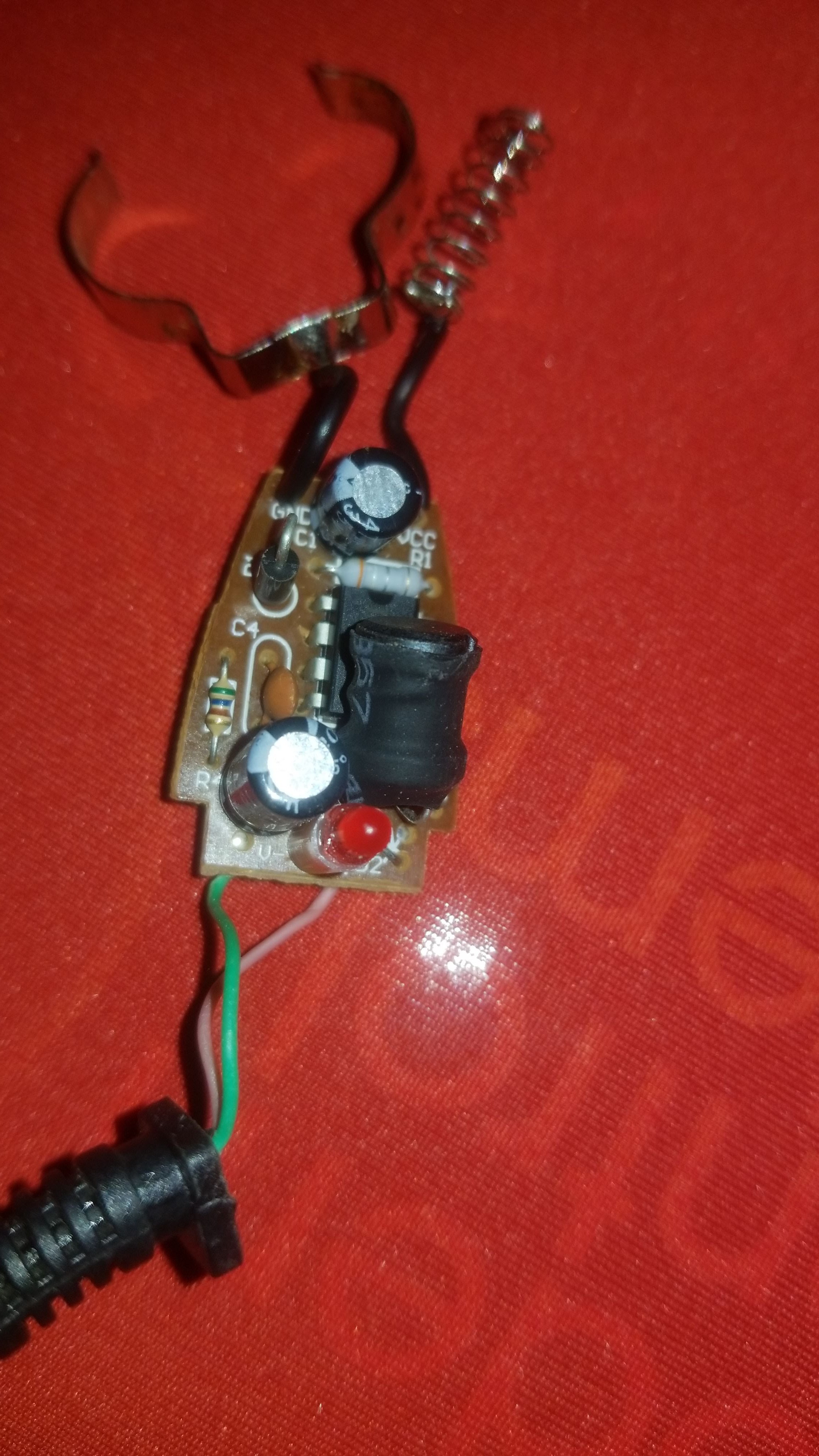
04/23/2018 at 08:58 • 0 commentsOur first power supply for the 5V circuits was a highly efficient switched mode power supply evaluation unit based upon a Texas Instruments chip.
However, a short-circuit during testing damaged that initial unit and an interim replacement was selected. Given the very low current draw of our 5V components, we selected a power supply recovered from a car charger based upon the MC34063 chip.

-
Mocking up EEPROM, Comparator, and Relays
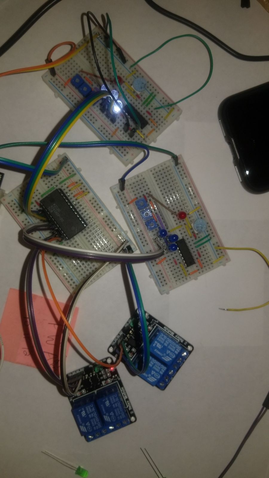
04/23/2018 at 08:50 • 0 commentsThe input comparator circuits, EEPROM, and output relays were connected together and tested prior to interfacing them with the security panel.
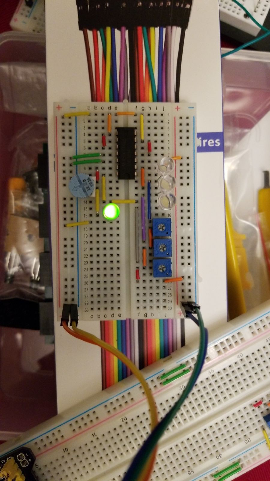
Note the later revision of the comparator circuit. Here the power LED is also generating the reference voltage for the other comparator inputs. Potentiometers are used to fine-tune the voltage at the indicator LEDs to a range appropriate for the LEDs selected (here blue & white 3.3V forward voltage LEDs).
The test leads wired to ground on the topmost comparator are simply meant to represent a zero (0) voltage closed switch input.

-
Programming the EEPROM
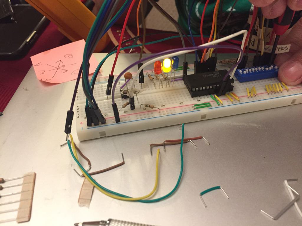
04/23/2018 at 08:37 • 0 commentsThe EEPROM was manually programmed using a basic breadboard circuit. This system enabled simple programming, but might be impractical given enough inputs. As built, the system supports six (6) switch inputs with three (3) outputs. This required the programming of 64 entries. The number of entries is simply a function of two to the power of the number of inputs (2^6 = 64).
LEDs were used to provide a visual indicator of the output levels being programmed. DIP switches were used to select appropriate address values. An RC circuit and momentary switch were used to achieve the necessary specifications required by the EEPROM datasheet to communicate a write mode.

-
Comparator Circuit (1st Revision)
04/23/2018 at 08:24 • 0 commentsA comparator circuit was mocked up to bridge the voltages on the Vista 20p security panel associated with each switch zone. Each comparator was assigned three (3) of the total six (6) switch zone inputs. The outputs of the comparators were each wired to an LED and comparator to provide both a reference voltage value and visual status indicator. The fourth open comparator input on each chip was wired to power an always ON LED.
The comparator circuit was required because the selected security panel voltages could range from as low as zero (0) volts to twelve volts. Switches were configured using the security system standard of normally open with End of Line (EOL) resistor. In normally open status the circuit voltage would be five (5) volts DC through the specified EOL resistor (2k ohms). A short circuit / closed switch would drive a zero (0) volts level. Open circuit voltage was 12 volts, which would only be present under fault conditions such as cut wires.
However, as any range outside of 5V could damage the selected EEPROM inputs the comparator was used to compare the voltage reading at the high side on the security panel to a reference voltage (3.3V was selected as an arbitrary value sufficiently between zero and 5).

Flood Fault Circuit Interrupter
Automate the local disconnection of electrical services during a flood. Enhance the safety of existing residential and commercial systems.
 Jon
Jon