Close
0%
0%

2D actuator move micro robot in X/Y 2D space

Less than 10$ educational platform with micro magnetic robot (mBot),
only 6 GPIO to move in unlimited X/Y 2D space

Similar projects worth following
Great for physical education for languages like Karel and make
SKOBAN game or solve LEGO labyrinth.

My project not violating SRI international patent
(maybe, I am not patent expert)

There is differences:

- I am using another moving track configutation
- Control is 3-phase unipolar against 4-phase bipolar
- My manipulator (mBot) use 4 magnets and not levitating
- For move in one dimension I need only 3x Mosfets connected to any MCU
(Arduino Atmega328, Stm32, MSP430, ESP XXXX)
- 6 GPIO to move in X/Y 2D space
- Moving board can be produced in any fab, it is just only PCB board 8/8mil
- IT IS CHEAP

Hackaday article about this project https://hackaday.com/2018/05/22/smiling-robot-moves-without-wires/

2019 - touch control

Button control

This prototype is designed with atmega328 but I thinking about SAMD21
( 3 ways for programming Arduino, Circuitpython, Makerscode)

At first sight it is very simple but I have doubt, there is absolute no other videos, no similar projects
why? where is problem?
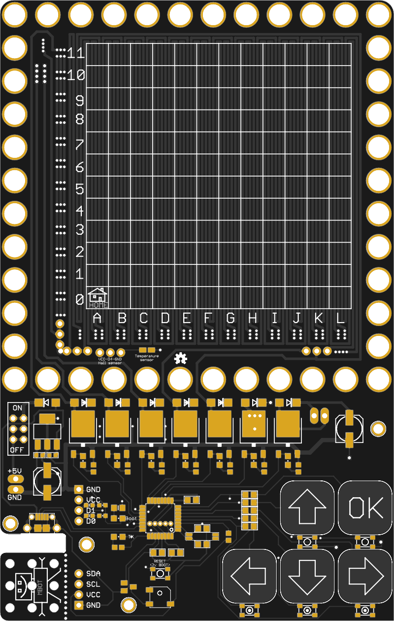
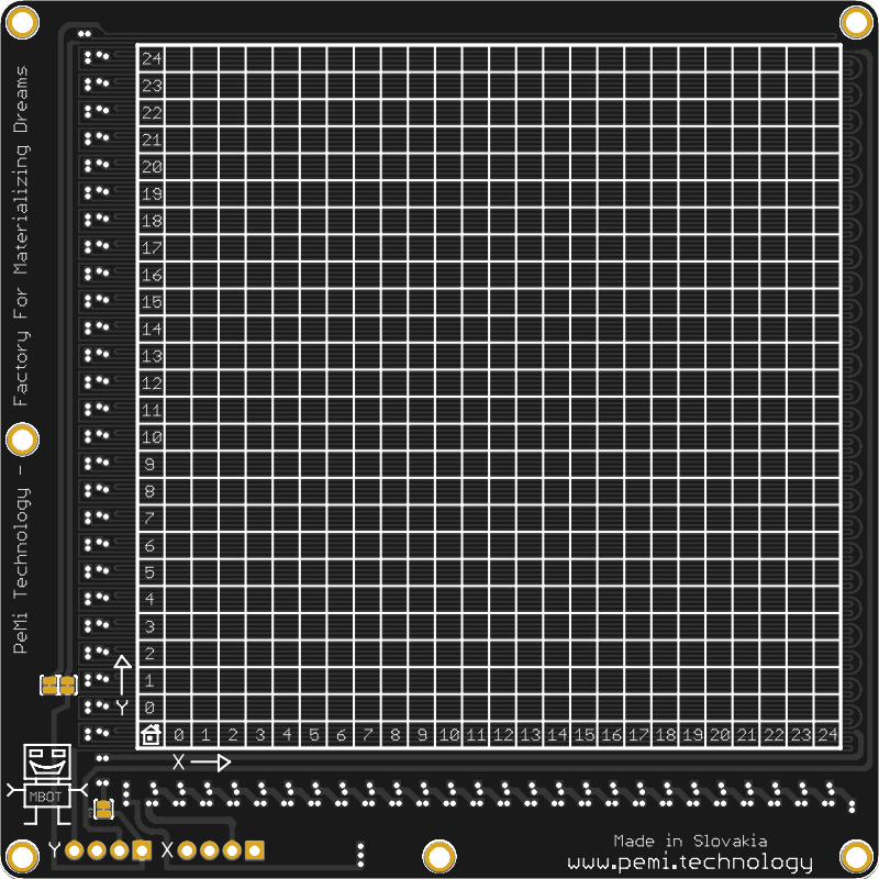
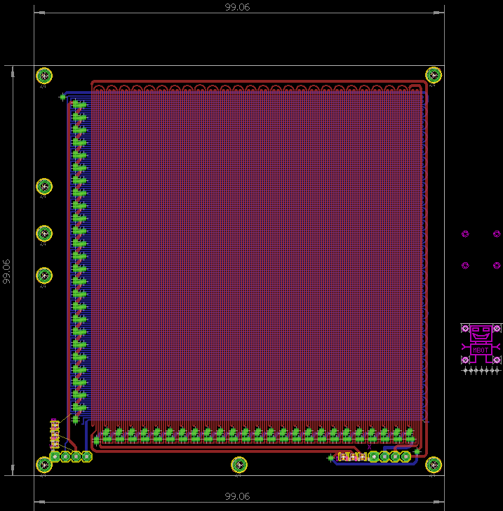
Board is designed as 3 phase linear coils switched with mosfets


What next? 

TO DO:

- NFC comunication with bot ?

- feedback, where is wall, object

- manipulation with objects, make gripper?

- home position sensor

- rotation corner

I am very impressed with this video

MAGNEBOT2.sch

experiment with rotating corner

sch - 1.15 MB - 04/23/2018 at 18:57

Download

MAGNEBOT2.BRD

experiment with rotating corner

brd - 138.60 kB - 04/23/2018 at 18:57

Download

MAGNEBOTd21.sch

sch - 1.14 MB - 04/23/2018 at 18:56

Download

MAGNEBOTd21.BRD

brd - 122.71 kB - 04/23/2018 at 18:56

Download

MAGNEBOT328RTMX.sch

sch - 1.12 MB - 04/23/2018 at 18:55

Download

View all 6 files

  • 1 × PCB with moving tracks Main part and very easy replicate in any PCB fab
  • 4 × 1mm or 2mm magnet for robot Untested now, magnets are on way, tested with 5mm and result is good
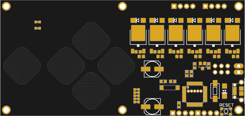
  • 1 × Controller board not finished now but it is only simple 6 MOSFETS connected to arduino

View all 9 project logs

  • 1
    PCB

    Almost all magic is in pcb structure, buy/order board

  • 2
    Componets

    Solder all components on to PCB

  • 3
    SW

    upload test code

View all 5 instructions

Enjoy this project?

Share

Discussions

1903152960 wrote 04/03/2023 at 07:31 point

how to solve the heat problem

  Are you sure? yes | no

rainer wrote 03/06/2023 at 10:01 point

Great project, have many ideas to use it on my model railways.

Is the code for the 328 also available?

  Are you sure? yes | no

Tom wrote 03/20/2021 at 10:12 point

Fantastic project, do you have any update?

  Are you sure? yes | no

malcolm mckean wrote 02/01/2021 at 22:52 point

Hi, wondering if it's possible for this to be done on a larger scale, for example would a 30 x 30 cm grid be possible?

  Are you sure? yes | no

Julio Cesar Zebadua wrote 06/02/2020 at 21:45 point

Excellent project. Is there the option to obtain the code to build my own?

  Are you sure? yes | no

Trevor Johansen Aase wrote 05/16/2019 at 17:56 point

Any ideas on how to implement multiple zones? In the SRI video is kind of looks like they are set up in individual strips or with seperate "parking zones" but in the first example in the video with two moving at once this is not the case.

It also appears they are using copper or foil tape over the PCB, I don't see a lot of the magical diamagnetic graphite (must be crazy expensive in those sizes), I would think it would even out the fields. Have you tried to see what the copper tape would do?

Have you tried the zig-zag trace pattern? It'is mentioned that its an easier control mechanism. Have you tried PWM on the FETs to try out speed control?

  Are you sure? yes | no

bobricius wrote 05/19/2019 at 20:48 point

You can read SRI patent, it is public. 0.6mm board is to fat, I want try on flex or 0.2mm

I am working on may projects now I have untested new boards. microstepping not working... only half step. I using 20-30PWM to KEEP TRACK feature ... (etc ... when moving on X, enegizing Y lines to 20% to better movement stability)

  Are you sure? yes | no

Bryan wrote 05/10/2019 at 22:50 point

Sooooo many possibilities here! At the simpler, fun level, some games could be made, like the old classic, Pong. With LEDs on the edge of each side for "paddles". Each side could have a left and right  button, to move the LED paddle. Would probably need a shift register to reduce the amount of outputs needed, and something to sense if the paddle got there in time to hit the "ball". But the possibilities are enormous for this. Awesome job!

  Are you sure? yes | no

Meek The Geek wrote 05/09/2019 at 21:08 point

I would like to see this used in a braille display

  Are you sure? yes | no

vlk wrote 03/26/2019 at 09:58 point

you can make a sokoban game!

  Are you sure? yes | no

miro2424 wrote 06/27/2018 at 12:57 point

Hey, when the new PCB board is coming? Waiting to see your new video with the touch controller.

  Are you sure? yes | no

bobricius wrote 06/27/2018 at 13:21 point

I am exhausted with other projects, 1-3 weeks. I need redesign moving matrix.

  Are you sure? yes | no

hyperzap wrote 05/21/2018 at 03:53 point

This is awesome!! Any chance you can render the schematic as an image for KiCad peeps like me :) I'm also a little confused as to how the matrix of fields works. From what I can tell, you turn on a bunch of lines at once, but the bot is most attracted to the closest one?

Also, what are your trace widths and separation for the coils :)

<3

  Are you sure? yes | no

ken.do wrote 05/10/2018 at 18:58 point

Great project! Very cool

  Are you sure? yes | no

Ed0 wrote 05/06/2018 at 15:46 point

I also tried replicating the SRI patent but had problems with the magnets.  In retrospect I should actually measure them and make sure they are strong enough for it to work.

Also see http://spritesmods.com/?art=magnmicrobots&page=2

  Are you sure? yes | no

miro2424 wrote 05/05/2018 at 22:05 point

Nice! Instead of making a ouija board, I would suggest to make a watch based on this technology. 

  Are you sure? yes | no

bobricius wrote 05/05/2018 at 22:23 point

It is my first non watch project :)

  Are you sure? yes | no

ken.do wrote 05/10/2018 at 18:58 point

Can I get this... as a watch? :P

  Are you sure? yes | no

Jarrett wrote 05/04/2018 at 22:13 point

Very cool. What kind of voltage/currents are you using for the electromagnets?

  Are you sure? yes | no

bobricius wrote 05/04/2018 at 22:23 point

I am sorry, I have broken lab ampere-meter. Standard 5V 2A phone charger.

USB tester show consumption 2.3A 9W ... voltage drop to 4V On move only.

  Are you sure? yes | no

danjovic wrote 05/03/2018 at 23:16 point

Hmm... now that I notice that it resembles an ouija board. Have you consider doing a halloween version?

  Are you sure? yes | no

bobricius wrote 05/04/2018 at 05:45 point

:D or Jumanji 3

  Are you sure? yes | no

bobricius wrote 05/02/2018 at 19:14 point

on video I directly connecting 5V adapter.

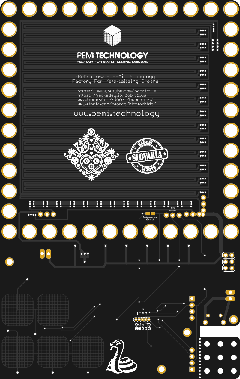
I repeat on board 3 coils, simple loops only (you can check in galery), if you switch 1-2-3 repeatedly magnet go forward, otherwise 3-2-1 magnet go back. on board is on top layer y coils and bottom is for x. my first idea was to use coil matrix 8x8 colis but when I look detail on SRI video the use only simple lines and to board is connected only 3-4 wires. I tested on one my old board with long track directly powered can move magnet. In theory you can with only 6 signals move robot on unlimited 2D space.

I am waiting for mosfets to control it with mcu and smaller magnets.

  Are you sure? yes | no

Mike Szczys wrote 05/02/2018 at 18:31 point

In the demo video, what are you using to actuate the movements? Is each swipe just sequencing which order the coils are energized?

Very cool proof of concept!

  Are you sure? yes | no

Similar Projects

Does this project spark your interest?

Become a member to follow this project and never miss any updates