TTN
TTN-
Careful observations..
04/05/2015 at 20:20 • 0 commentsAfter the following video was shot, I did some careful stopwatch work and found is actually running at approximately 3.5 times than reported. This means that in the video it is actually running at 56mm/s perimeters and infill at 140mm/s at 1400mm/s^2 acceleration.
This is because the firmware calculates the speed at the motors, rather than at the end effector. The moves of the print head a proccessed in segments per second. The arduino struggles to calculate more than 40 segments per second due to the math thats required to run this. I plan on moving from Marlin firmware to Repetier firmware as Repetier is written with speed and efficiency in mind. Hopefully this will allow for more segments per second and so more precise movements.
At speeds over ~50mm/s actual, backlash becomes visible. I think I've identified where it is coming from mainly:- Frame flex (lifting the printer onto another bench throws the bed off from level)
- Flex in the stepper pulley motor shafts, as the pulleys are mounted too far from the motors.
- Flex in the wood chipboard mounting plate
- The upperarms are quiet rigid as are the pulley mounts. I think fixing the above mentioned issues will help a lot.
-
Faster Firmware
01/03/2015 at 11:25 • 2 commentsA follow up on my previous project log:
This firmware hasn't become any faster. The next thing to try is adding inverse kinematics to a firmware that has had performance in mind since its beginnings.
Teacup and Repetier firmware are both using long ints and ints for all calculations instead of floats, as the avr cpu doesn't have the hardware for doing float calculations so it is much slower. For example, 10,000 float operations of multiplication take 212ms, where as to do them as int's takes only 127ms, much faster.
I initially wanted to use Teacup firmware, but there is no delta printer support, making the addition of inverse kinematics a lot harder, so, for now I'll see how much faster it will go on Repetier.
It shouldn't be very difficult to integrate the inverse kinematics function into Repetier, but I'm a c++ noob and have been busier lately, so this may be put on the backburner for a while.
To be continued..
-
New pulley wheel
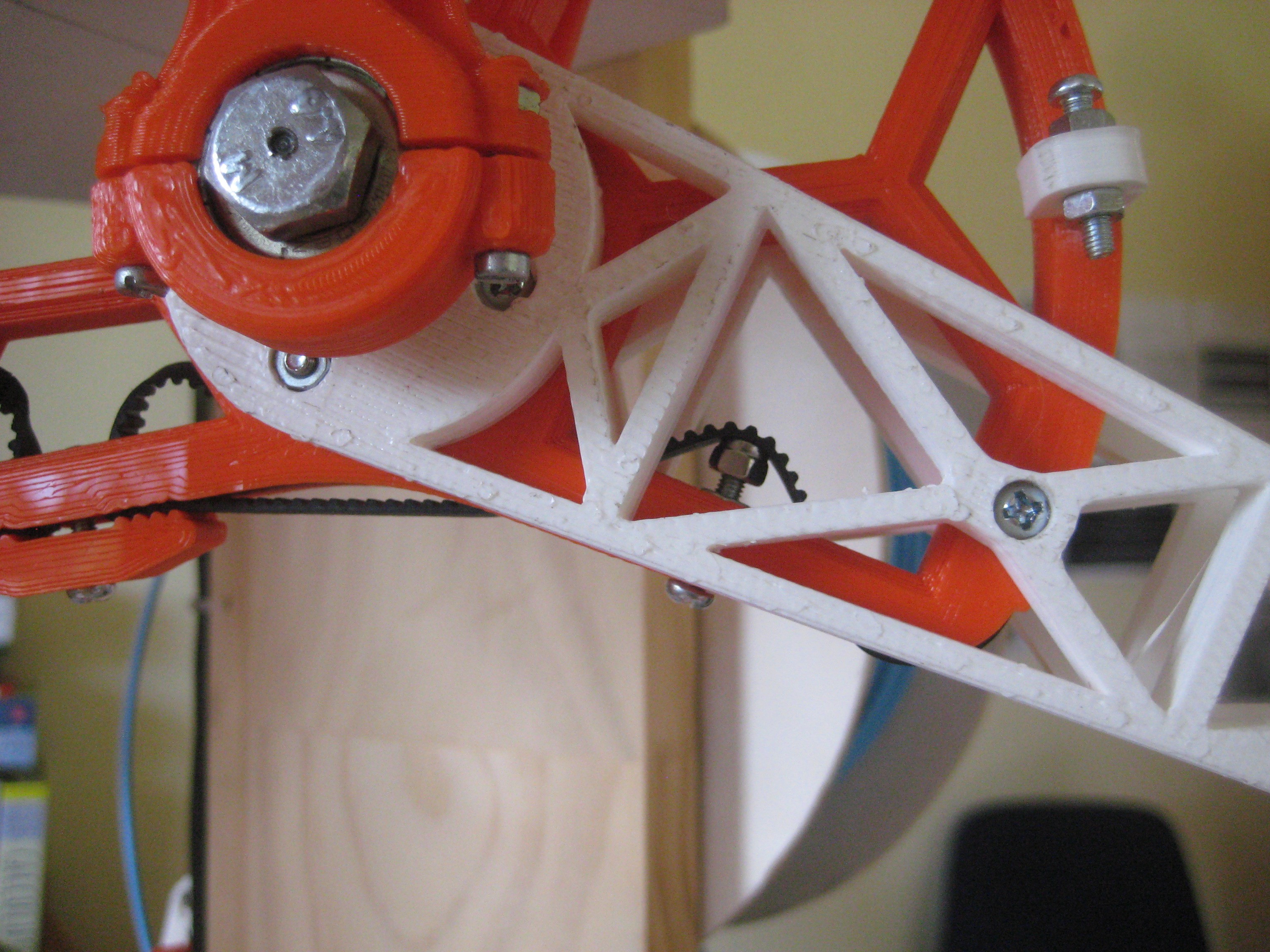
12/20/2014 at 19:52 • 0 commentsThe original upper pulley wheels where fine, but it was difficult to tension the belt. So I redesigned them:
![]()
The new pulley design has a piece in the lower right section for tightening the belt by screwing in the screw:
![]()
The upperarms are also less prone to catching on the lower arms when homing from varying positions.
-
Arc tangent lookup function
12/20/2014 at 19:46 • 0 commentsAfter struggling with C code for a while I've managed to make a function which calculates the arctangent value by means of a lookup table, which is much faster than recalculating the arctangent value each time it is needed. But is it actually faster than the arctan in the Arduino library?
//===================================================
//==== lookup table for arctan (testing 123..) ======
//===================================================
float scale_float = 10.0; // used to increase number of points in LUT_atan array
const int scale_int = 10;

const int w = 20 * scale_int;
float LUT_atan_array[w]; // should be 20*scale, but am struggling with the syntax


void make_atan_array() {
  for (int i = 0; i < (20 * scale_int+1); i++)
  {
    LUT_atan_array[i] = atan(int(i) / scale_float);
  }
}

float LUT_atan(float rads_in) {
  float num = rads_in * scale_float;
  int is_negative;
  if (num < 0)
  {
    is_negative = 1;
    num = num - 2*num;
  }
  else
  {
    is_negative = 0;
  }

  // pick a point in the array below num and above num
  int X0 = int(num);
  int X1 = X0 + 1;
  float Y0 = LUT_atan_array[X0];
  float Y1 = LUT_atan_array[X1];

  // linearly interpolate between points in array
  float slope = (Y1 - Y0);
  float result = Y0 + (num - X0) * slope;

  if (is_negative == 1) // if input was negative, make the array output negative
  {
  result = result - 2 * result;
  return result;
  }
  else
  {
  return result;
  }
}
Writing this in python was easy, doing it in C: not so easy. I found a way to run it against the actual arctangent function and print the values comparing them to serial. It is accurate to 3 decimal places. Timing how long it took to do 10,000 iterations (approximately 130milli seconds on an Arduino Mega 2560) showed that my function was about two or three miliseconds slower per 10,000 iterations than the atan function in the Arduino library, which is dissapointing. This means the Arduino math library is probably already using a similar lookup table method.Oh well. Now I know more about C++ and lookup tables :)
-
Firmware
12/13/2014 at 05:12 • 0 commentsSince the Icepick-delta is a true non linear deltabot, it requires some math to move it. It turns out this has done this before (yay!). A big thank you to mzavatsky for writing the inverse kinematics code and bigdaveakers for making it so much easier to incorporate into marlin.
Replacing the delta functions in marlin_main.cpp and adding defines to configuration.h and we have results!
#ifdef DELTA

float f = BASE_SIDE;
float e = END_EFFECTOR_SIDE;
float rf = DELTA_ARM_LENGTH;
float re = DELTA_DIAGONAL_ROD;

const float sin120 = DELTA_SIN120;
const float cos120 = DELTA_COS120;

float x0;
float y0;
float z0;

// the function is called with like so at another point for the M665 gcode command: recalc_delta_settings(delta_radius, delta_diagonal_rod);
// for initial testing, this will be ignored

int delta_calcAngleYZ(float x0, float y0, float z0, float& theta)
{
float y1 = -0.5 * 0.57735 * f; // f/2 * tan 30
y0 -= 0.5 * 0.57735 * e; // shift center to edge
// z = a + b*y <-- what is this for?
float a = (x0*x0 + y0*y0 + z0*z0 +rf*rf - re*re - y1*y1)/(2*z0);
float b = (y1-y0)/z0;

// discriminant
float d = -(a+b*y1)*(a+b*y1)+rf*(b*b*rf+rf);

if (d < 0) return -1; // non-existing point

float yj = (y1 - a*b - sqrt(d))/(b*b + 1); // choosing outer point
float zj = a + b*yj;

theta = atan(-zj/(y1 - yj))*(180/DELTA_PI) + ((yj>y1)?180.0:0.0);

return 0;
}


void calculate_delta(float cartesian[3])
{
// inverse kinematics: (x0, y0, z0) -> (theta1, theta2, theta3)
// returned status: 0=OK, -1=non-existing position

float theta1 = 0.0;
float theta2 = 0.0;
float theta3 = 0.0;

x0 = cartesian[X_AXIS];
y0 = cartesian[Y_AXIS];
z0 = cartesian[Z_AXIS] - DELTA_HOME_POS;

int status = delta_calcAngleYZ(x0, y0, z0, theta1);

if (status == 0) status = delta_calcAngleYZ(x0*cos120 + y0*sin120, y0*cos120-x0*sin120, z0, theta2); // rotate coords to +120 deg
if (status == 0) status = delta_calcAngleYZ(x0*cos120 - y0*sin120, y0*cos120+x0*sin120, z0, theta3); // rotate coords to -120 deg

delta[X_AXIS] = -theta1;
delta[Y_AXIS] = -theta2;
delta[Z_AXIS] = -theta3;

}
That's a lot of math, just for one segment of a move. The Arduino calculates X number of segments per second, as defined in configuration.h. That's all fine and well, but with this much math, the Arduino can only handle 40 segments per second :(
At 40mm/sec, it would result in 1mm long segments. Much too large! The regular linear delta firmware such as the Rostock, can manage 200 segments per second on the Arduino mega.
What to do?
At this stage, I'm thinking optimize. I found a forum post by Jamesdanielv on replacing the square root function with the one he has posted. He claims it is 3 times faster, and is accurate within 3.5%. As an experiment, I replaced all square root function in the firmware with the faster one, this resulted in a new maximum segments per second: 50. A 20% increase. Not bad. Still far too slow.
I'm not comfortable replacing all square root functions. I'm unsure that the function will work in all cases after some members commented that it will not work in all cases (buffer overflows or something?). I may do some more investigation and use it later.
Next up we have the arctan function in the code, perhaps this can be sped up? Doing some googling, it appears a lookup table may be the answer..
Worst case scenario I could always upgrade to something with an ARM proccessor, but I'm reluctant, after all, the project goal is to develop a reprap with a rock bottom bill of materials.
To be continued..
-
My Icepick-delta is up and running
11/30/2014 at 05:51 • 4 commentsI got it running! With the help of this link and this link,
I managed to figure out how to change the firmware to deal with the non linearity of this type of delta (my fork of marlin on github). I haven't yet got bed leveling working, but it doesn't seem to be working on the normal marlin firmware either.
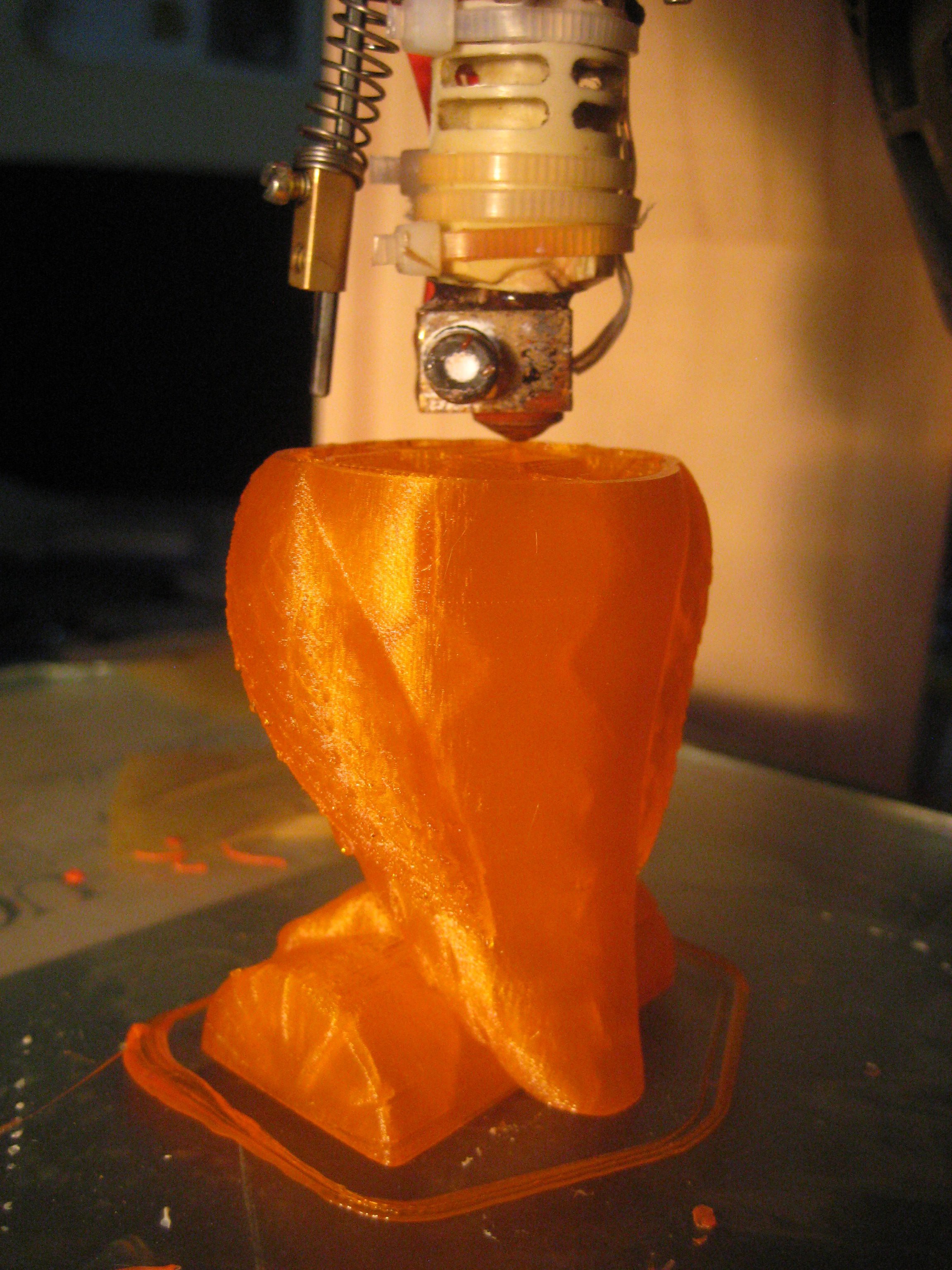
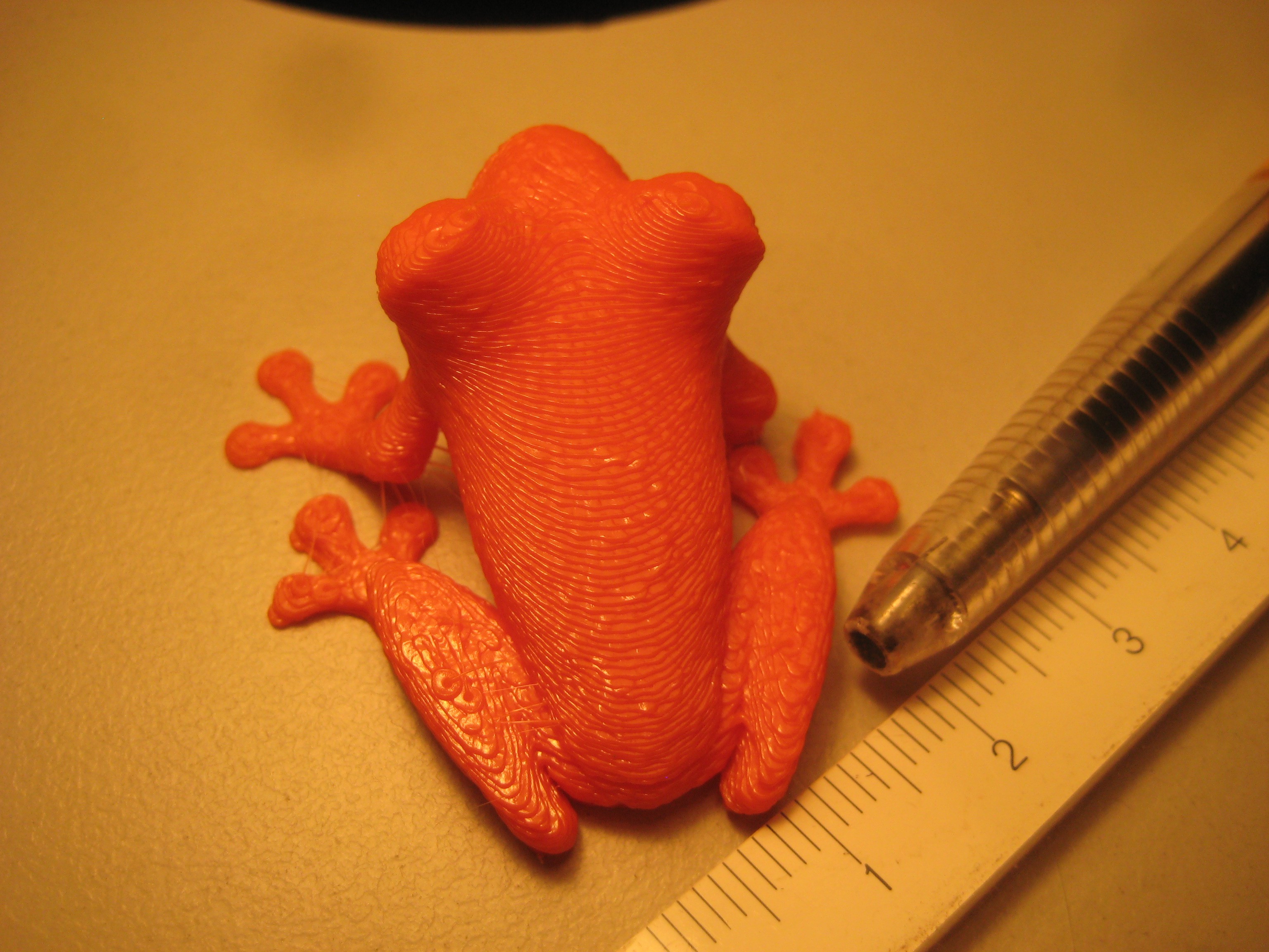
So far it prints very nicely at low speeds (30 mm/s, 0.1 mm layer height, pla, 0.5 mm nozzle, 3000 acceleration set in firmware) EDIT: Looking back it wasn't actually doing 200mm/sec, as the arduino couldn't calculate the moves fast enough.
![]()
At higher speeds the limitations of the design become apparent ( 200mm/s, 0.2 mm layer height, pla, 0.5 mm nozzle, 3000 acceleration set in firmware)
EDIT: Looking back it wasn't actually doing 200mm/sec, as the arduino couldn't calculate the moves fast enough.
![]()
The ratio between the steppers and the upper arms is 1:14. Ideally it would be in 1 to 20 - 50 range. As long as the machine runs slow and the microstepping can really make its effects apparent. I wouldn't say that there's any fatal design faults in the icepick, but that 1:14 ratio is a bit of a snag. I have some ideas about using braided fishing line and some very small pulleys, if used, the big pulleys could be much thinner. Another alternative may be to increase the size of the main pulley, and cut off a piece off the bottom which isn't required, but increasing the pulleys may make the design a bit too bulky.
Ideas are welcome! Leave them in the comments below :)
-
slow going..
09/27/2014 at 02:08 • 0 commentsThe semester break has come and gone. I haven't done anymore work on the project. Studies are moving too fast! Meaning I can't spend time on the project. So it will be shelved till further notice. I will definetly complete the project don't worry ;)
-
More Iterations :)
08/09/2014 at 11:07 • 0 commentsParts arrived sooner than expected! I also got more filament from Diamond Age Solutions so now I can continue.
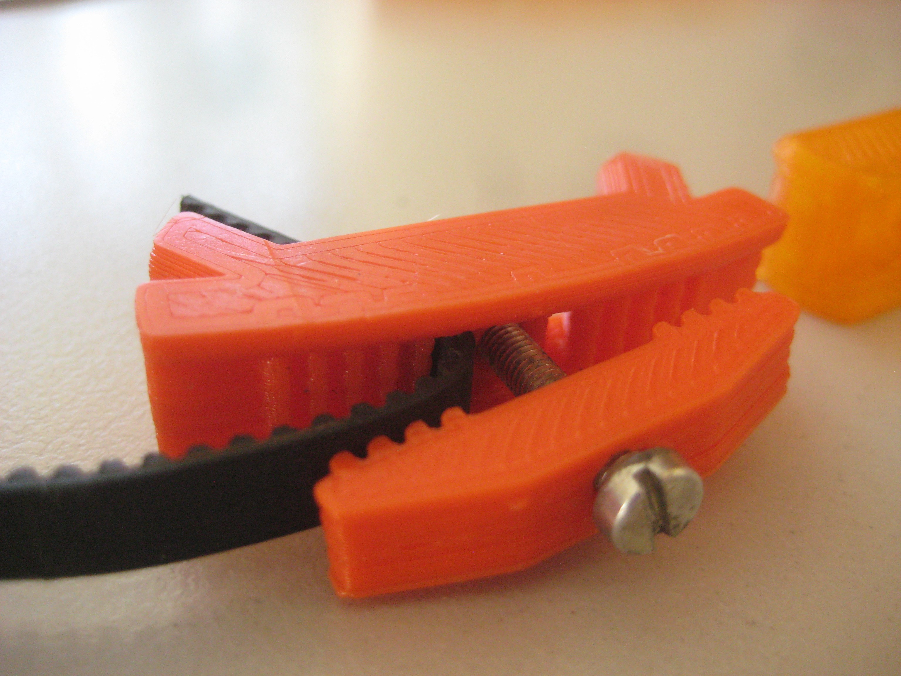
Iteration 5 of the pulley belt clamp, I'm only printing a fraction of the pulley to save on printing while I test what works best. I'm satisfied with it. It holds the belt very tight, is robust and easy to print and adjust.
![]()
The upperarms also went through a few iterations and I printed a couple. I'll get some pictures up when I get a complete set.
As with all my project files for the Icepick Delta, they can be found on the github repository.
Any questions or suggestions, please do ask!
-
Progress!
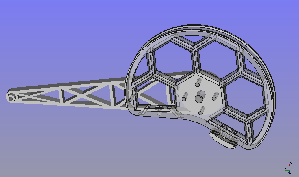
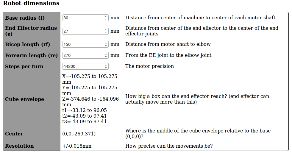
07/14/2014 at 19:30 • 0 commentsThe target printable area will be at least the standard 200mm cube. The Delta Robot Forward/Inverse Kinematics Calculator has been very helpful. with the configuration as below, we'd will theoretically have a working cylinder of at least 200mm in diameter and 200mm high. That's the theory anyhow, and theory and practice, are too often not the same ;)
We got most of the cad drawings done. What we have so far is on the Github repository. I'll start printing parts when replacements for my printer arrive in the next few days.
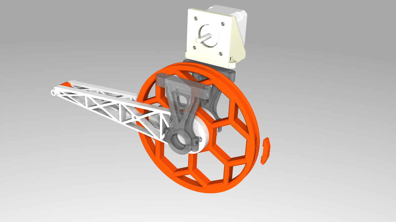
One thing that we would like to do is replace the standard traxxas rod ends with printable universal joints. I have a few ideas which I will be testing.
![]()
The firepick project calculations came out at a resolution of 0.0201mm when using a 10:1 ratio on the stepper motor to the upper arm which was 100mm long. To get the desired build volume, I had to make the upperarms longer. To maintain accuracy I settled on a ratio of 14:1. Using the accuracy information as above from the firepick project and pulley ratios, the accuracy should be 0.0215mm. When I did the calculations by hand I came out with an accuracy of +/-0.04mm, which should be ok. If my accuracy calculation result of +/- 0.04 mm, which has a generous amount of tolerance, is wrong, and the calculations based on the firepick of +/- 0.0215mm are correct, that would be even better. The catch here is that I am assuming x16 microstepping (on 1.8 degree steppers), which may not actually perform as well as I'd like.
Special thanks goes to Matt Kimbal for teaching me how to use FreeCad and all his wonderfull input who without this project would not have been.
![]()
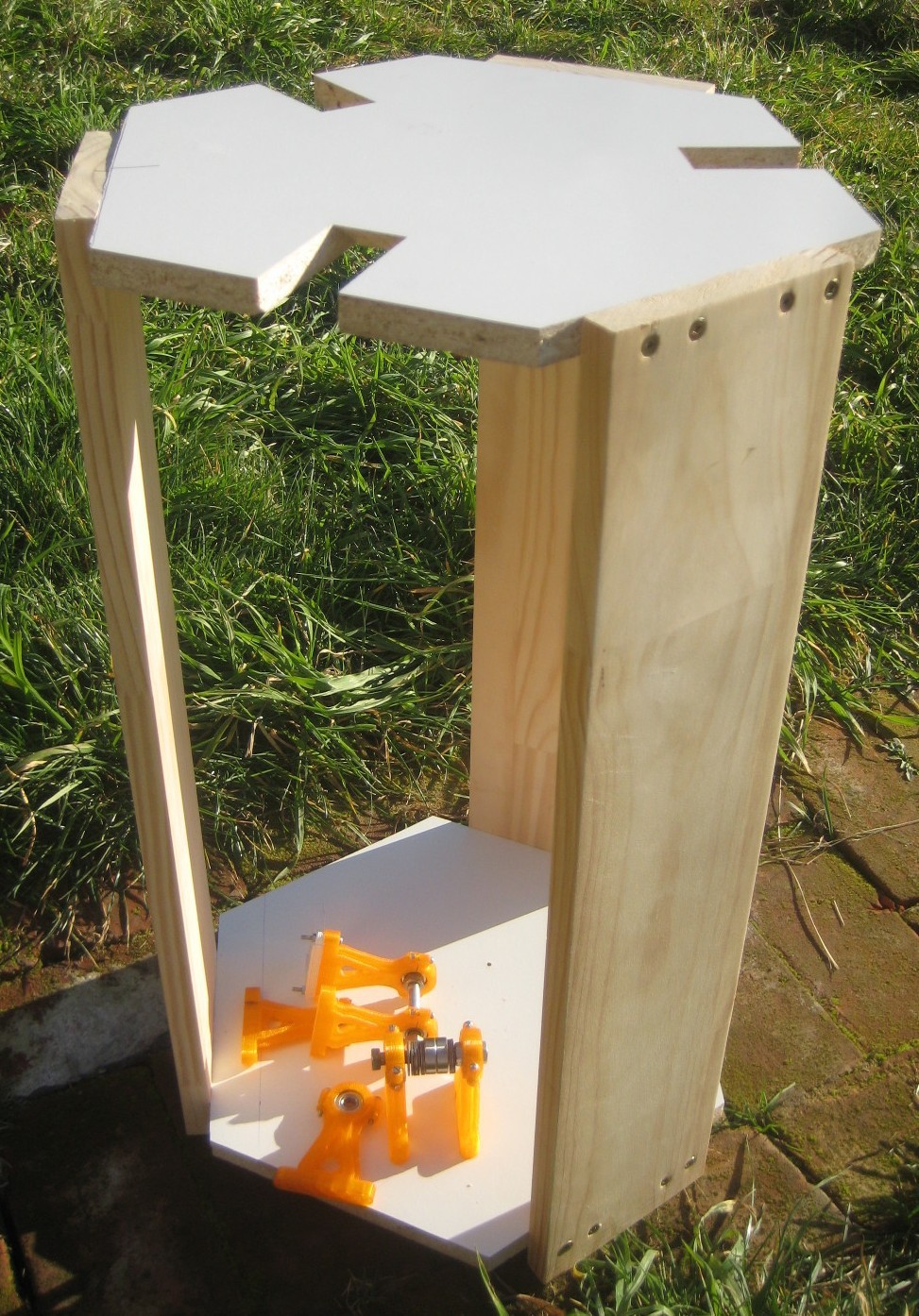
I got some of the frame put together over the weekend. The semester has started now, so I expect not to have much time to work on the project. I ordered parts which have an expected arrival time of 20 to 45 days which should be in time for the mid semester break :P
![]()
The frame does have a little flex when force is applied. I might add some reinforcing pieces later.
Repstrapping with this design shouldn't be too hard, given you have access to a lathe like me. It's an attractive option, as creating round parts on a lathe is not difficult ;) Some bits of custom wood for the upper arm, a printed part for the end effector and motor mounts and I should be all good to go!
Icepick Delta
A highly experimental open-source 3D printer with a rock bottom bill of materials