Capt. Flatus O'Flaherty ☠
-
In Actual use
07/16/2018 at 15:57 • 0 comments![]()
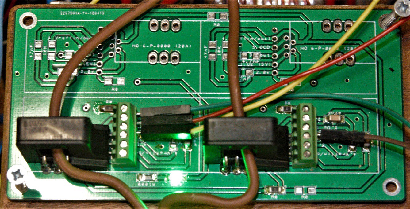
Incredibly simple. Incredibly effective ……. This PCB is wired for 2 channels.
Green wire = earth
Red wire = 5V
Yellow wire = signal to analogue read pin.
-
Testing the sensors on a robot
05/09/2018 at 15:55 • 0 commentsFirstly, the code that worked on the Arduino uno did not work on the 3 core TC275, probably because of a speed issue, but I never found out exactly why!
The new code, for CORE 1 is:
  ic = 0;
  while (ic < intervalFive)   // AC 50 hertz is equivalent to 20 ms per AC cycle
  {
    ic++;
    delay(1);                 // Capture data over one complete AC cycle.
    currentSensorValueFive = analogRead(A3);
    currentSensorValueSix = analogRead(A2);
    if(currentSensorValueFive > maxCurrentValueFive)
    {
      maxCurrentValueFive = currentSensorValueFive;
    }
    if(currentSensorValueSix > maxCurrentValueSix)
    {
      maxCurrentValueSix = currentSensorValueSix;
    }
  }
//////////////////////////////////////////////////////////////////////////////
    runningmaxCurrentValueFive = (maxCurrentValueFive - 523)/80;
    runningmaxCurrentValueSix = (maxCurrentValueSix - 523)/80;
    maxCurrentValueFive = 0;
    maxCurrentValueSix = 0;
.... And CORE 0:
void torqueDifferential()
{
  // Make RH wheel turn slightly faster if current in LH wheel too high. Three and five is LH and Four and six is RH.
  // Weighting is 6:4.
  intervalFour = ((0.60*intervalFour) + (0.40*(intervalFour * (runningmaxCurrentValueSix / runningmaxCurrentValueFive))));
}
Core 0 runs without any 'delays' and controls the motors with 'step' and 'direction'.
The whole point of the current sensor gadget was to override positional errors created by situations where one of the drive wheels goes over a rock, which causes it to travel further in terms of rotational distance. The Agri - robot, the WEEDINATOR, needs at least one wheel with positional control to get quick and accurate translation between one grid of plants to the next without having to rely so much on GPS / accelerometers etc.
A ramp was used to create a positional error on one of the wheels and then the test was repeated with torqueDifferential() as above:
-
Example Code
05/07/2018 at 15:20 • 0 commentsThe code below gets readings from 2 sensors on AC 'live' wires. In the UK, our AC supply is 50 Hertz so to get the peak amps at any given time, the wave form needs to be sampled over 20 micro seconds. NB. The sensors have not been calibrated.
int i=0; int sensorValueOne; int sensorValueTwo; float maxValueOne; float maxValueTwo; float runningMaxValueOne = 0; float runningMaxValueTwo = 0; unsigned long currentMillis = 0; unsigned long previousMillisOne = 0; unsigned long previousMillisTwo = 0; int intervalOne = 0; const int intervalTwo = 1000; int millisCalcOne =0; int millisCalcTwo =0; int ACFrequency = 50; // Hertz void setup() { Serial.begin(115200); intervalOne = 1000 / ACFrequency; // Capture data over one complete AC cycle. } void loop() { currentMillis = millis(); millisCalcOne = currentMillis - previousMillisOne; millisCalcTwo = currentMillis - previousMillisTwo; i++; //Serial.print(" i: ");Serial.println(i); sensorValueOne = analogRead(A0); sensorValueTwo = analogRead(A1); if(sensorValueOne > maxValueOne) { maxValueOne = sensorValueOne; } if(sensorValueTwo > maxValueTwo) { maxValueTwo = sensorValueTwo; } ////////////////////////////////////////////////////////////////////////////// if (millisCalcOne > intervalOne) { runningMaxValueOne = (maxValueOne - 523)/80; runningMaxValueTwo = (maxValueTwo - 523)/80; //Serial.print(" LHS amps max: ");Serial.print(runningMaxValueOne,2);Serial.print(" RHS amps max: ");Serial.println(runningMaxValueTwo,2); maxValueOne = 0; maxValueTwo = 0; i=0; previousMillisOne = currentMillis; } if (millisCalcTwo > intervalTwo) { //Serial.print("sensorValueOne: ");Serial.print(sensorValueOne); Serial.print(" LHS amps max: ");Serial.print(runningMaxValueOne,2);Serial.print(" RHS amps max: ");Serial.println(runningMaxValueTwo,2); previousMillisTwo = currentMillis; } } -
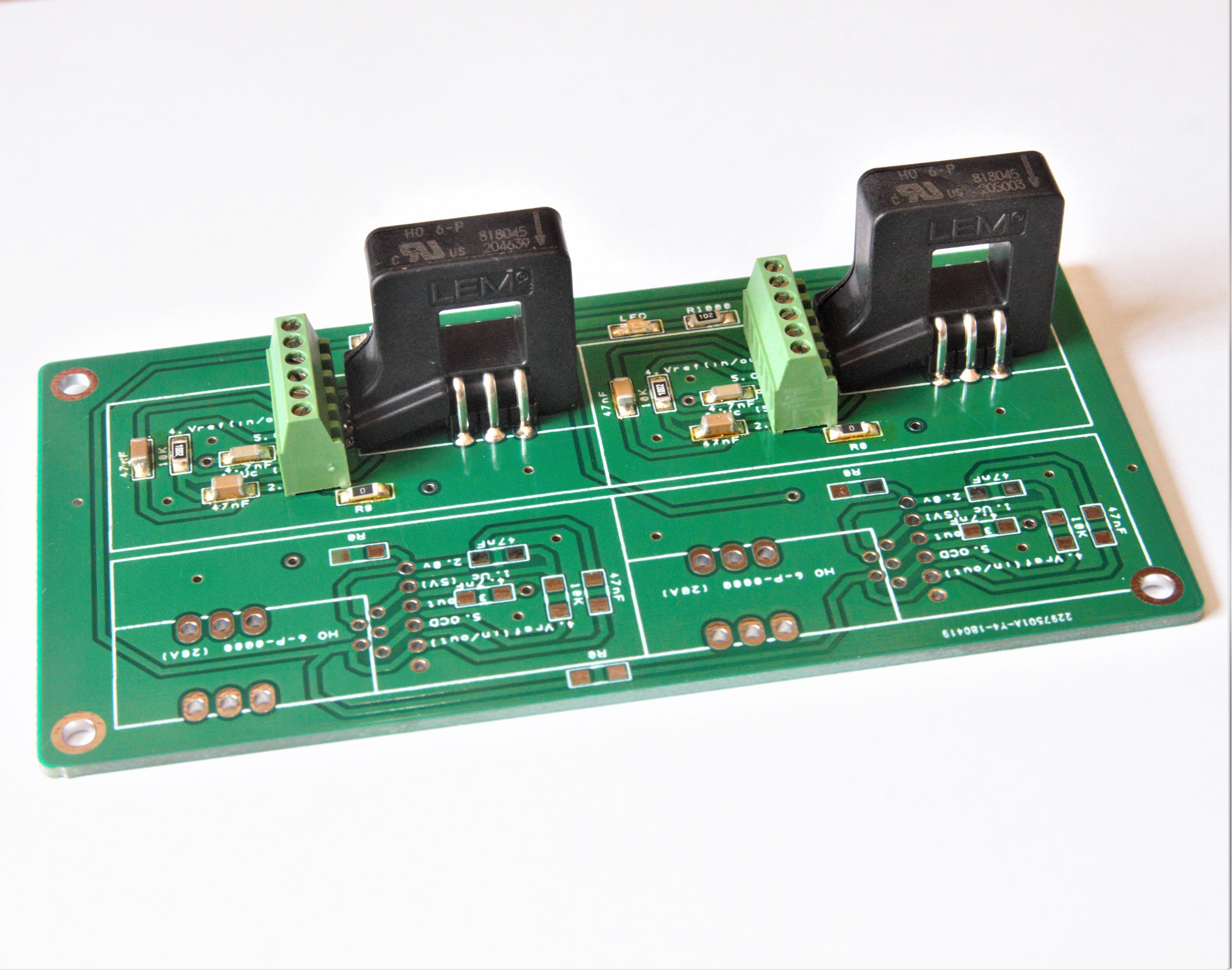
Boards arrived and Populated
05/06/2018 at 10:46 • 0 comments![]() Quickly solder on the components and ready to test.
Quickly solder on the components and ready to test.![]()
-
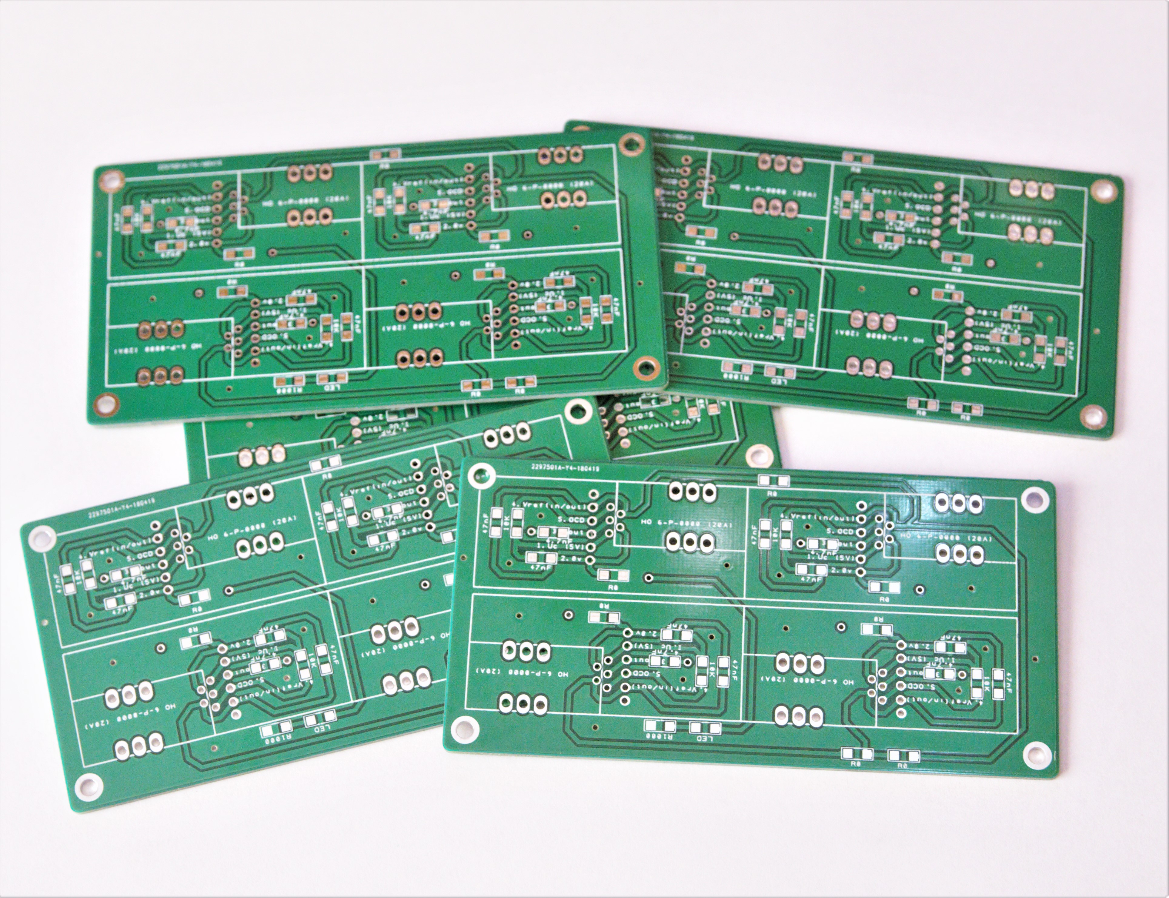
PCBs in the Post
05/01/2018 at 10:17 • 0 commentsGerber files have been sent to JLCPLC.com , China. Now waiting for PCBs to arrive ..... I cant believe these PCBs cost 0.4 USD each ..... How do they do that? ..... And the quality is really good.
4 Channel Non Invasive Current Sensor for Robots
If your motor drivers do not output current / torque data then current sensors may be needed.
 Quickly solder on the components and ready to test.