Carl Bugeja
-
4B Issues
12/31/2019 at 07:25 • 0 commentsIn this video I tried to explain all the issues I have encountered while building my 4B transformer robot.
-
First Test with an onboard battery!
12/17/2019 at 21:43 • 1 commentThis is 4B's first test with an on-board battery. In this video, I tested how it opens and closes into a ball, the walking algorithm and also a very rough open-loop rolling algorithm.
-
4B is BACK!
12/14/2019 at 14:57 • 0 commentsThis is the build video of 4B, a robot i started working on last year but had to stop because of the other projects that I had. This robot has 4-legs with a total of 12DOF, and what's special about it is that it can fold in a 6cm diameter ball!
The full test video is coming next week :)
-
It's coming back!
10/01/2019 at 21:05 • 1 commentAfter a long pause from this project, I happy to announce that 4B is coming back! Today I got these fresh new PCBAs!
![]()
I started this project last year, but I had to stop working on it because of all my other projects that I started 😂 As you know from my last log I had some issues with the soldering of this board. There was an issue with the plating of the old PCB and in fact the programming pads were even getting disconnected with minimal amount of heat (these PCB were order from a very cheap PCB manufacture which I will not mentioned). So now to make life a little easier and gain more time working on my other projects, my new PCB manufacture PCBway offered to sponsor its full assembly!
Stay tuned for updates
-
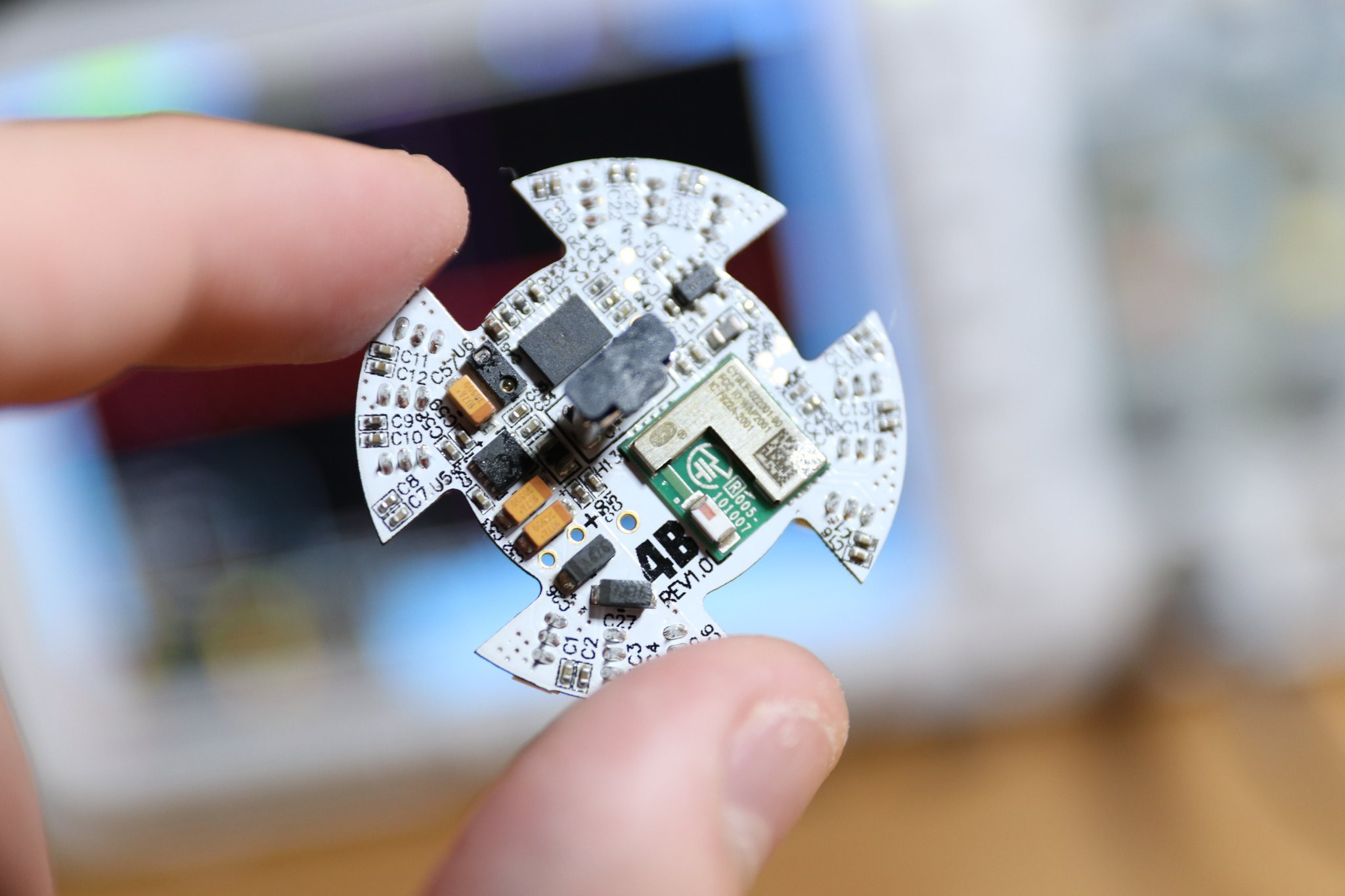
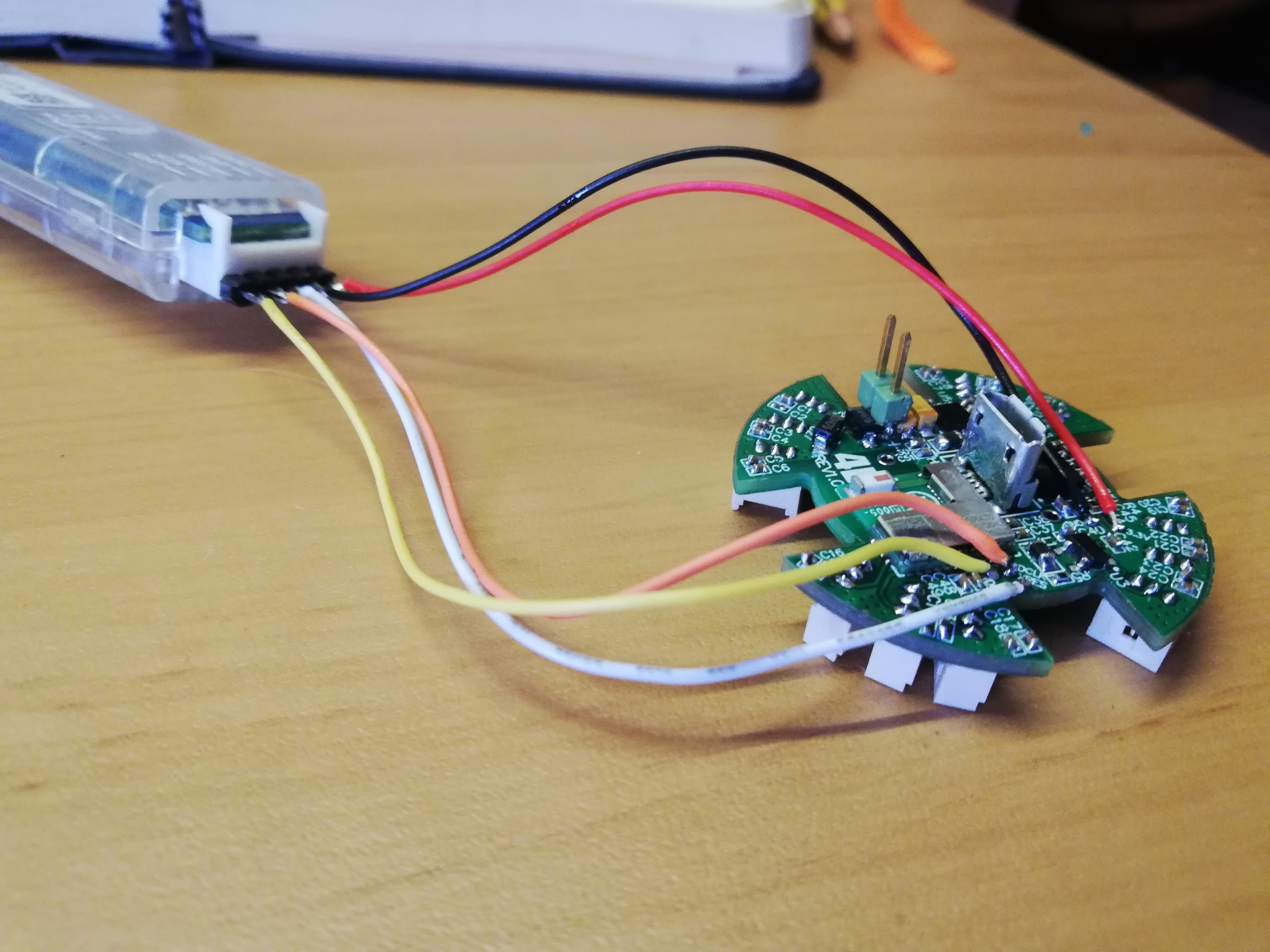
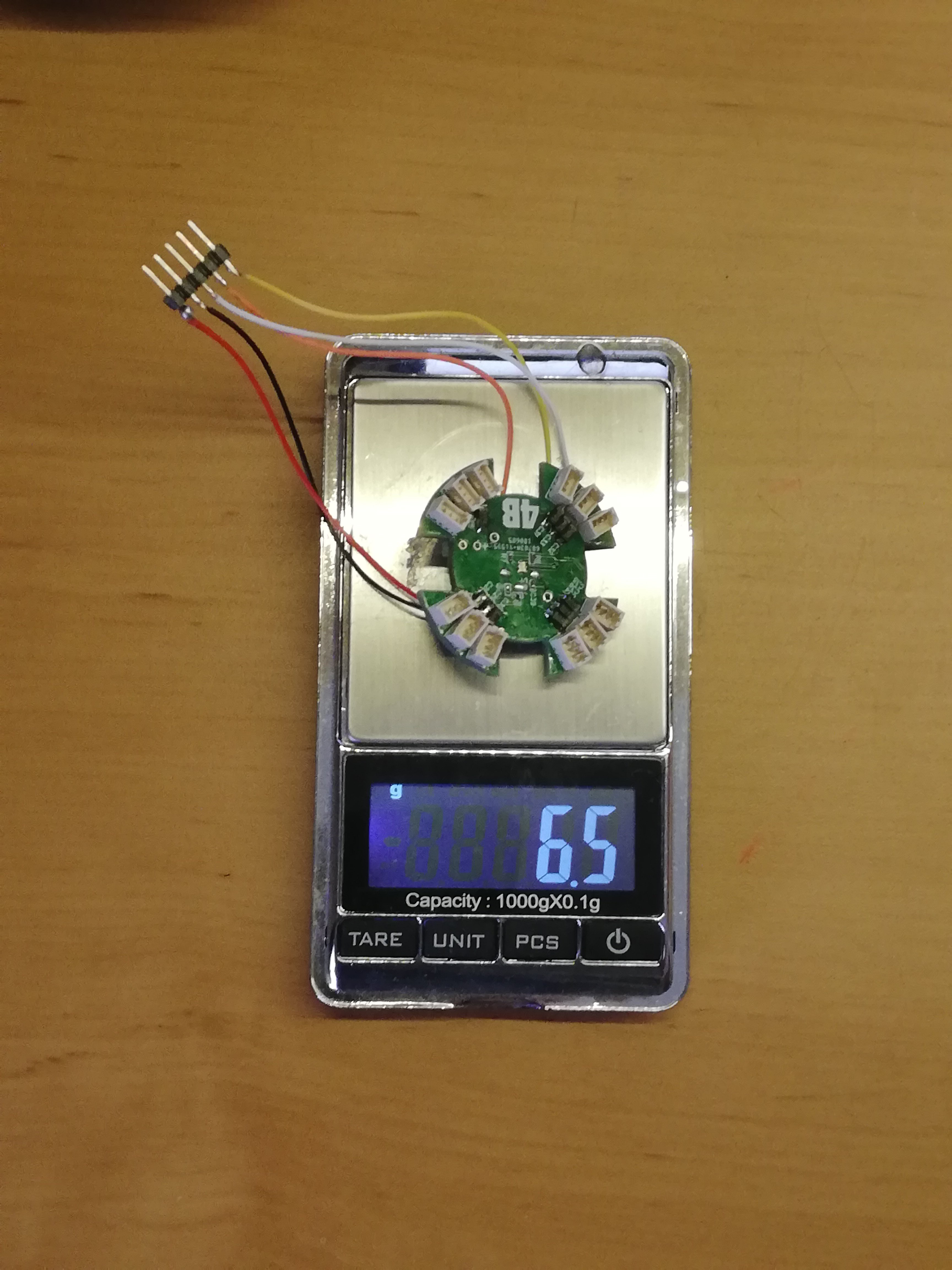
PCB Assembly Update
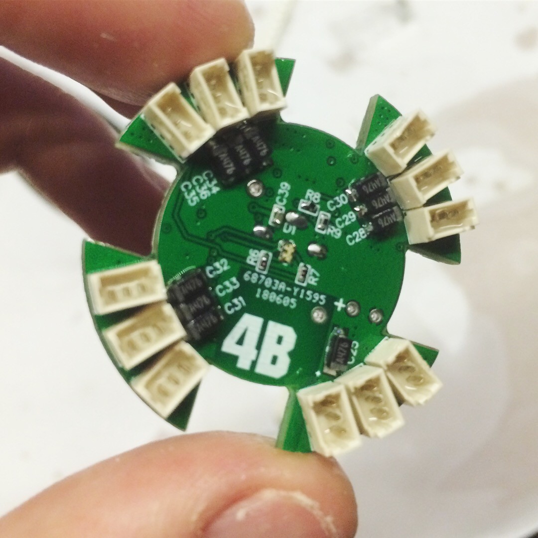
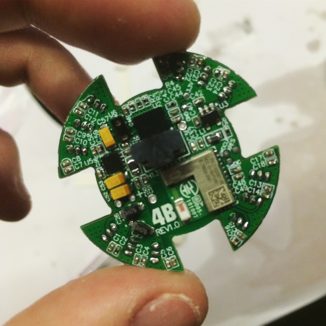
07/21/2018 at 22:49 • 0 commentsToday i have continued debugging the pcb for any soldering bugs and test all the circuitry. The pcb ended up weighing 6.5 grams. This includes the programming header. This can be eliminated by designing a programming jig which will definitely be handy to have.
![]()
![]()
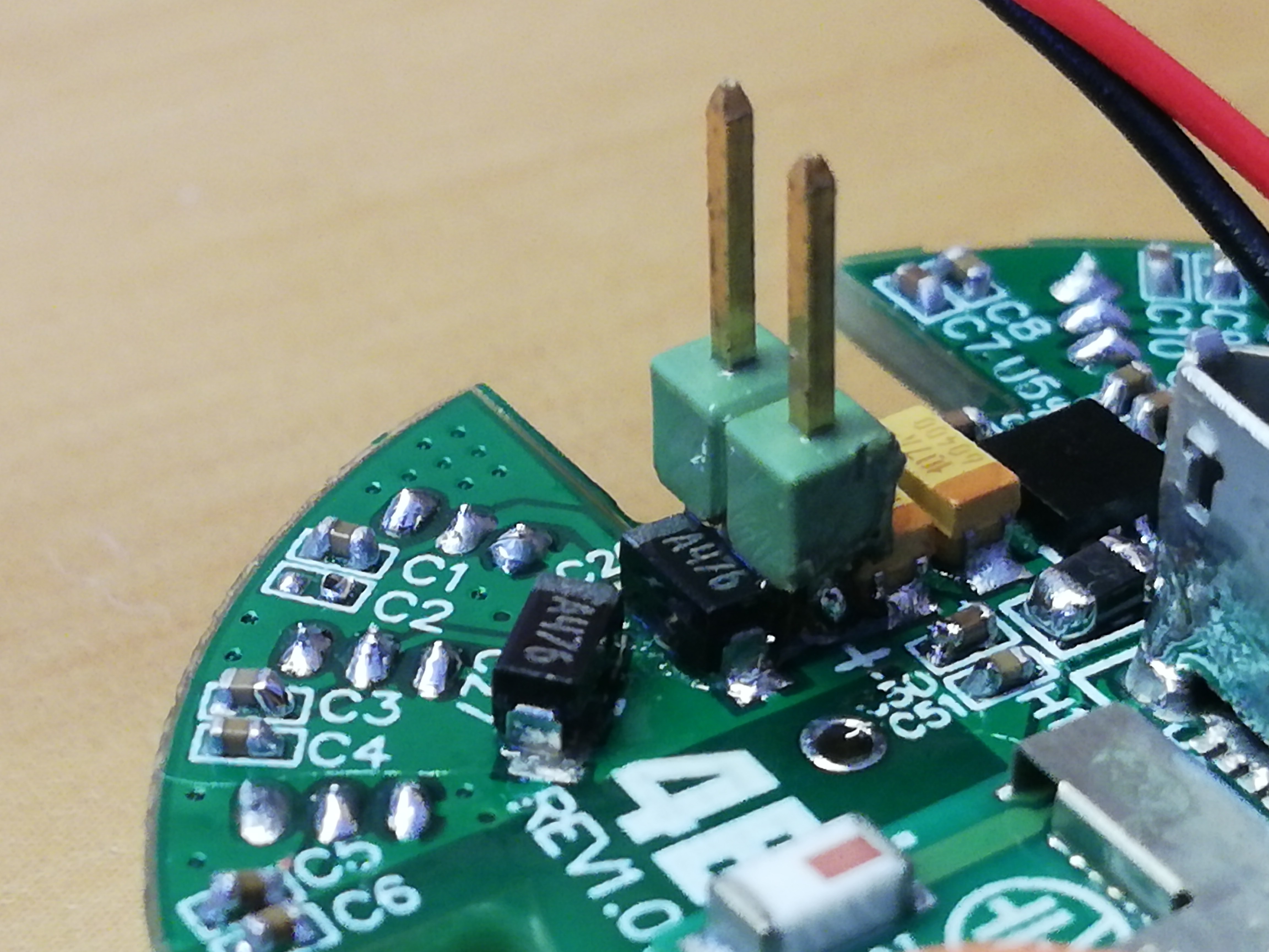
For now, i have soldered a temporary battery header until i configure the sleep mode.
![]()
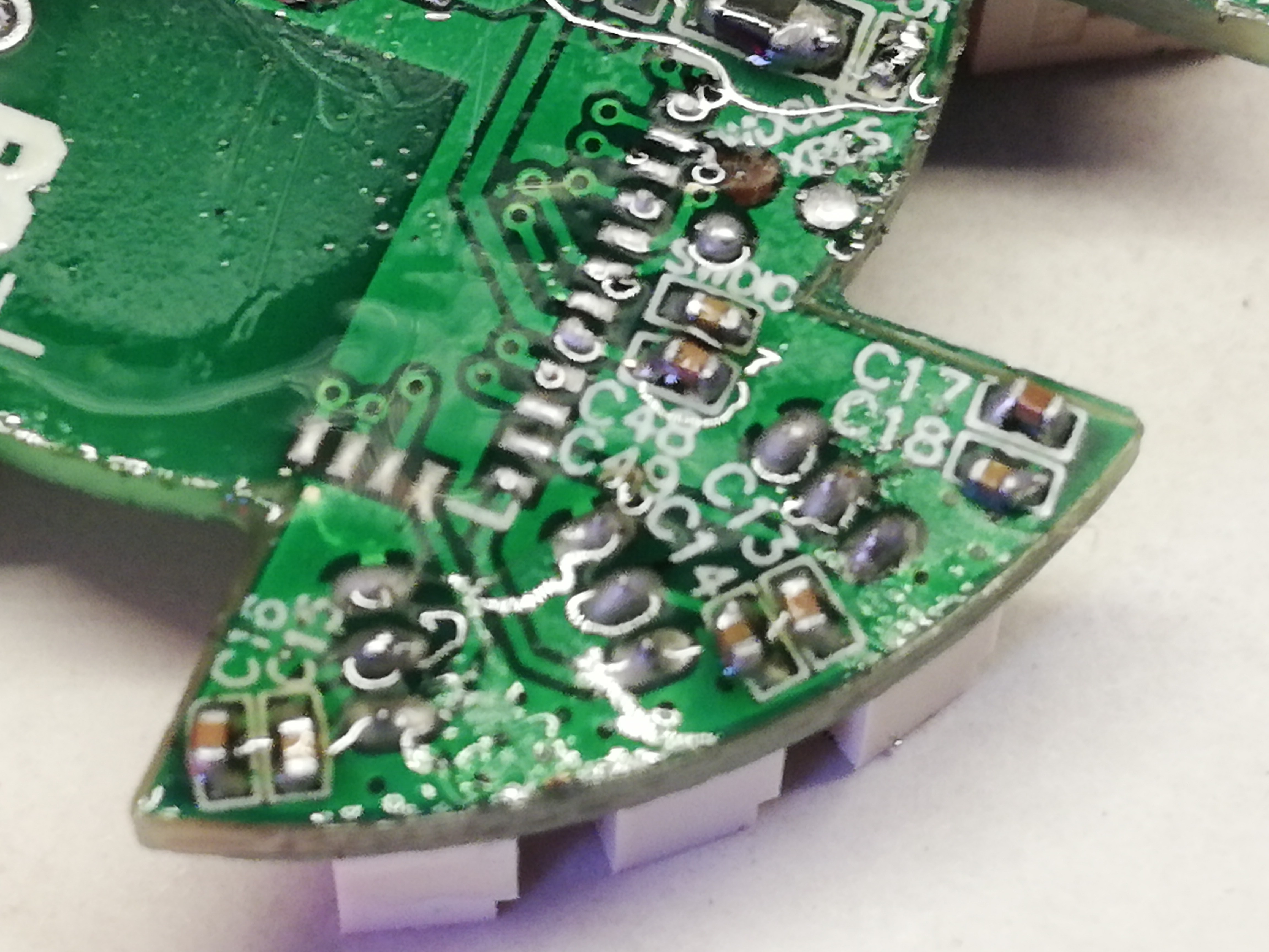
Unfortunately one of the programming pads got disconnected while doing rework on the BLE module 😐 this means that i have to start over with a new pcb.
![]()
-
PCB Assembly
07/19/2018 at 21:54 • 2 commentsAll the components have arrived and today i started soldering the pcb!
I’m quite happy with the result 🙂 The only issue i have found till know is with the USB socket. For some strange reason the slots for its alignment pins were not generated in the NC drill files. So i had to chop off these pins from the socket and soldered them with the pad.
![]()
![]()
![]()
-
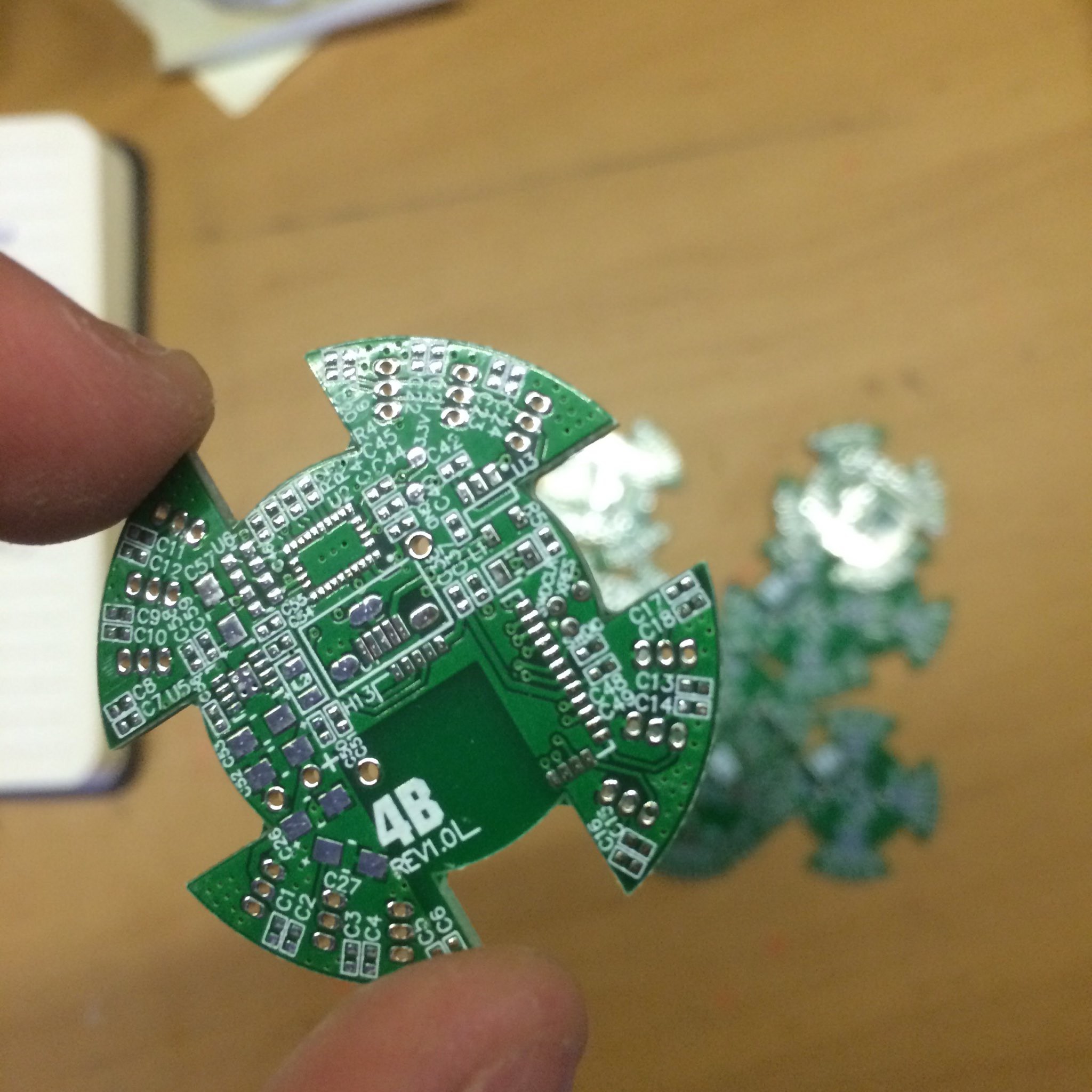
PCBs have Arrived!
06/14/2018 at 18:33 • 2 commentsThe tiny pcb for my 4B robot project has just arrived! Only a few components remaining to arrive so that i can start soldering the whole board.
![]()
It seems to fit perfectly in place!
![]()
-
PCB
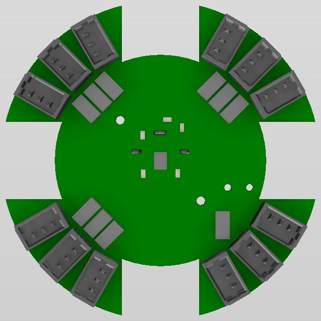
06/04/2018 at 23:08 • 0 commentsThese are the 3d renders of the 36*36mm 4-layer PCB board for the 4B robot. It contain the CYBLE-022001-00, a tiny ble module in a 10*10mm package. The BNO055 IMU which has an internal fusion block and the VCNL4040M3O as the proximity sensor. Servo connector are all placed around the edge, closer to the servo motors. It also has a vertical usb connector and the MCP73831T LiPo battery charger with a status rgb led in the middle.
![]()
![]()
-
Electronics System Architecture
06/02/2018 at 16:03 • 3 commentsSo this is where the fun begins. Design all the electronics of 4B on a 36*36mm pcb. To do so I needed to narrow down the number of components to the bare minimum. And these are the main modules:
- MCU integrated with BLE Module
- 9-axis IMU
- Proximity Sensor for z-axis control
- Connectors for the servo-motors
- 3.3V LDO voltage regulator
- USB LiPo battery charger
The MCU will be responsible:
- Bluetooth communication
- Reading data from the IMU and proximity sensor on the I2C bus.
- Calculating the inverse kinematic equations to actuate the robot kinematic chain
- Setting out 12 PWM waveforms to the servo-motors
That's a bit too much to handle for one MCU, but given the available space on the board it has to work.
-
Assembly
06/01/2018 at 05:13 • 1 commentThis is the assembly video of the 4B robot:
I'm quite happy with the way the design turned out.
All parts are 3d-printed with nylon plastic and their finish looks beautiful. Some of the linkages feel a little flexible but that can be easily fixed by making a thicker edge. The servo-motor hubs that are integrated with the linkages fit perfect inside the servo splines and the tiny SMF681X-ZZ bearings snaps firmly in place.
The next step for this project is to start designing the electronics and pcb. Having a custom pcb in place will tidy the wiring mess so that I could test the robot more easily.