 silver2row
Hello...
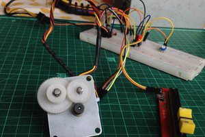
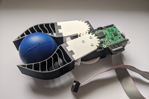
I am going to add the second motor soon. Enjoy...
Seth
P.S. Outside of the other board used in this project, I am attempting to use the https://cdn.velleman.eu/downloads/25/wpi409a4v01.pdf board from Velleman Electronics for testing.
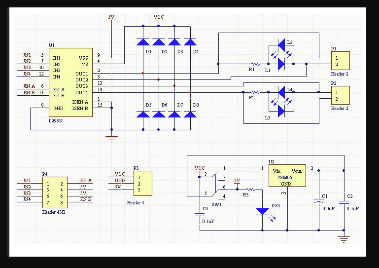
This is a L298 motor driver from Open-Electronics.org and a BeagleBone Black with Python software
Already have an account? Log in.
To make the experience fit your profile, pick a username and tell us what interests you.
Hello...
I am going to add the second motor soon. Enjoy...
Seth
P.S. Outside of the other board used in this project, I am attempting to use the https://cdn.velleman.eu/downloads/25/wpi409a4v01.pdf board from Velleman Electronics for testing.
L298_schematic.PNGschematic of this particular board...Portable Network Graphics (PNG) - 308.06 kB - 05/07/2018 at 03:15 |
|
|
Attach the wiring from the BBB while it is unplugged and there is no power going to the BBB to the L298 motor driver from Open-Electronics.org.
Go to bb-imager-rs online at https://github.com/beagleboard/bb-imager-rs. If your pins are configured for other uses outside of GPIO functionality, use the DTS files to initiate them or find what is available via gpioinfo. Right now, my kernel is 5.10.168-ti-r83 under a Debian/GNU Linux distro from beagleboard.org. It is of Bullseye and not Bookworm. There are other images available, depending on your needs, from the forums. You can search, under forums.beagleboard.org, latest-images and that search should bring you to a couple of images for Bullseye, Bookworm, and Trixie (I think).
So, that connection with this software will get you up and running quickly:
// I will work soon on making some moderate source code for this driver

// line  12:      "P8_12"      "P8_12"   input  active-high [used] from gpiochip1
// line  13:      "P8_11"      "P8_11"   input  active-high [used] from gpiochip1
// line  14:      "P8_16"      "P8_16"   input  active-high [used] from gpiochip1
// line  15:      "P8_15"      "P8_15"   input  active-high [used] from gpiochip1

// Although gpioinfo states these pins that are available as an input, you can
// set the pin(s) as output in source code

// So, something like these ideas will help...

#include <gpiod.h>
#include <stdio.h>
#include <unistd.h>

#ifndef CONSUMER
#define CONSUMER    "consumer"
#endif

int main(int argc, char **argv)
{
  const char *chipname = "gpiochip1";
  struct gpiod_chip *chip1;
  struct gpiod_chip *chip2;
  struct gpiod_line *Motor1;

  int i, ret1, ret2;

  // Open GPIO chip
  chip1 = gpiod_chip_open_by_name(chipname);
  if (!chip1) {
    perror("Open chip1 failed\n");
    return 1;
  }

  // Open GPIO lines
  Motor1 = gpiod_chip_get_line(chip1, 20);
  if (!Motor1) {
    perror("Get chip1 and Motor1 failed\n");
    return 1;
  }

  // Open LED lines for output
  ret = gpiod_line_request_output(Motor1, "P8_12", 0);
  if (ret < 0) {
    perror("Request line as output failed\n");
    return 1;
  }

  // Blink a LED
  i = 0;
  while (true) {
    ret = gpiod_line_set_value(Motor1, (i & 1) != 0);
    if (ret < 0) {
      perror("Set line output failed\n");
      return 1;
    }
    usleep(1000000);
    i++;
  }

  // Release lines and chip
  gpiod_line_release(lineLED);
  gpiod_chip_close(chip);
  return 0;
}

// Add and Subtract until completion...this is a starter Script for Bullseye
// on a Beagle Bone Black SBC with an am335x SoC.
If this software only goes forward, stops, and shuts down, let me know. If that is too boring, look below. This software will control initialize, start forward, stop, reverse, and stop, and then shuts down and closes the software as it completes.
#!/usr/bin/python3

import tkinter as tk
import gpiod
import sys

# Short script to handle tkinter and GPIOD initiatives. This should control a LED
# or maybe more like a motor if done correctly...

from time import sleep

# --- GPIO Setup ---
# Define the chip and line number for your Motor Driver

CHIP_NAME1 = 'gpiochip1'
LED_LINE_OFFSET1 = 13
CHIP_NAME2 = 'gpiochip1'
LED_LINE_OFFSET2 = 14

try:
    chip1 = gpiod.Chip(CHIP_NAME1)
    left_line1 = chip1.get_line(LED_LINE_OFFSET1)
    left_line1.request(c, type=gpiod.LINE_REQ_DIR_OUT)

    chip2 = gpiod.Chip(CHIP_NAME2)
    right_line2 = chip2.get_line(LED_LINE_OFFSET2)
    right_line2.request(c, type=gpiod.LINE_REQ_DIR_OUT)

except gpiod.FileNotFoundError:
    print(f"Error: GPIO chip '{CHIP_NAME1}' '{CHIP_NAME2}' not found. Ensure gpiod is installed and you are running on a compatible device.")
    sys.exit(1)
except Exception as e:
    print(f"Error initializing GPIO: {e}")
    sys.exit(1)

# --- Tkinter GUI Setup ---
def toggle_motor():
    val1 = left_line1.get_value()
    val2 = right_line2.get_value()
    new_val1 = 1 if val1 == 0 else 0
    left_line1.set_value(val1)
    right_line2.set_value(val2)
    if val1 == 1:
        left_line1.set_value(0) # Turn Left on
        right_line2.set_value(1)
        toggle_button.config(text="Turn Motor Left")
    else:
        left_line1.set_value(1) # Turn Right on
        right_line2.set_value(1)
        toggle_button.config(text="Turn Motor Right")

def cleanup_gpio():
    left_line1.release()
    right_line2.release()
    chip1.close()
    chip2.close()
    root.destroy()

root = tk.Tk()
root.title("Motor Control")

toggle_button = tk.Button(root, text="Turn Motor Left", command=toggle_motor)
toggle_button.pack(pady=20)

exit_button = tk.Button(root, text="Exit", command=cleanup_gpio)
exit_button.pack(pady=10)

# Ensure GPIO is cleaned up when the window is closed
root.protocol("WM_DELETE_WINDOW", cleanup_gpio)

root.mainloop()
If you are wondering about the schematic of this particular motor driver, see the photos section or see here now:
See the L298N, dual H-bridge section for pin connections that need to be made.
Seth
P.S. Use a 12v battery if available. The motors can handle 2A maximum each forward and backwards. The L298 board can handle 5 to 30V DC.

Hello Again,
I am working on a schematic on KiCad w/ the BBB and this L298 motor driver for ideas.
Seth
I created this project to get people interested in motors and to promote collaboration on this subject.
Seth
 KushagraK7
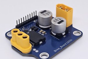
 Pedro Manuel Martín
 Petar Crnjak
Since Adafruit_BBIO has been left in the dust by some, I am learning all over again. It seems libgpiod-dev and gpiod in python3 seem to work now instead of the older, Adafruit_BBIO library.