Michael Mayer
-
successfully picking parts using two servos
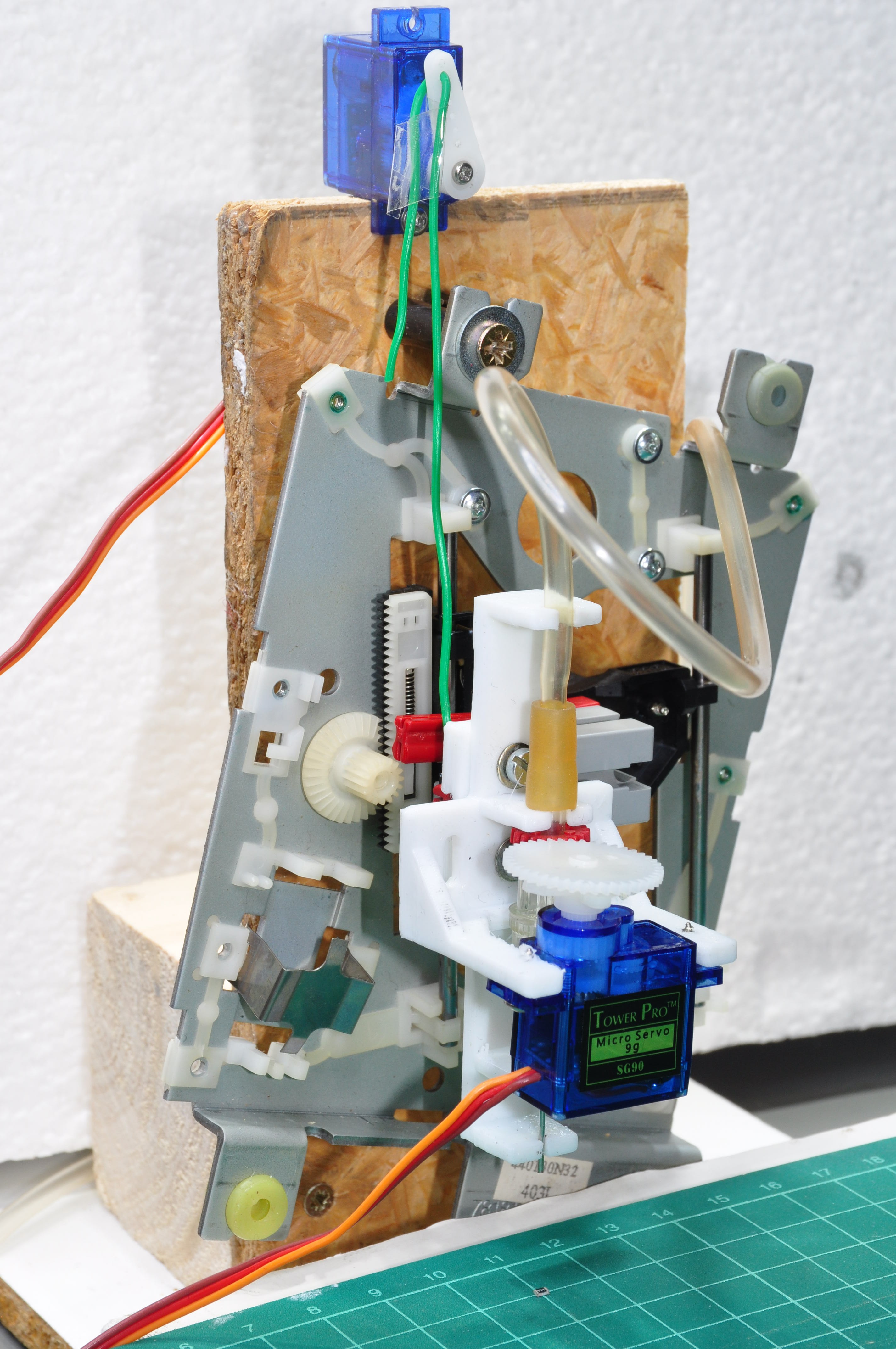
05/14/2018 at 21:57 • 0 commentsI am using an old CD drive for the z axis of my simple test rig. Originally, the sled is driven by a motor (a DC motor, most other drives use stepper motors). But I don't really want to actively drive the sled downward as this only smashes even harder on the poor little SMT part when it hits the PCB. I had issues with cracked resistors on manufactured boards and I would like to avoid that problem.
I tried driving this motor very gently by using the smallest PWM rate I could still get away with - but it still accelerates too much and hits the ground so hard that the part often just jumps away and gets lost on the floor.
A stepper drive would avoid building up an excessive speed, but I still don't have any proper height information and can't tell when I have to stop trying to drive the needle further down.
This is why most other builds use gravity for the downward movements and connect the z sled only loosely to the motor. So do I now: A second servo lifts the z sled by pulling on a string and downward movement happens by gravity only while the speed is still controlled by the servo.
![]()
Et voilà: The parts stay put and can easily be picked up and released by the needle! Have a look (rotation is still controlled manually using a simple servo tester, so don't expect exact 90° movements):
That was easier than expected. So what's the next step? I would love to build a full pick-and-place machine. But that would be a separate project.
To keep things interesting I would opt for a DC motor drive from old inkjet printers for the X and Y axis. These drives allow for closed loop operation and they are remarkably fast and precise.
-
Testing the first prototype
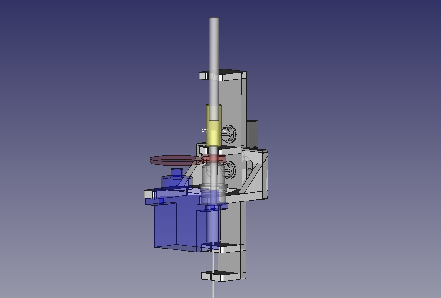
05/13/2018 at 08:47 • 0 commentsI transfered the basic idea into one single 3D-printable part and -surprise, surprise - it works!
This construction was my first time using FreeCAD for designing a non-trival part. Information about the new part/body model in version 0.17 isn't as easy to find and as comprehensive as I would wish for, but it worked. It starts to be a serious alternative to Solidworks now - at least for not too complex tasks.
![]()
The part is designed to be mounted onto a Drylin N17 linear rail. For the first tests I added a similar shaped adapter providing a Fischertechnik groove and used an old CD drive for the z axis.
Rotating the needle using a simple servo tester works quite well for servo rotations up to 90° (+/-45°). If I go further, the servo mount starts to bend up to the point where the gears start to slip. The mount needs more support at the back of the servo.
I expected small misalignments and added 1/2 teeth pitch (~0.8mm at M0.5) to the distance between the gears. This means accepting a noticeable backlash. Fortunately, this backlash turns out to be better than expected given the very generous extra distance between the gears. Not suitable for fine pitch applications, but definitely sufficient for aligning a 0603.
The part was designed to hold the luer lock and the needle by snapping them into partly open holes. This did not work at all. 3mm thick PLA is much stiffer than I expected. Experiments are needed to find the right geometry for snapping connections. Somebody must have researched that before, but I couldn't find anything on this topic yet. Any suggestions?
The needle is forced to be concentric by two supports.They are designed to be snapping connections, but this didn't work I had to cut them open wider than planned. In the end, the support is not as strong as I planned and there is a small amount of excentricity left. Probably ok for 0603, questionable for 0402.
So there is room for improvements. Main lessons for the next iteration so far:
- The servo mount needs a support at the back of the servo.
- researching the right geometry for snapping connections.
- The holder holes need to be a little bigger. +0.3mm of the desired size is the minimum for my printer, +0.5mm is probably better.
- The extra distance between the gears could be reduced. I will try 0.3 or 0.25 teeth pitch next time.
-
proof of concept using Fischertechnik
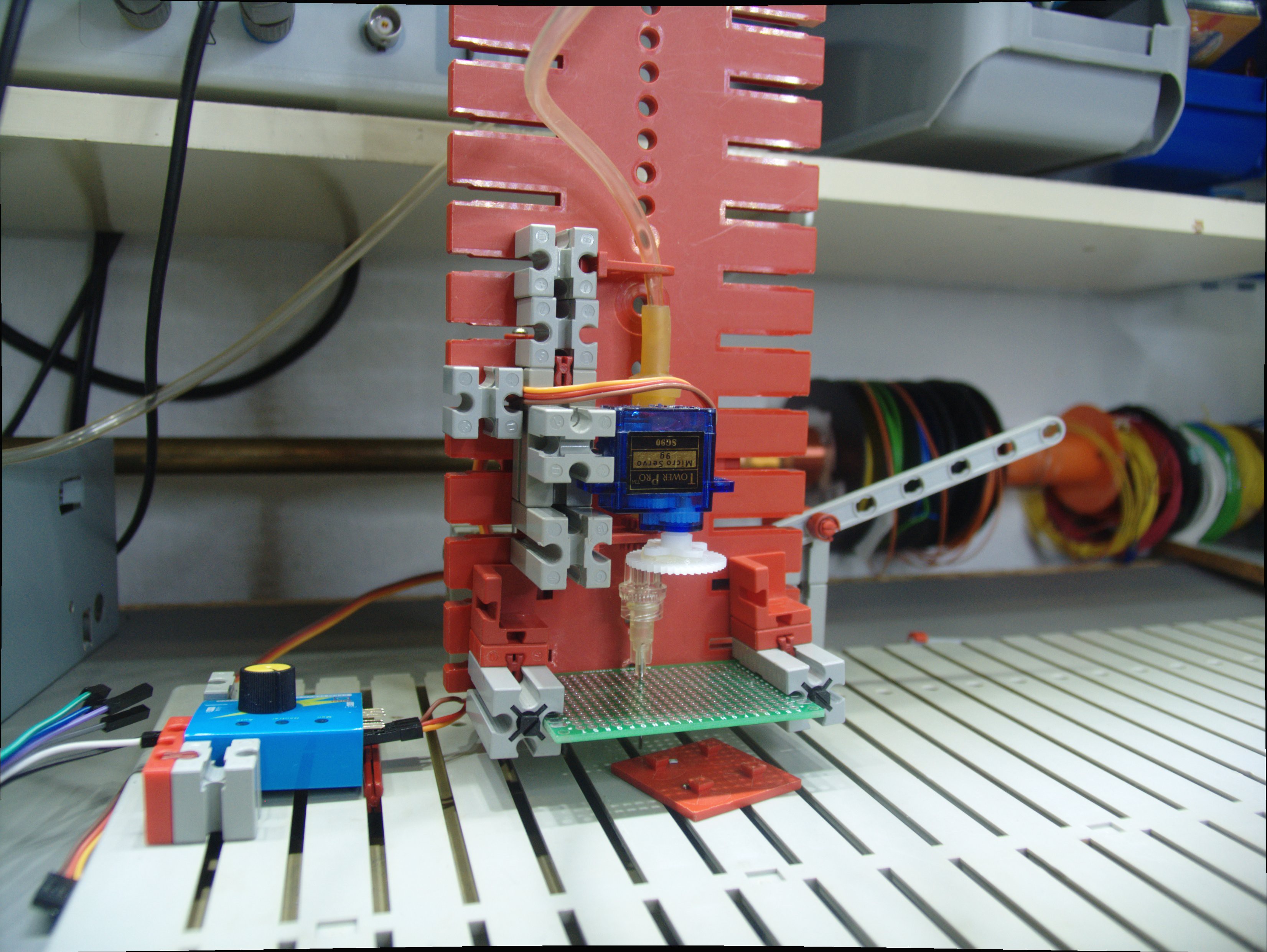
05/11/2018 at 15:07 • 0 commentsTo see if the idea works at all I started with a quick build based on Fischertechnik and some hot glue.
![]()
The small Fischertechnik gear "Riegelscheibe Z20" fits perfectly on the 4mm part of the Luer connector. It is actually a gear with 20 teeth, modulus 0.5mm, and mates with the gears from the cheap china bags (80 gears for 2$).
A 42 teeth single gear from this bag is easily glued onto the cut down 4-way servo horn that comes with the SG-90 servo. The gear hub fits perfectly inside the mounting groove of the servo horn and make aligning and centering of the gear very easy.
The servo is hot-glued to a Fischertechnik element and we are ready for the first test:
The test shows that the needle is still excentric, even when properly connected with a Luer connector. The small piece of PCB helps holding the needle centered, but it is clear that even more guidance will be needed to keep things strait.
Conclusion: The general idea works, but it won't be a high precision device. It will need at least two supports for the needle. 0805 is already easy, 0603 should work but 0402 is questionable, even with two supports for the needle.
Conclusion 2: Fischertechnik is amazing! It makes it very easy to test several construction approaches and to find out with one works best.
-
3D-printing Fischertechnik-compatible parts
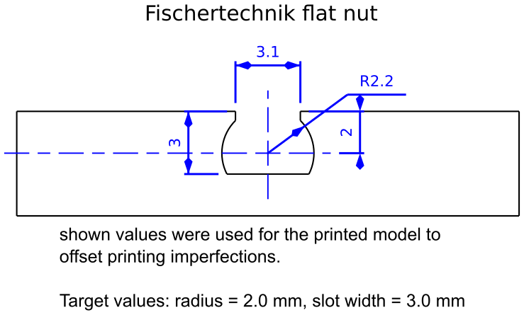
05/11/2018 at 13:56 • 0 commentsA side node to myself to remember how to print parts compatible with Fischertechnik components.
Profile for the shallow flat groove:
![]()
Printing with r=2.0 and w=3.0 results in a too tight fit. r=2.2 and w=3.1 works, but feels a little bit loose. Use r=2.1 and w=3.1 next time.
simple pick-and-place head
A study for a simple pick-and-place head using a servo and an injection needle instead of a hollow-shaft stepper motor and a standard nozzle