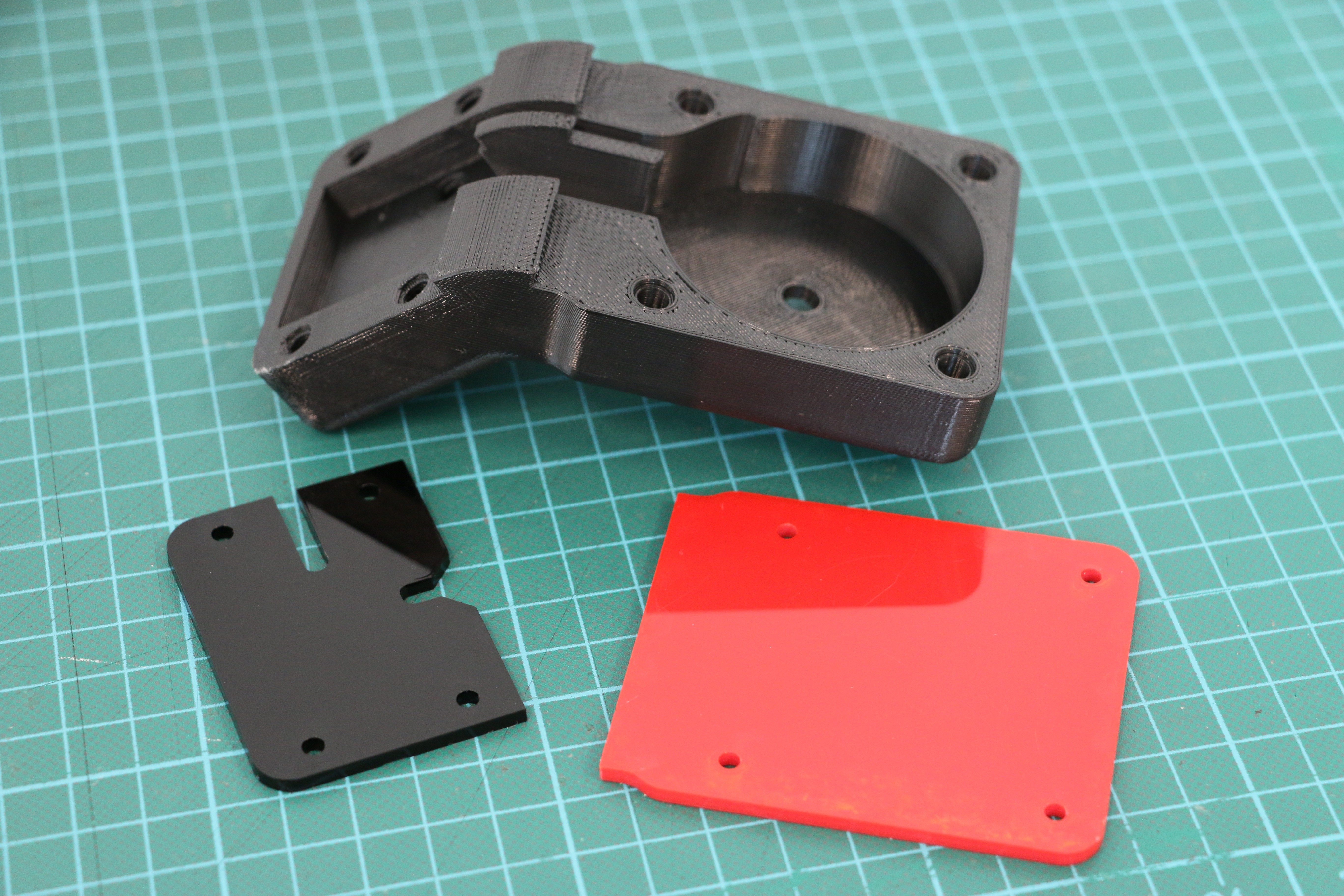
First, 3D print the sensor case and either lasercut or 3D print the Geiger tube and PCB covers.
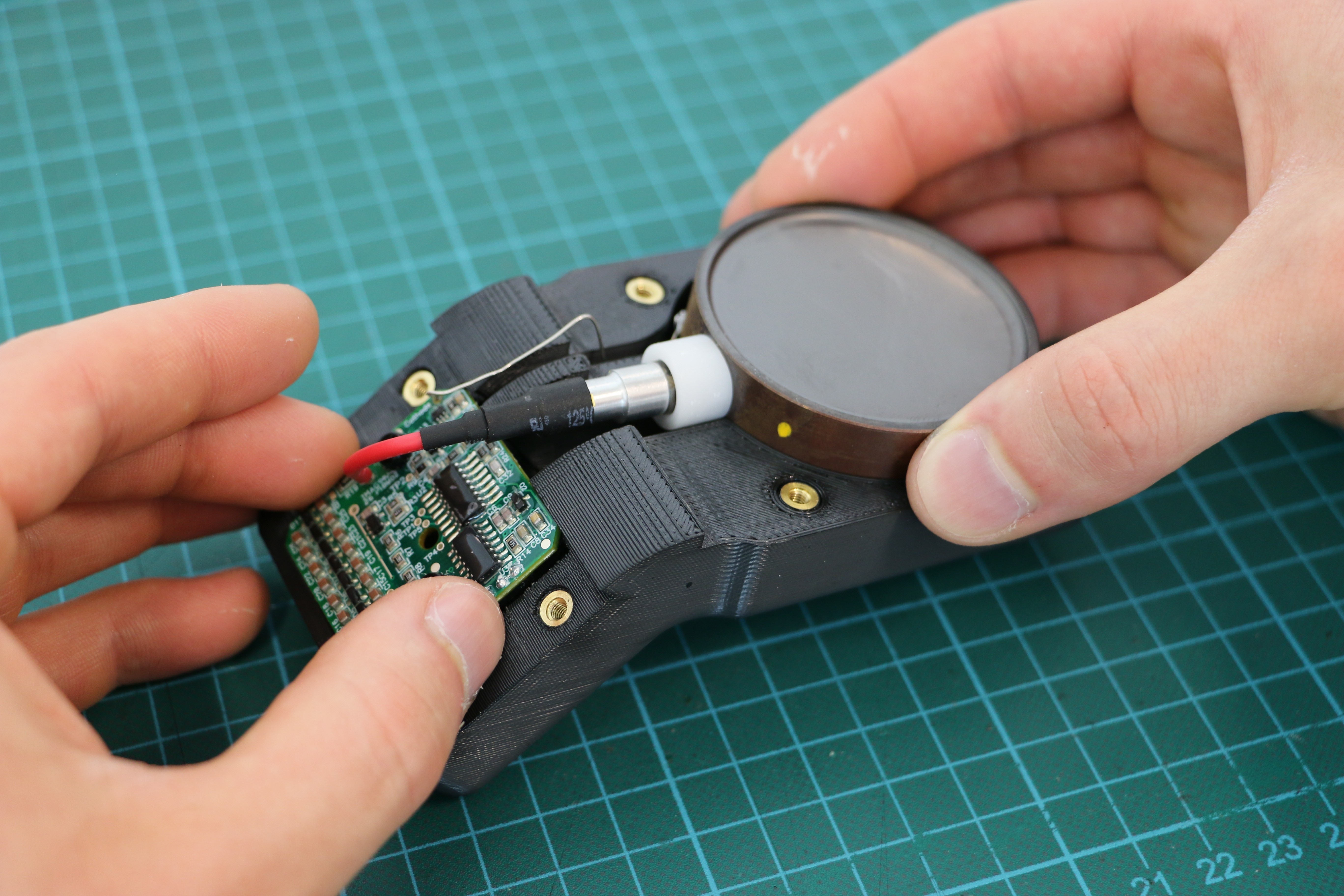
Next, insert the M3 heatset inserts using a soldering iron. Place the insert into the hole, insert the hot iron tip into the insert, and gently press in until it’s flush. The case uses 12 inserts in total, including two in the back.
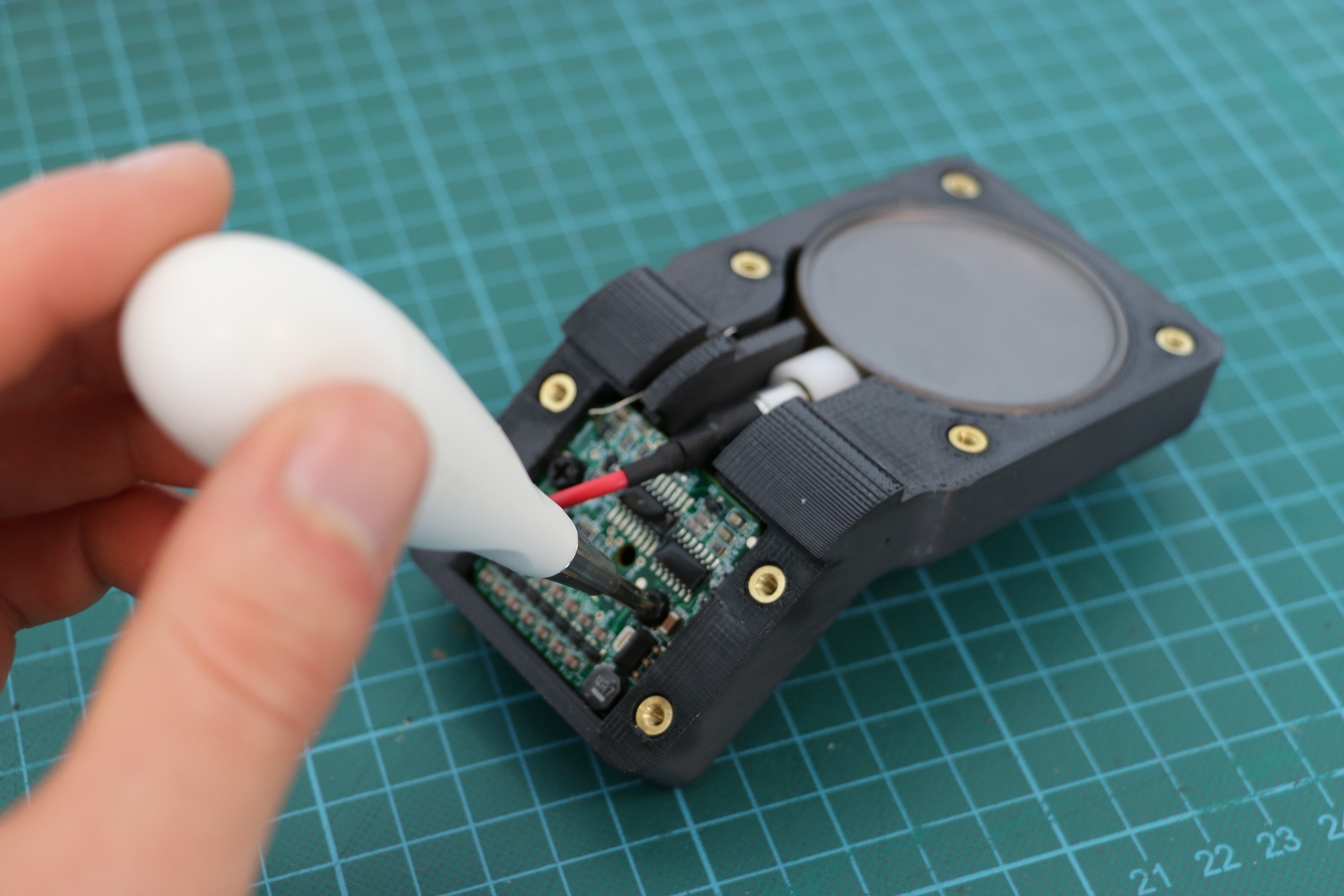
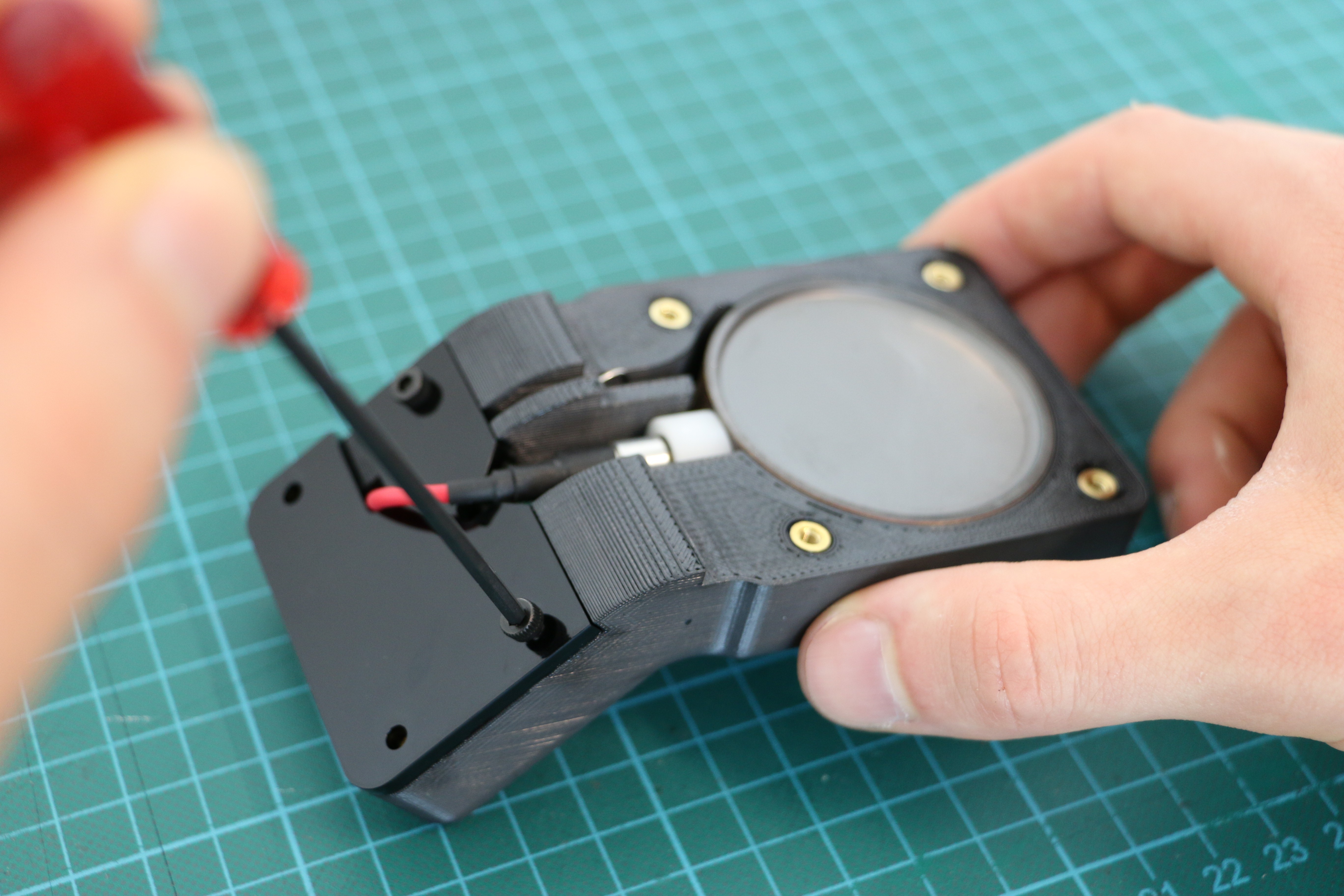
Then, insert the Gieger Tube and PCB into the case, and screw in the PCB
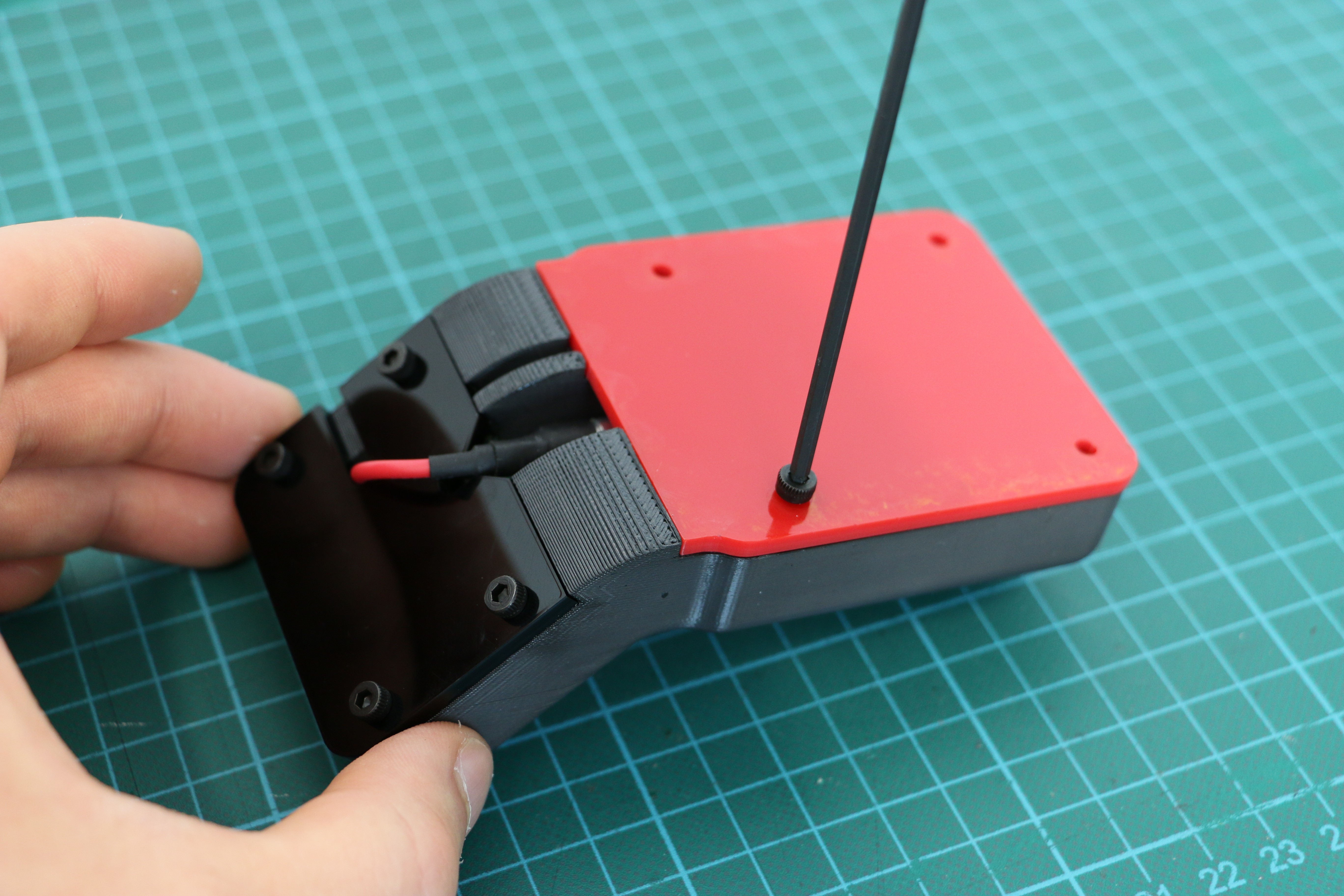
Then screw the Geiger Tube and PCB covers in place. These covers are really important as the Geiger Tube is only covered by a thin membrane, and the PCB has an exposed 500V lead!
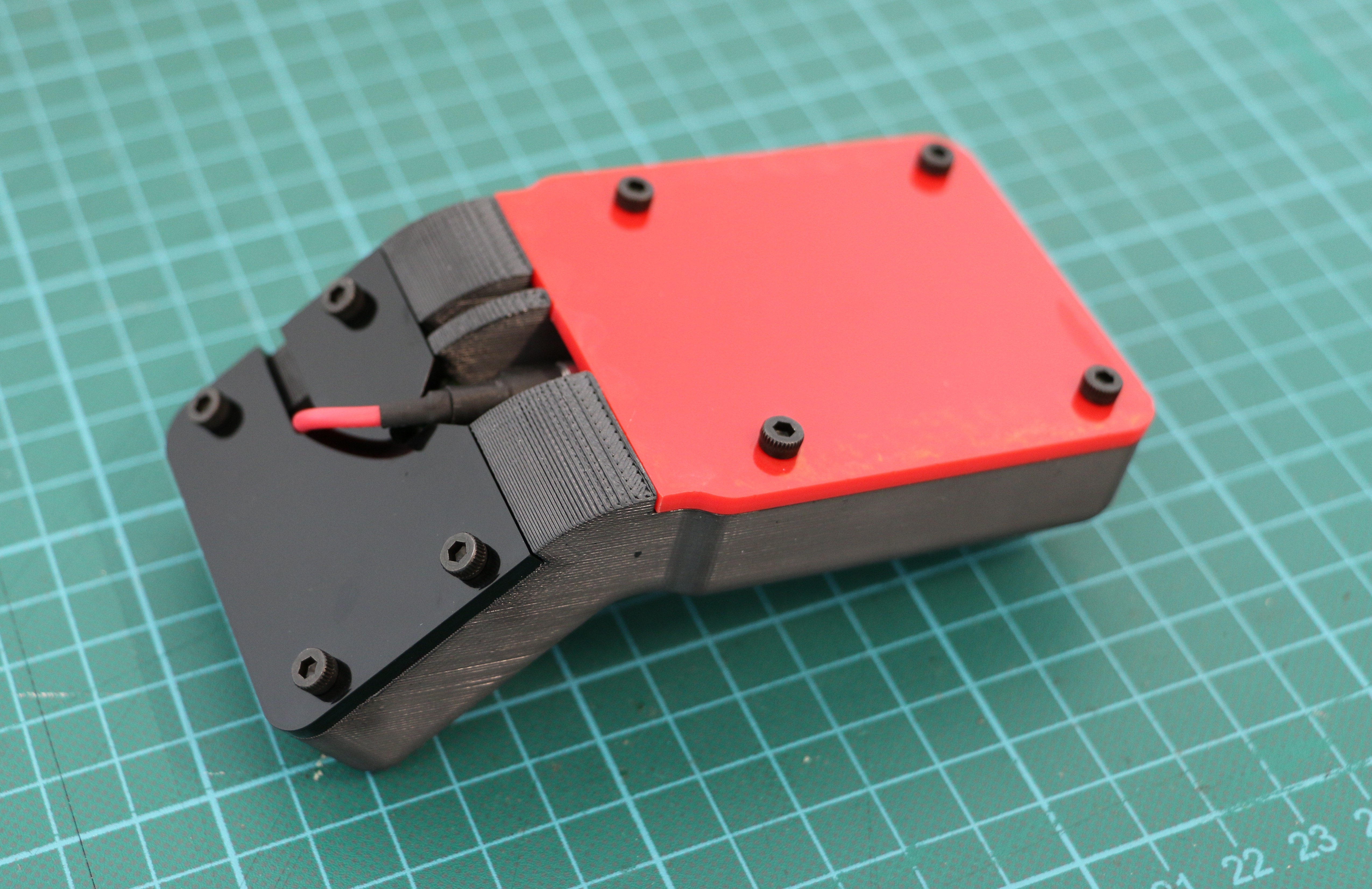
All done!
2
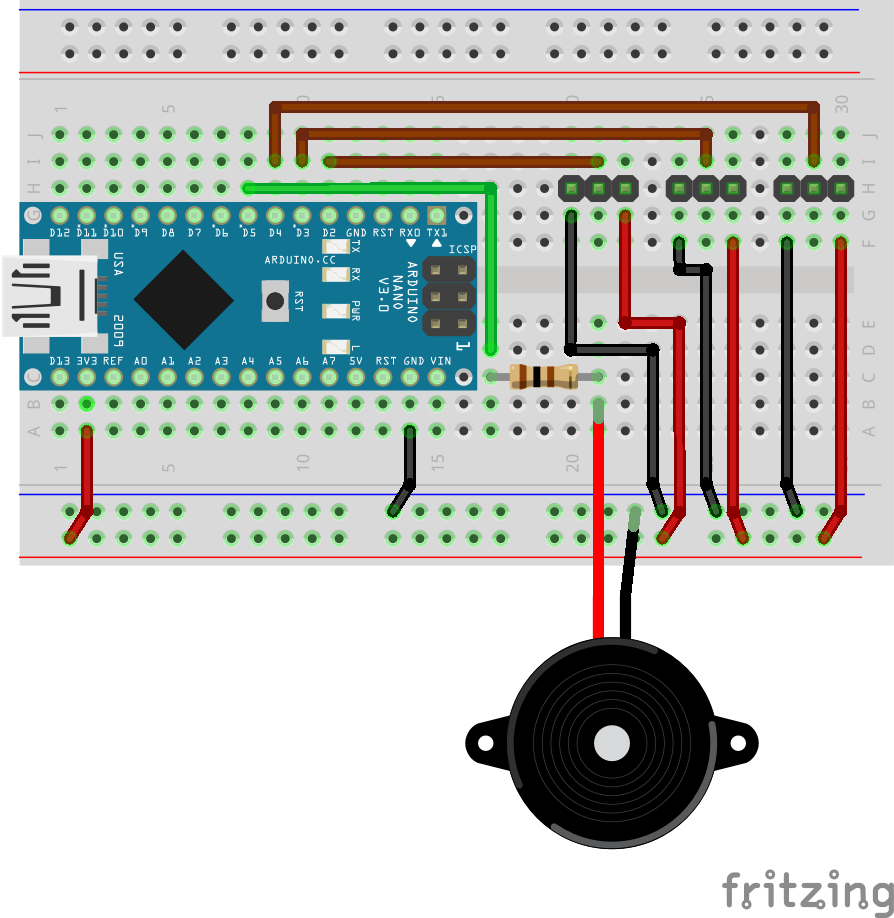
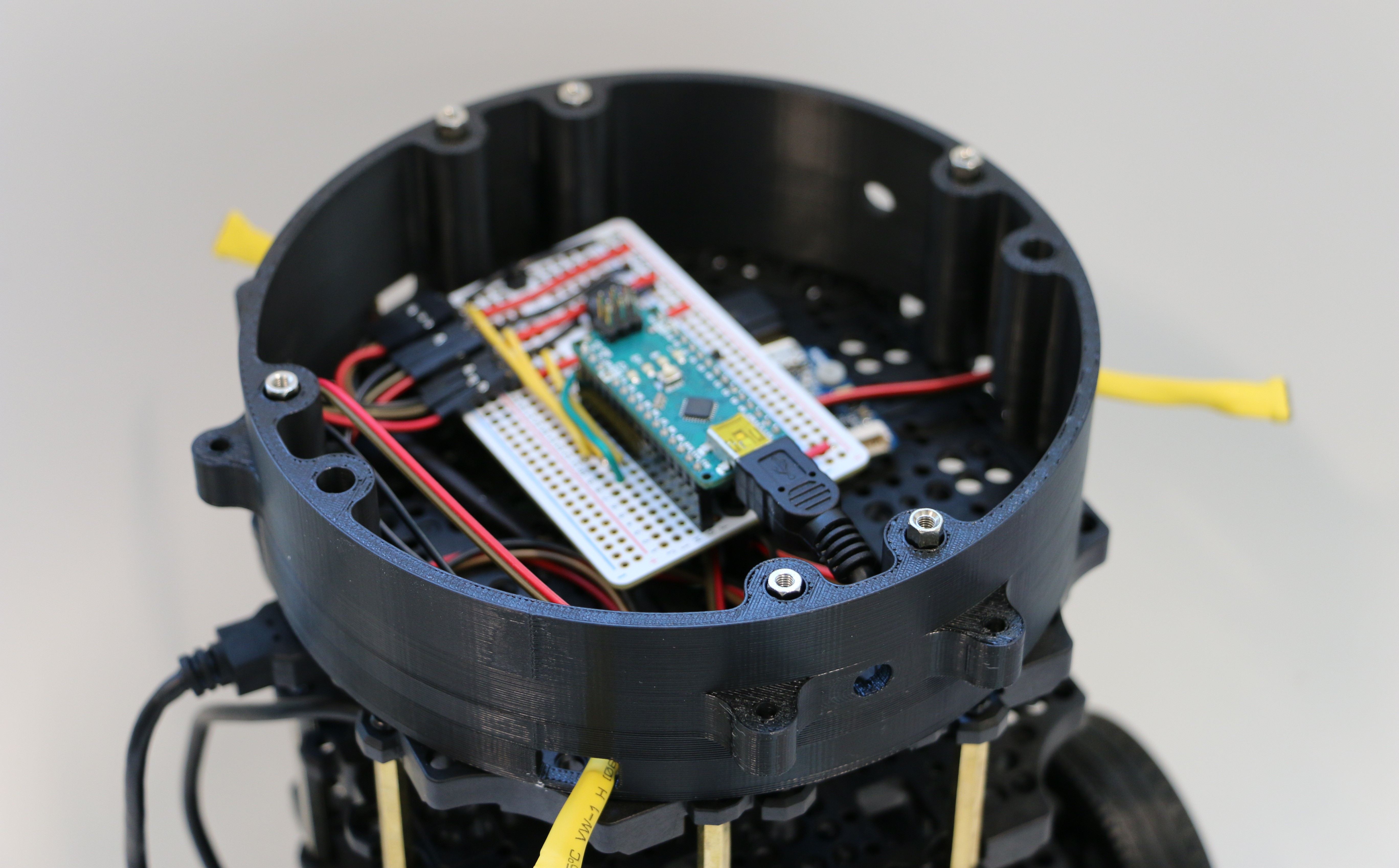
Assemble Breadboard (Protoboard) for Arduino Nano
Either on a breadboard or on a Proto board, assemble the following circuit:
(We use a protoboard and angled pin headers)
To connect the sensors, take three sets of three jumper wires (female on one side for angled pin headers), and solder "Swiss Machine Pin" female headers onto the other side. To prevent shortcuts, pack each single wire in shrink tube, also shrink a bigger tube around the header to get a stable connection.
3
Software for the Arduino Nano & ROS connection
This assumes you have ROS and the Turtlebot3 software installed on the RaspberryPi of the robot. It also assumes that roscore (ROS Master) is a laptop/additional computer. To prepare compilation of the sketch using the Arduino IDE first install the rosserial libraries for the IDE (not necessarily on the Pi - we used the ROS master laptop/computer for this):
Assuming your Arduino libraries ("sketchfolder") are stored under ~/Arduino/libraries, execute the following commands to create the libraries.
cd ~/Arduino/libraries/
rosrun rosserial_arduino make_libraries.py .
This allows now the compilation of our sketch. After flashing it onto the Arduino, connect the latter to the Raspberry Pi.
To avoid confusion with USB-serial connections, check their respective IDs on the RaspberryPi. If all (Lidar, OpenCR and Arduino) are connected, typing
No you have to find the launch files for the turtlebot package on the Pi (turtlebot3/turtlebot3_bringup/launch/turtlebot3_core.launch and turtlebot3/turtlebot3_bringup/launch/turtlebot3_lidar.launch) . They are likely located in your catkin workspace under src. You have to change the paths for the devices to what you found above. ...OpenCR... goes into the core launch file and the Silicon_Labs filename into the lidar launch file.
To start the ROS topics for the geiger counters, run:
(probably with a different ID/Filename, also from the output above).
No, a rostopic list on any rosnode (e.g. the laptop running {roscore) should show three new topics, gamma1, gamma2 and gamma3.
Ready to assemble!
4
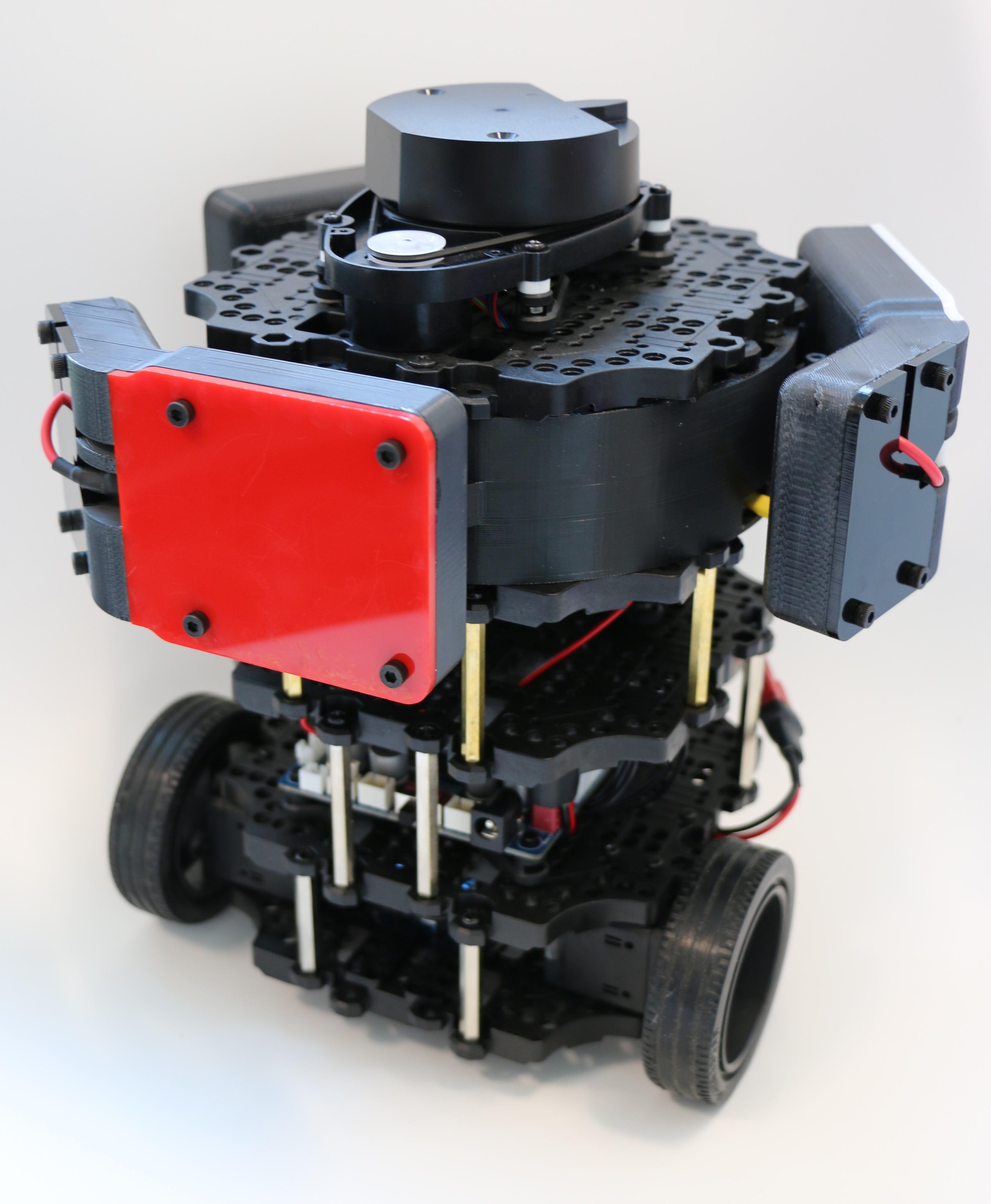
Turtlebot3 Burger Integration
For any questions regarding general Turtlebot3 Burger assembly see here. We assume here that you have a completed Burger.
First, remove the top plate with the LIDAR unit from the Burger. Install a new blank plate in its place, and put the LIDAR connection PCB on this level.
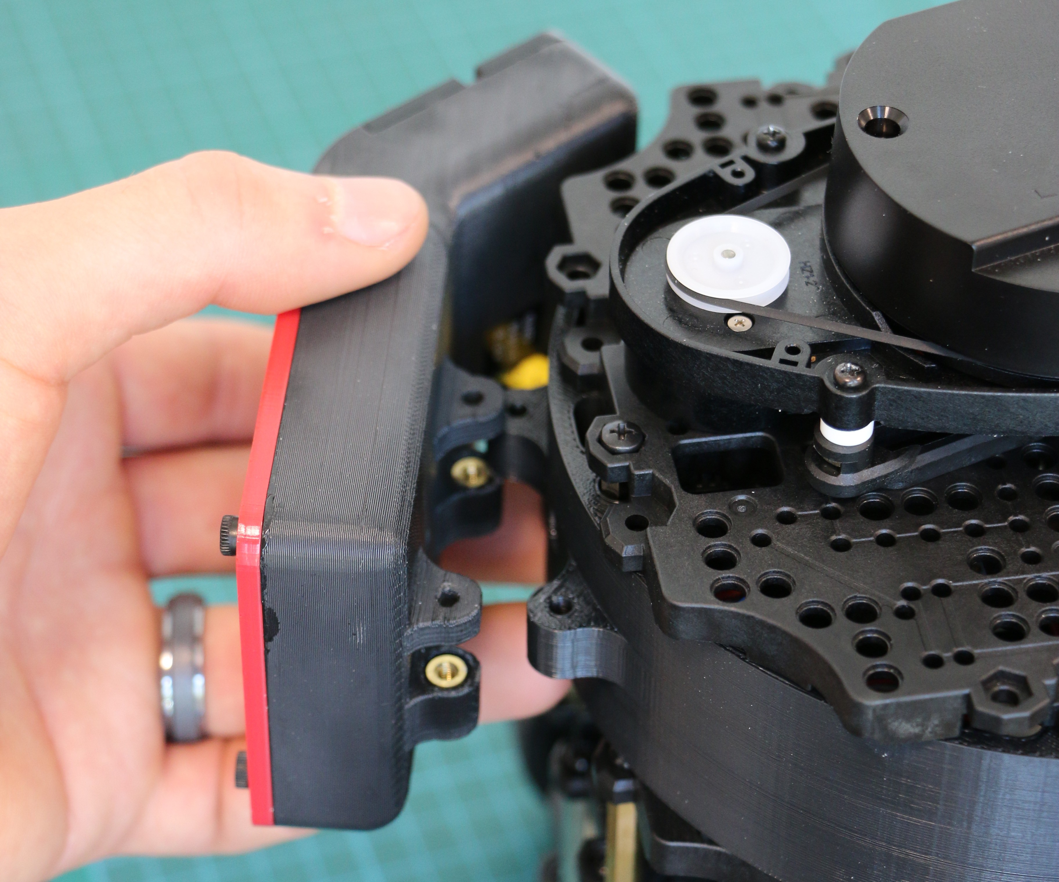
To assemble the ring on the Turtlebot3 Burger, just screw in the 20 mm M3 standoffs in the inside mounting holes on the new plate, and then slide the ring over the standoffs.
To attach the case to the ring just line up the holes, and insert and tighten two of the long M3 screws.
Then connect all the cables together (three cables from the sensors to the breadboard, the arduino to the Pi, and reconnect the LIDAR if needed). Then put the top plate back like normal.


Discussions
Become a Hackaday.io Member
Create an account to leave a comment. Already have an account? Log In.