-
Radiation Measurements: Distance Tests
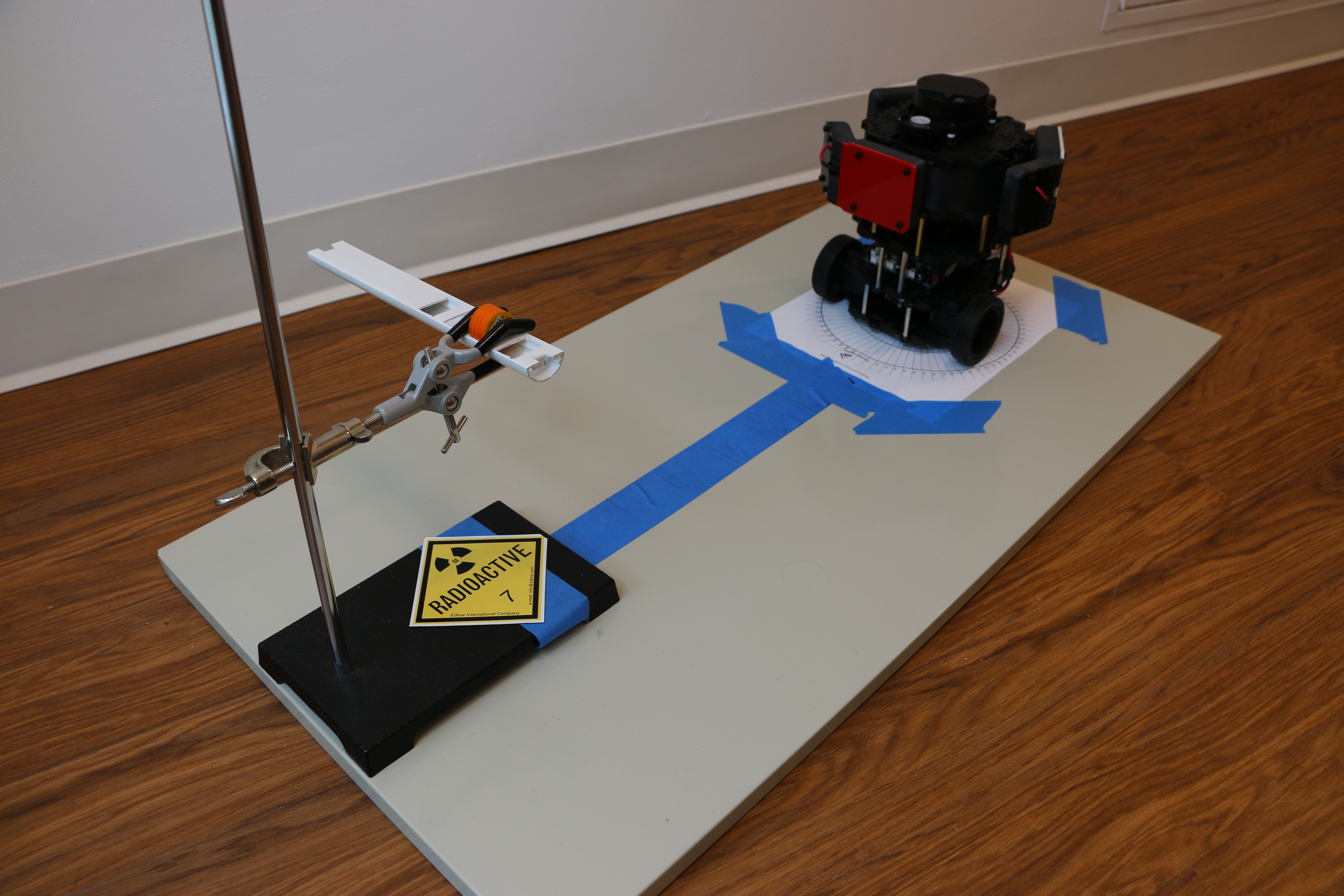
06/04/2018 at 16:14 • 0 commentsAfter we built our sensor and mounted it to the Turtlebot 3, we ran it in a stationary mode to collect some test data. We placed four small radiation test sources in a holder at the height of the sensors, and positioned the robot between 8 and 24 inches away from the sources (measured from the center of the robot). We denoted the detector facing the sources as "detector 1."
We used two Co-60 and two Cs-137 sources together. Each has an activity of about 0.5µCi (~18500 decays/second), so all-together they emit about 74000 gamma particles per second in all directions. While this sounds a lot, the sources are actually relatively weak and are meant to be used for educational purposes.
![]()
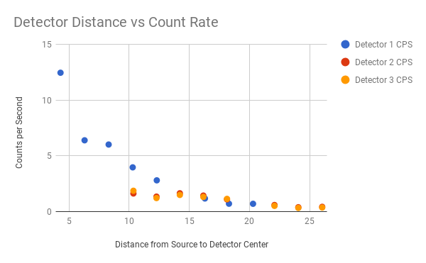
The detection rates are much smaller mainly due to two reasons. First, the area of the detector is small compared to the area where particles could be (surface of a sphere with sources at center and radius equal to distance of detectors to sources). Second, the detectors have a very low efficiency, so not every gamma photon crossing a detector is actually detected. Another reducing effect, absorption of the radiation in air, is relatively small compared to the first two.
![]()
In the figure above, you can see that the count rate decreases with the square of the distance to the sources. At each distance, we measured for about 10 minutes, and the distance listed is the distance from the source to the center of the detector. The count rates for the two detectors further away are smaller because they expose a smaller detection area to the source. The figure also shows a limitation of our robot - not much more than two feet away from the sources (at the given activity levels), the signal will be hard to impossible to distinguish from the background. So a scanning robot will have to get close!
Based on these measurements, we will now go on and combine radiation measurements with mapping of the room based on the LIDAR sensor and a SLAM algorithm.
-
Radiation Counting - Ready for ROS
05/22/2018 at 19:19 • 0 commentsAfter we got a single radiation detectors to work with an Arduino Nano, the next step was to connect three of them to the board and write a sketch that provides the data as ROS topics using the rosserial package.
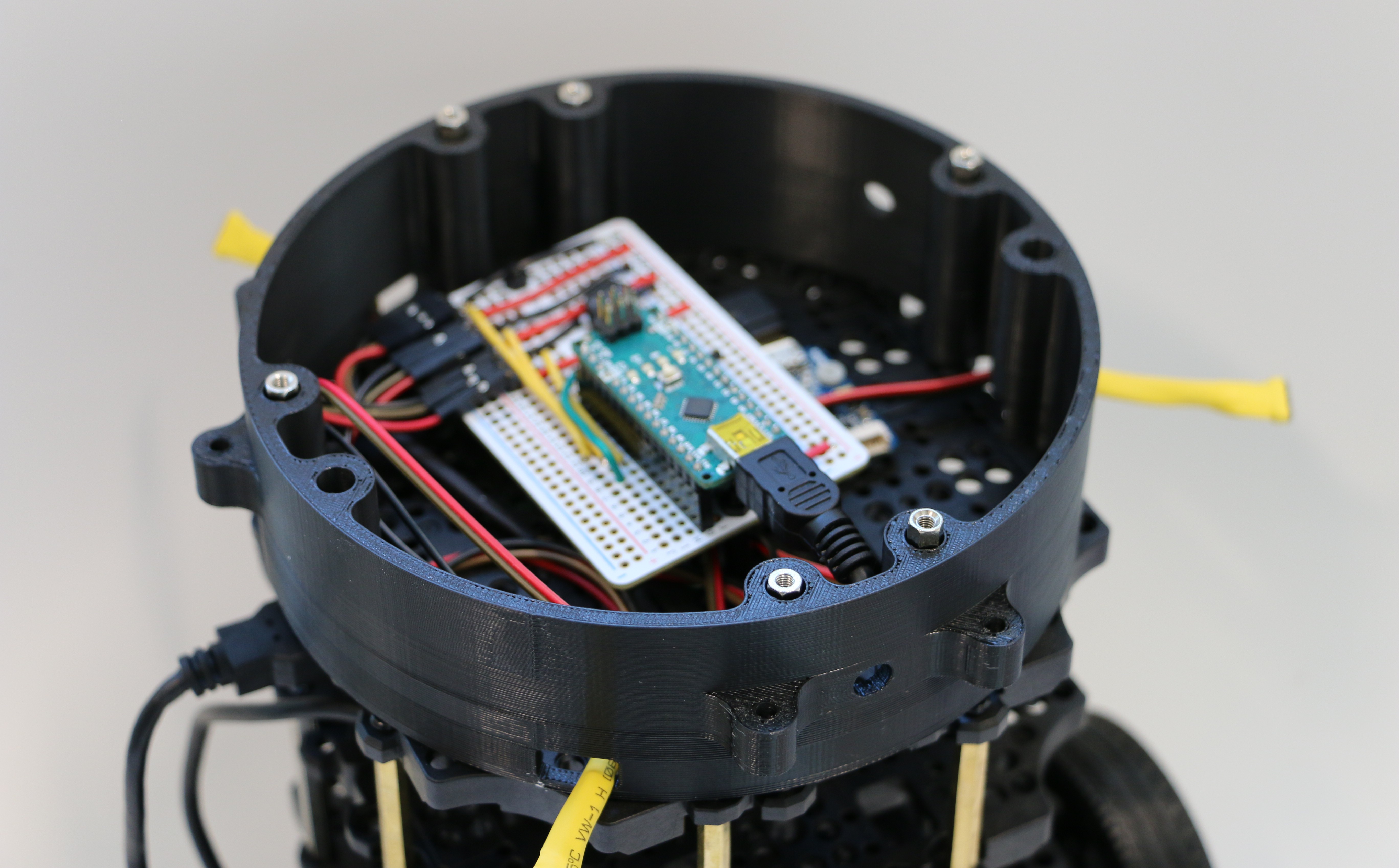
Instead of using a breadboard to connect the Arduino Nano to the detectors (and the little buzzer, see previous logs), we decided to solder it onto a half-size proto board. This makes most connections somewhat more reliable. The cables to the detectors where connected using angled pin headers.
![]()
The Arduino runs this sketch. Same as for one detector, but now with three. And with the ability to provide ROS topics. To compile the sketch, it is necessary to install the rosserial libraries for the Arduino IDE. The package provides an include file that has to be used in the sketch.
As the Nano does not have a direct connection to the ROS network, it is necessary to run an additional bridging node. For our setup, the Nano is connected via USB to the RaspberryPi of the Turtlebot3. The bridge is provided by `rosserial_python` command. Here is a small drawing possibly helping the explanation:
+---------------------------+        +---------------------------+         +---------------------------+
|                           |        |                           |         |                           |
|        `rosserial`        | Serial |    `rosserial_python`     | Network |         `roscore`         |
|      on Arduino Nano      +-------->      on RaspberryPi       +--------->         on Laptop         |
| collecting radiation data |  over  |  bridging serial to wifi  | (WiFi)  |   providing ROS master    |
|                           |  USB   |                           |         |                           |
+---------------------------+        +---------------------------+         +---------------------------+
After we compiled and loaded the sketch on the Arduino Nano, and started the bridge node on the RasberryPi, three new ROS topics became available - gamma1, gamma2 and gamma3 for the three detectors. The topics only provide output whenever one respective detector detects an event, the output is the time since the startup of the Arduino Nano in micro seconds.
It all worked well, until we started to put the other parts of the Turtlebot 3 back together. Suddenly, we ran into problems with the serial bridge. Of course - the situation is more complex than depicted in the drawing above. The Turtlebot 3 is run by OpenCR, a control module made by Robotis. It also connects to ROS over a serial/USB connection via the RasbperryPi (not shown in drawing above).
On various reboots, we figured that the USB serial devices switched the enumeration of /dev/ttyUSBx for both devices, which confused the Turtlebot Launch files. To avoid this to happen, we resorted to using the entries in /dev/serial/by-id/ for all relevant commands. For example to launch the serial bridge for the Arduino Nano:
rosrun rosserial_python serial_node.py /dev/serial/by-id/usb-FTDI_FT232R_USB_UART_AH06N8i02-if00-port0
instead of
rosrun rosserial_python serial_node.py /dev/ttyUSB1
We also needed to change launch files of the Turtlebot 3 repository to the respective filenames. This included the file 'turtlebot3/turtlebot3_bringup/launch/turtlebot3_core.launch', and also the file 'turtlebot3/turtlebot3_bringup/launch/turtlebot3_lidar.launch' as the LIDAR also has a USB-Serial connection. The actual /dev/serial/by-id/ filenames are easy to find out - just unplug every other device except one. After doing this, we were ready to go, and all USB-Serial connections could be found after rebooting.
-
Turtlebot3 Burger Integration
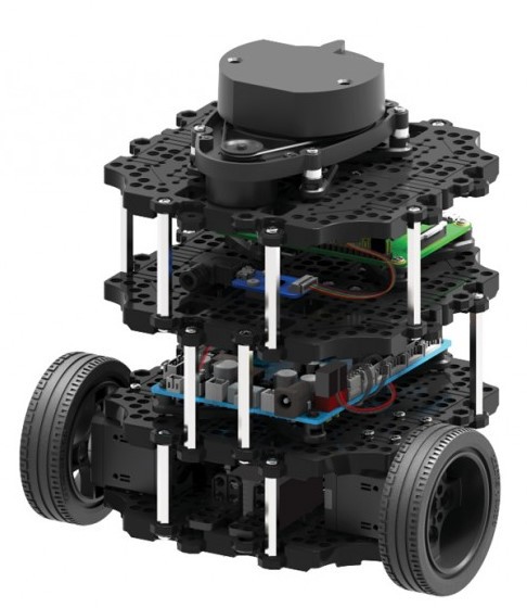
05/22/2018 at 05:03 • 0 commentsWith the sensor case and electronics complete it’s time to put our sensors on a real robot and unleash it into the wild! We’ll be using a Turtlebot3 Burger from Robotis because it’s one of the most popular educational robotics platforms and we already have one handy. We decided to mount three sensors on our Burger to enable better sensitivity.
![]()
The Burger is conveniently built as a series of “plates,” with each plate comprising a level that holds electronics/motors/sensors. We’ll just be adding a level to the Burger that holds three of our radiation sensors, along with an arduino to interface with the onboard Raspberry Pi via ROS.
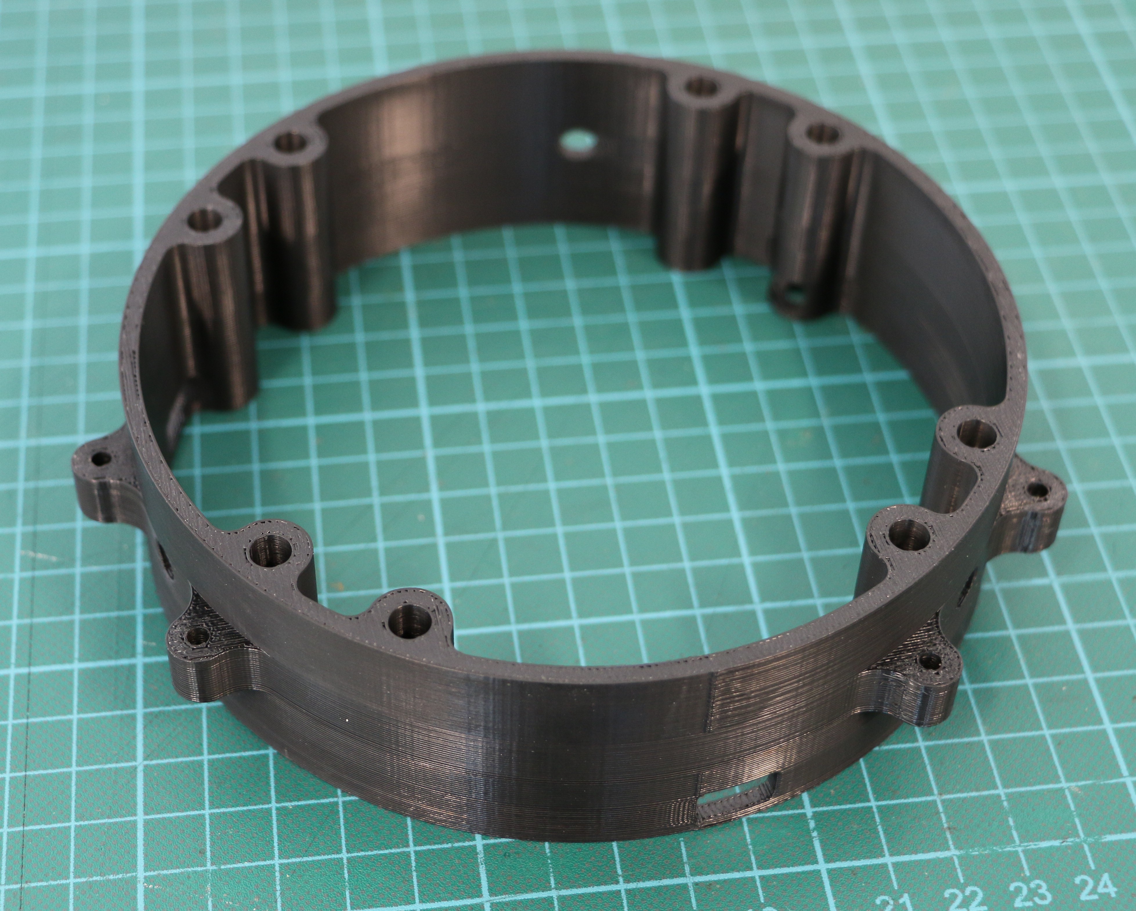
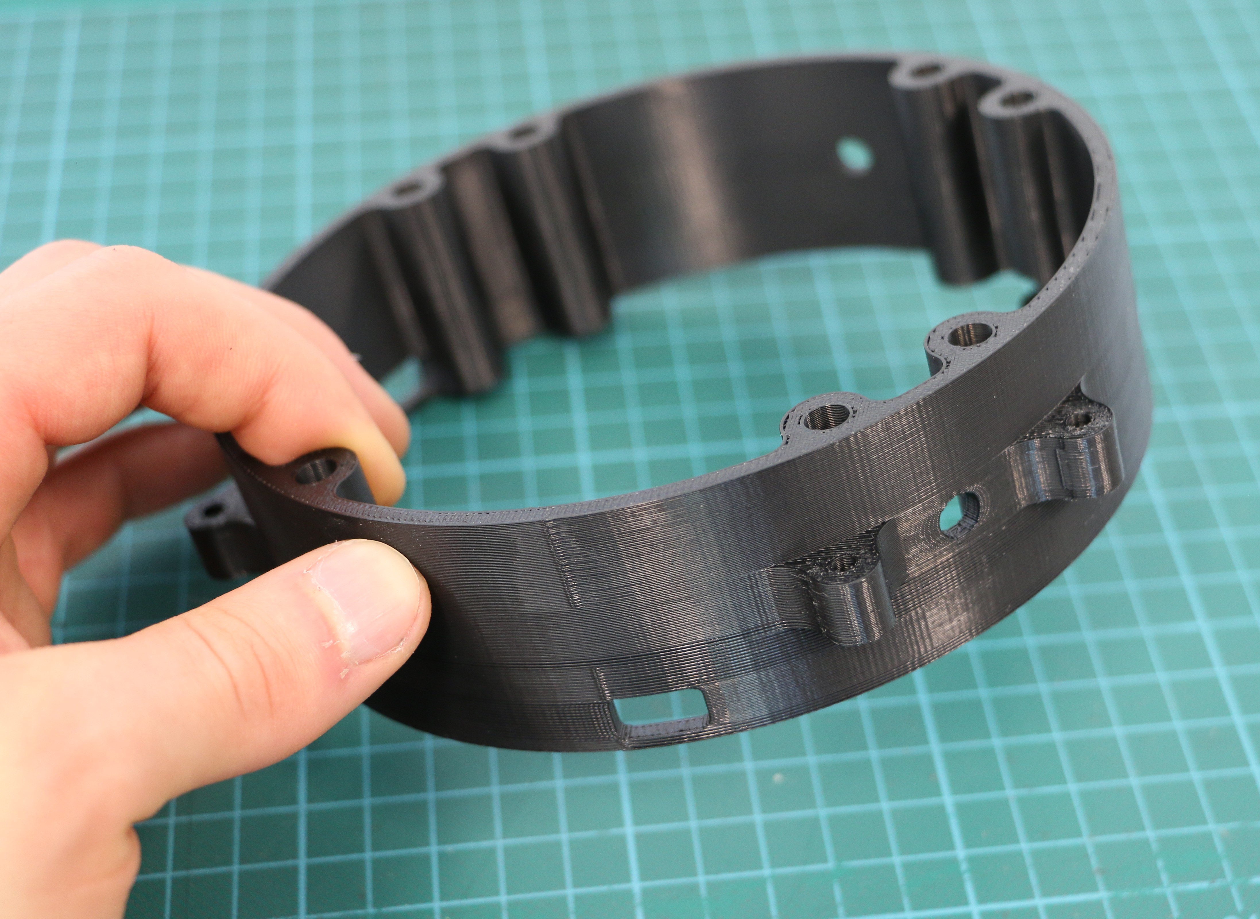
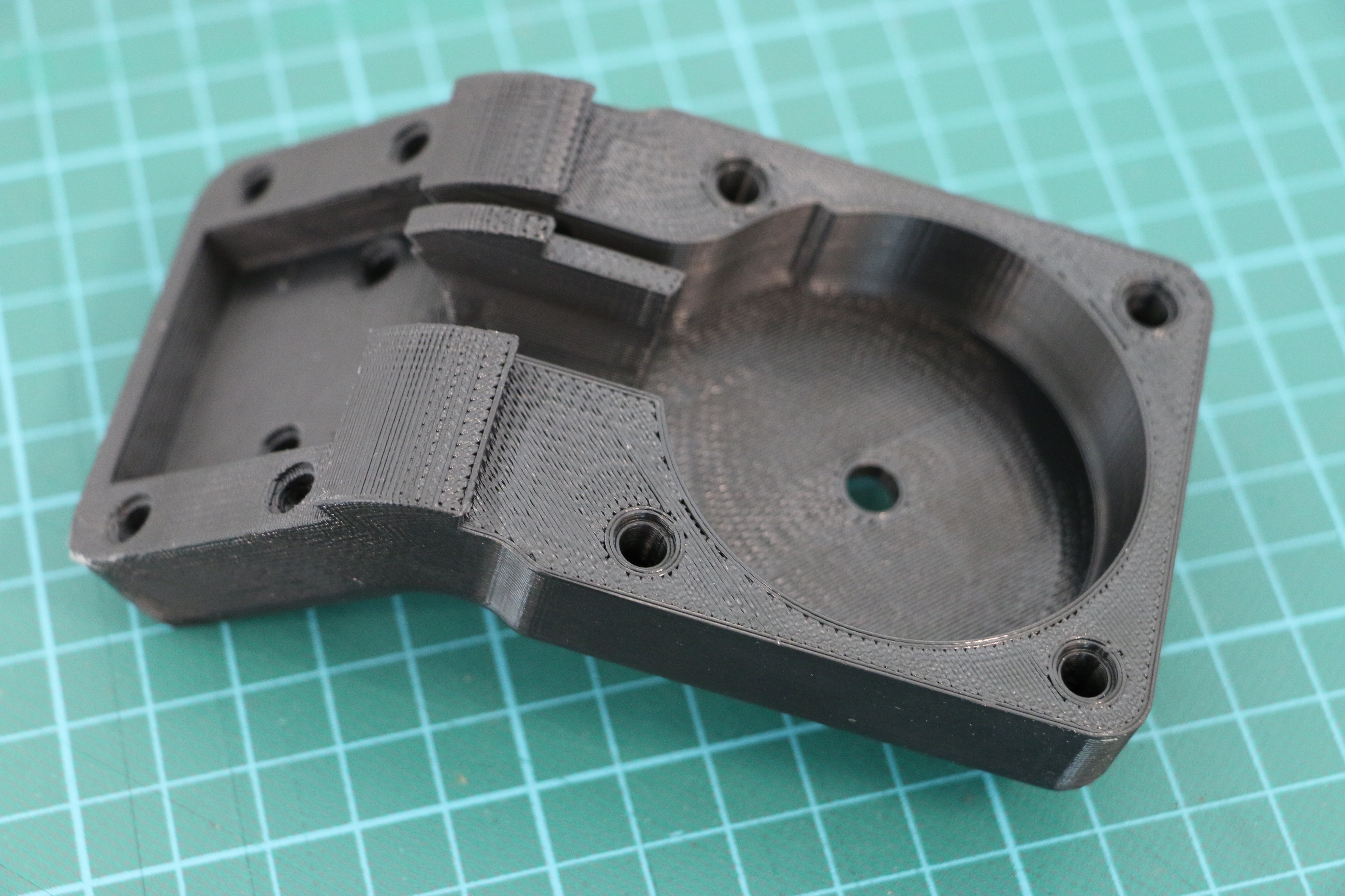
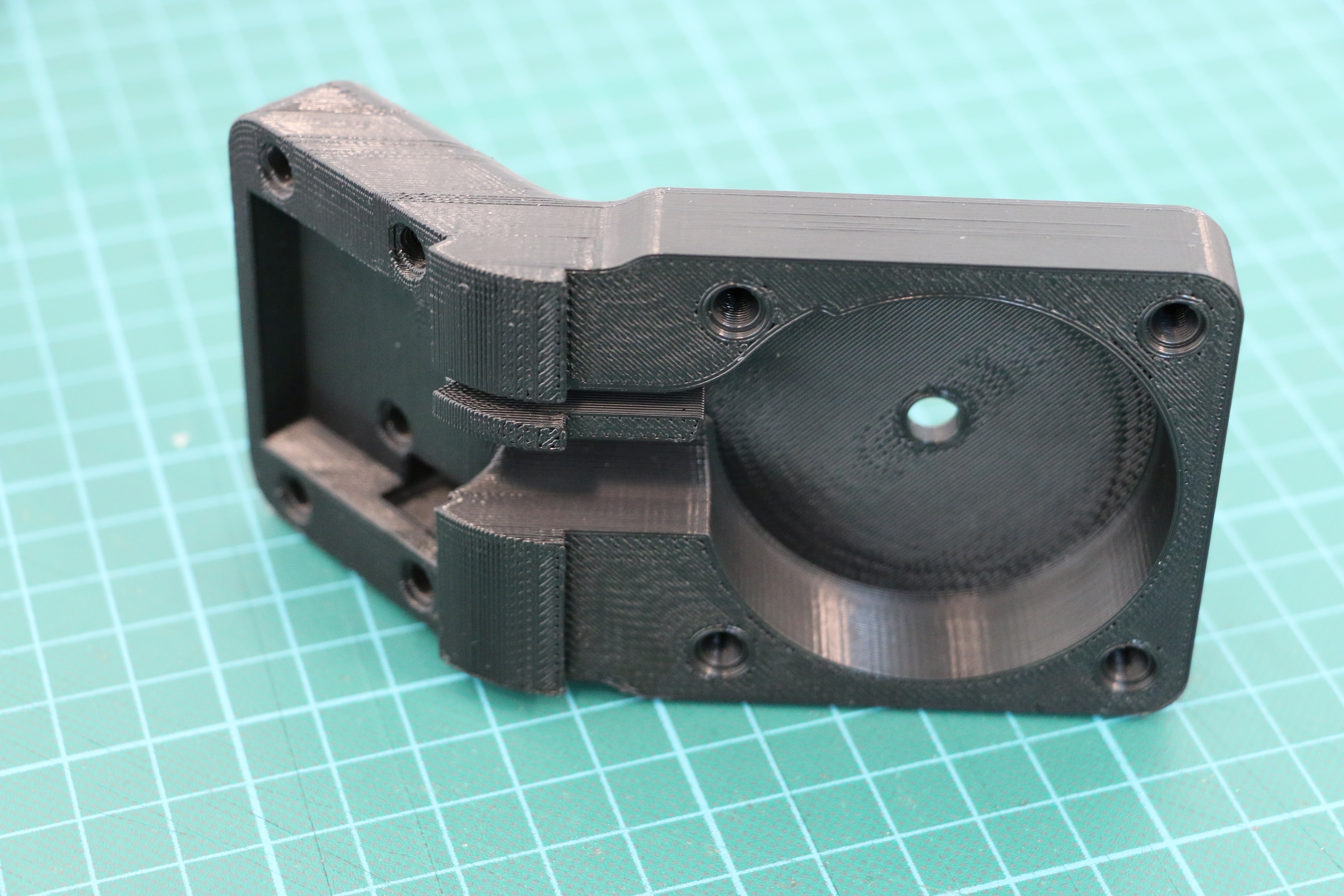
To enable simple sensor mounting, we 3D printed a ring that interfaces with the holes on the Burger and has attachment points for the sensor case mounts.
![]()
![]()
Fortunately the ring turned out well on the first try, so we put it on the Turtlebot3, connected everything with the arduino inside, and put the top plate back on. See the instructions for more details on this assembly process.
-
Sensor Casing Prints and Assembly
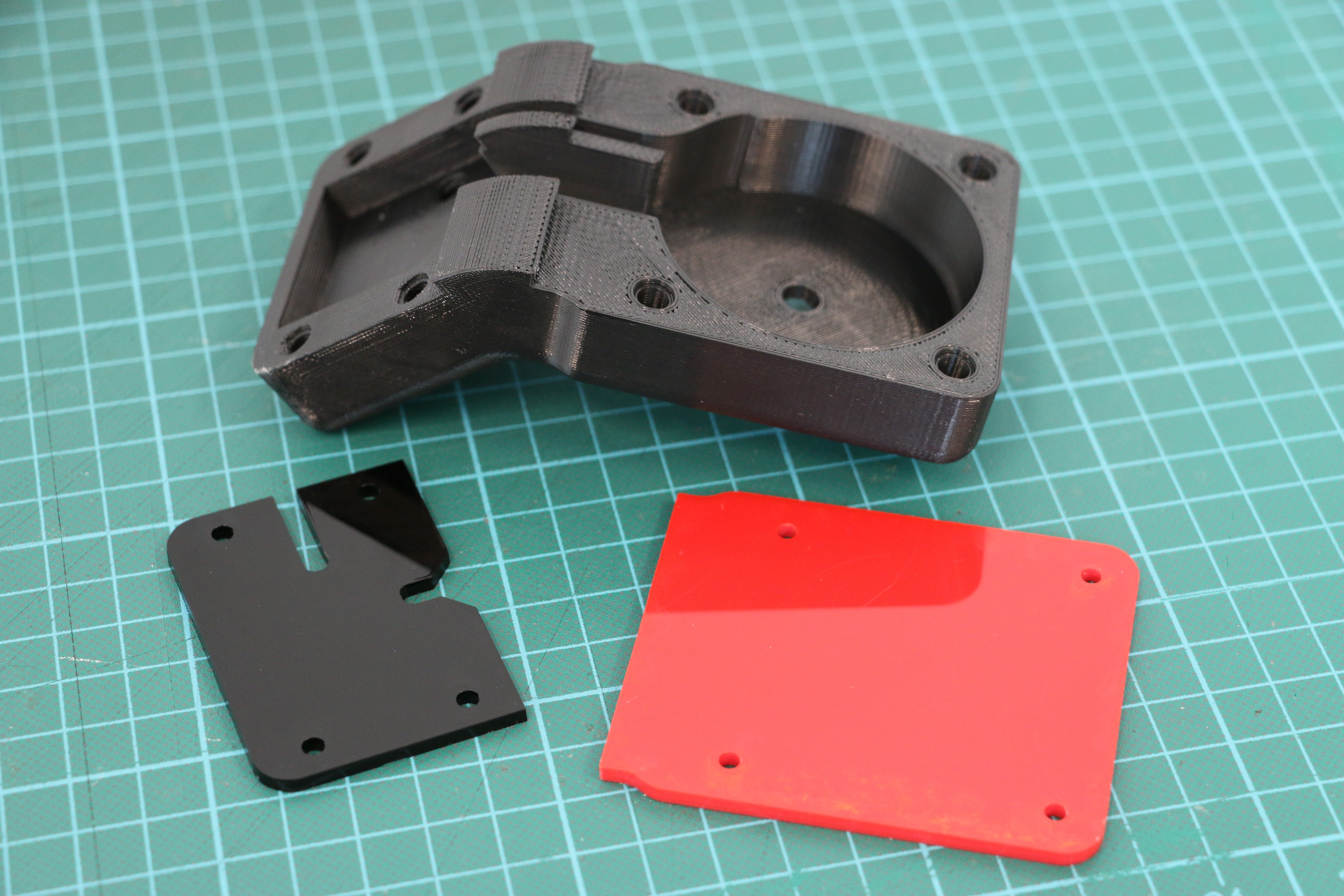
05/21/2018 at 04:00 • 0 commentsNow that the sensor casing design is finalized it’s time to print two more to complete our three-sensor setup for the turtlebot3. Each case also needs heatset inserts and covers. Our covers are lasercut from acyrlic, but can be 3D printed if need be. For assembly instructions see the instructions page.
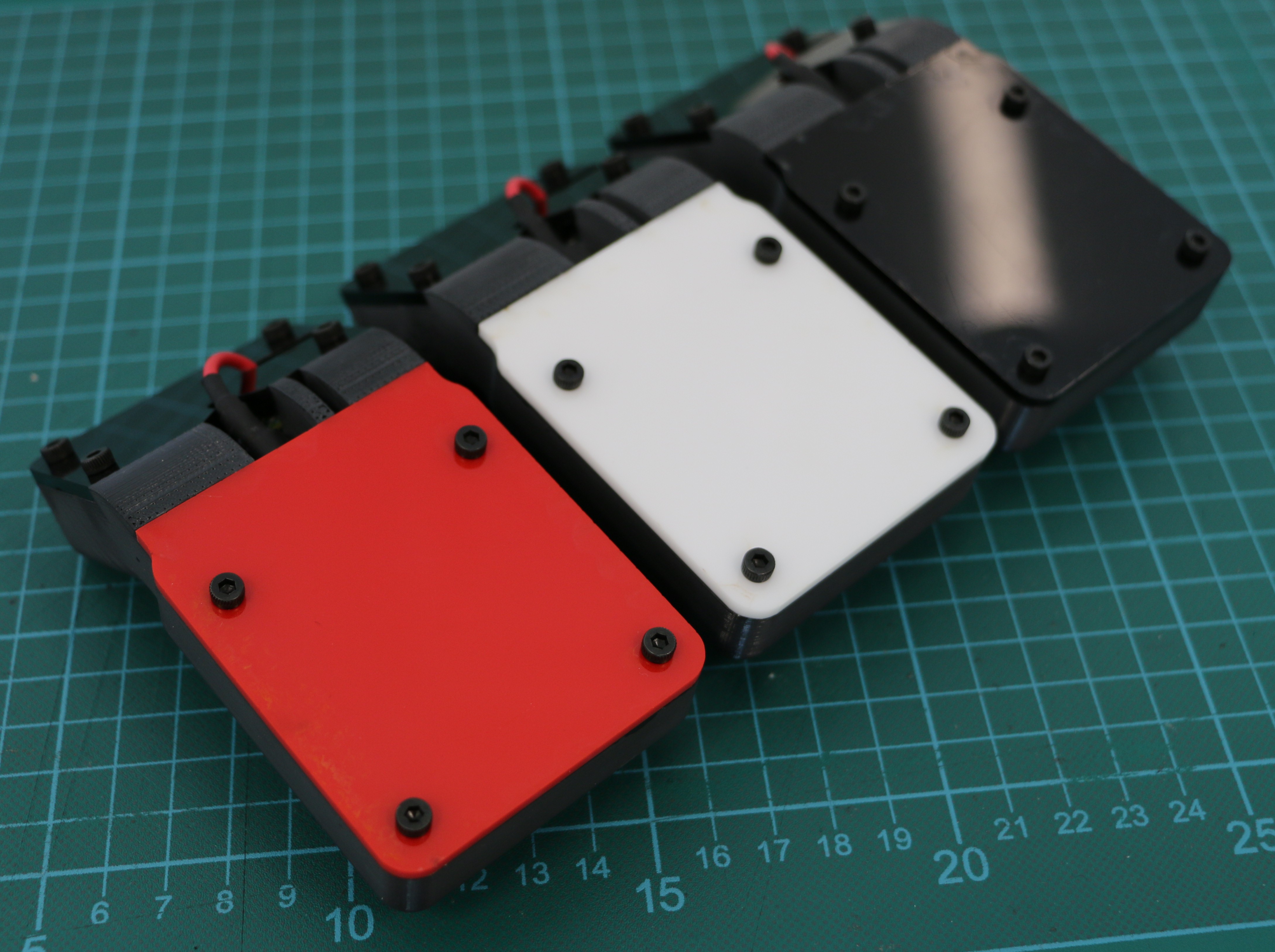
Here is one case with covers before assembly:
![]()
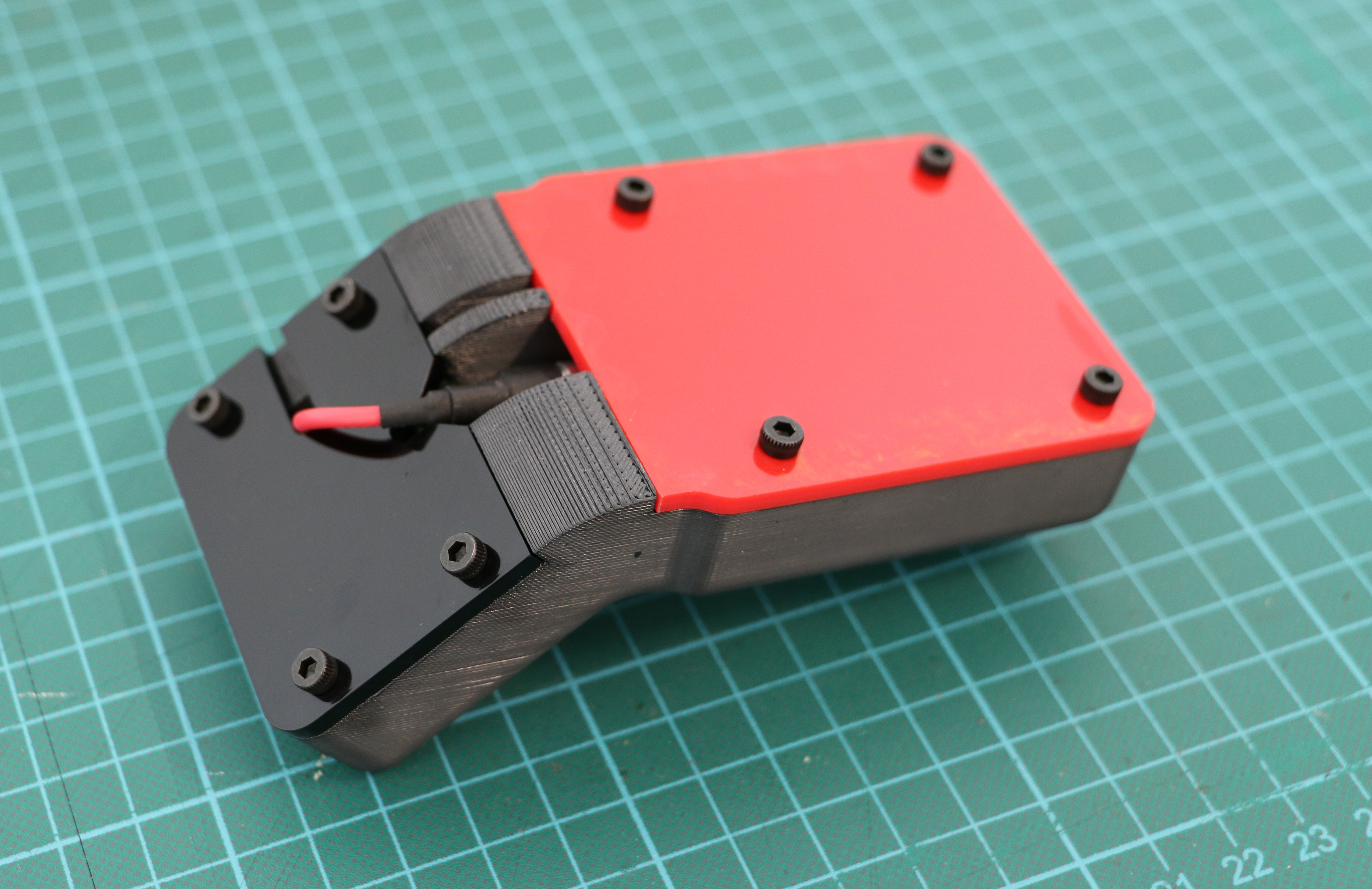
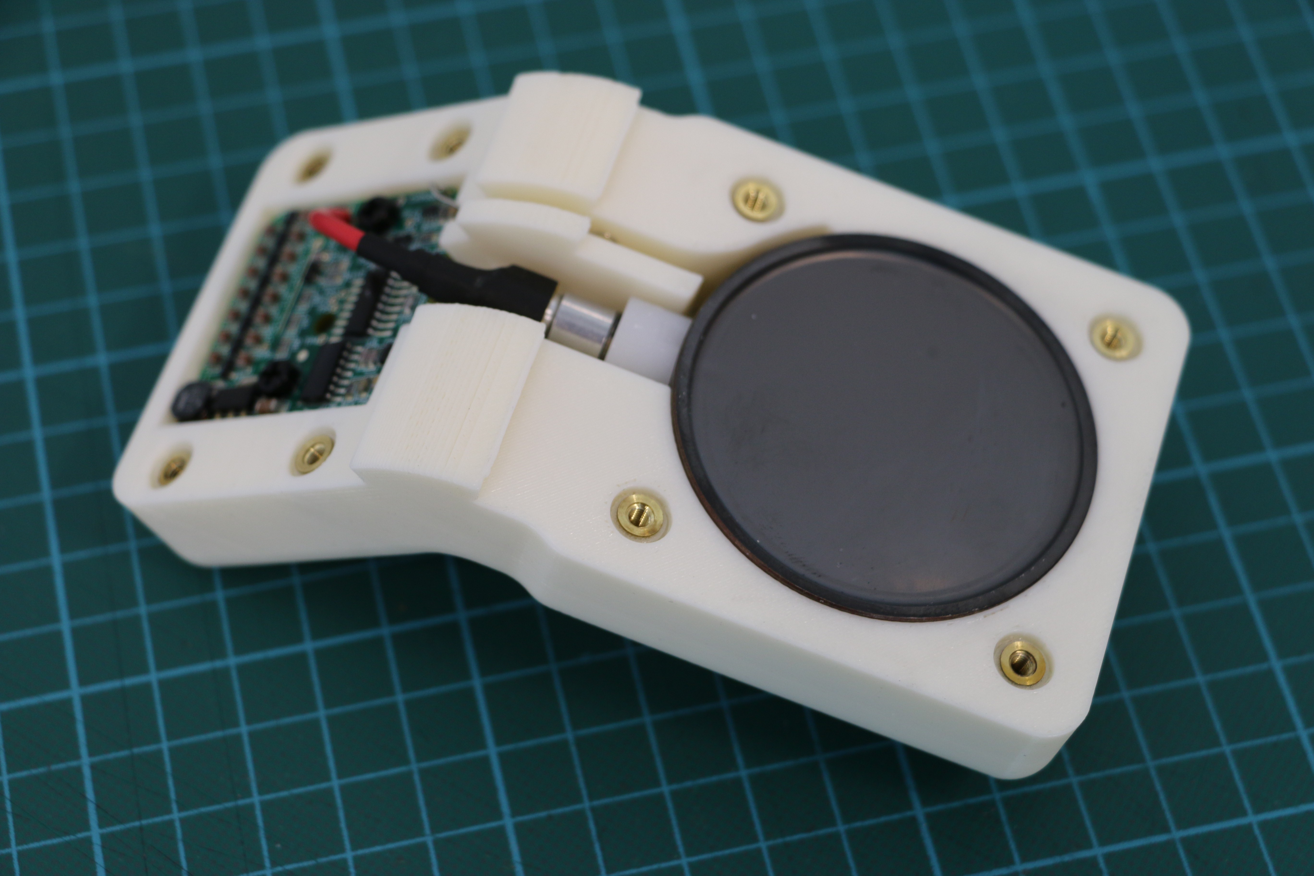
Here is one case/sensor full assembled:
![]()
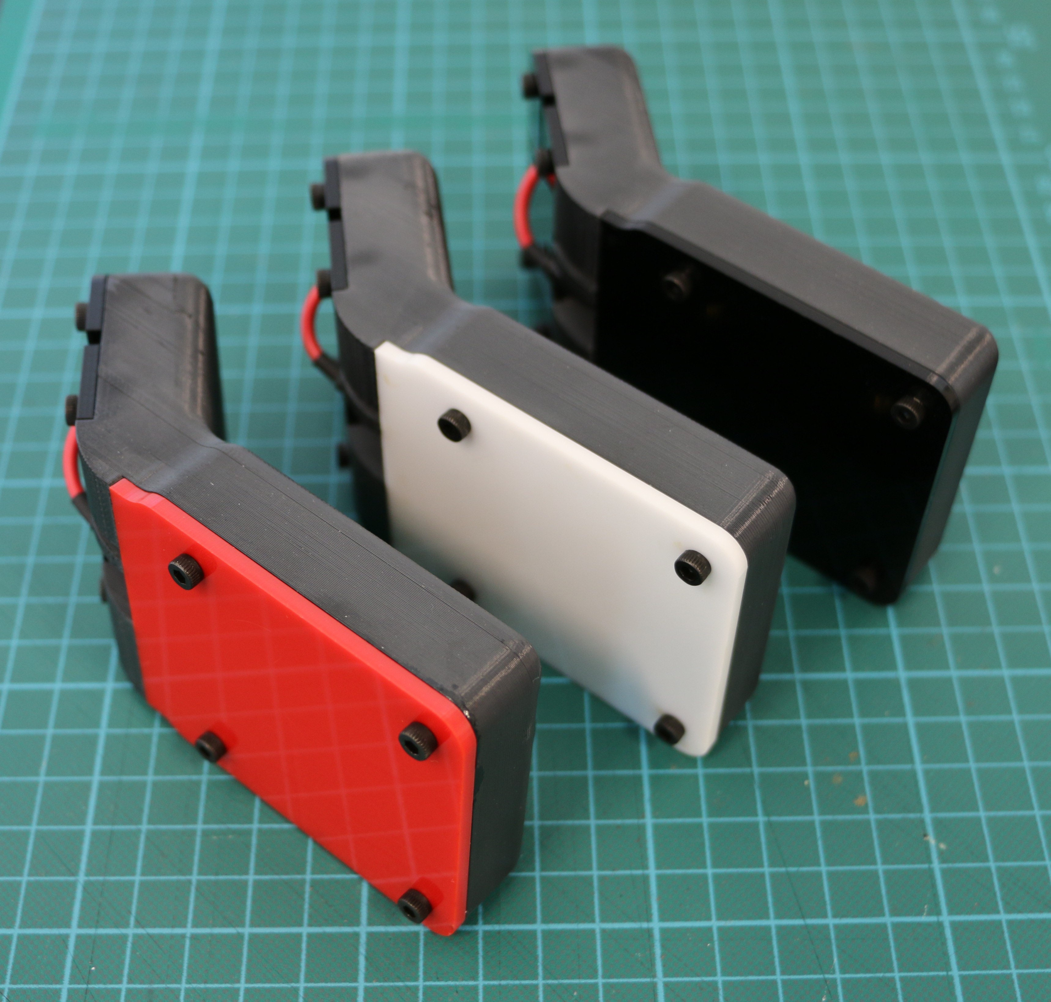
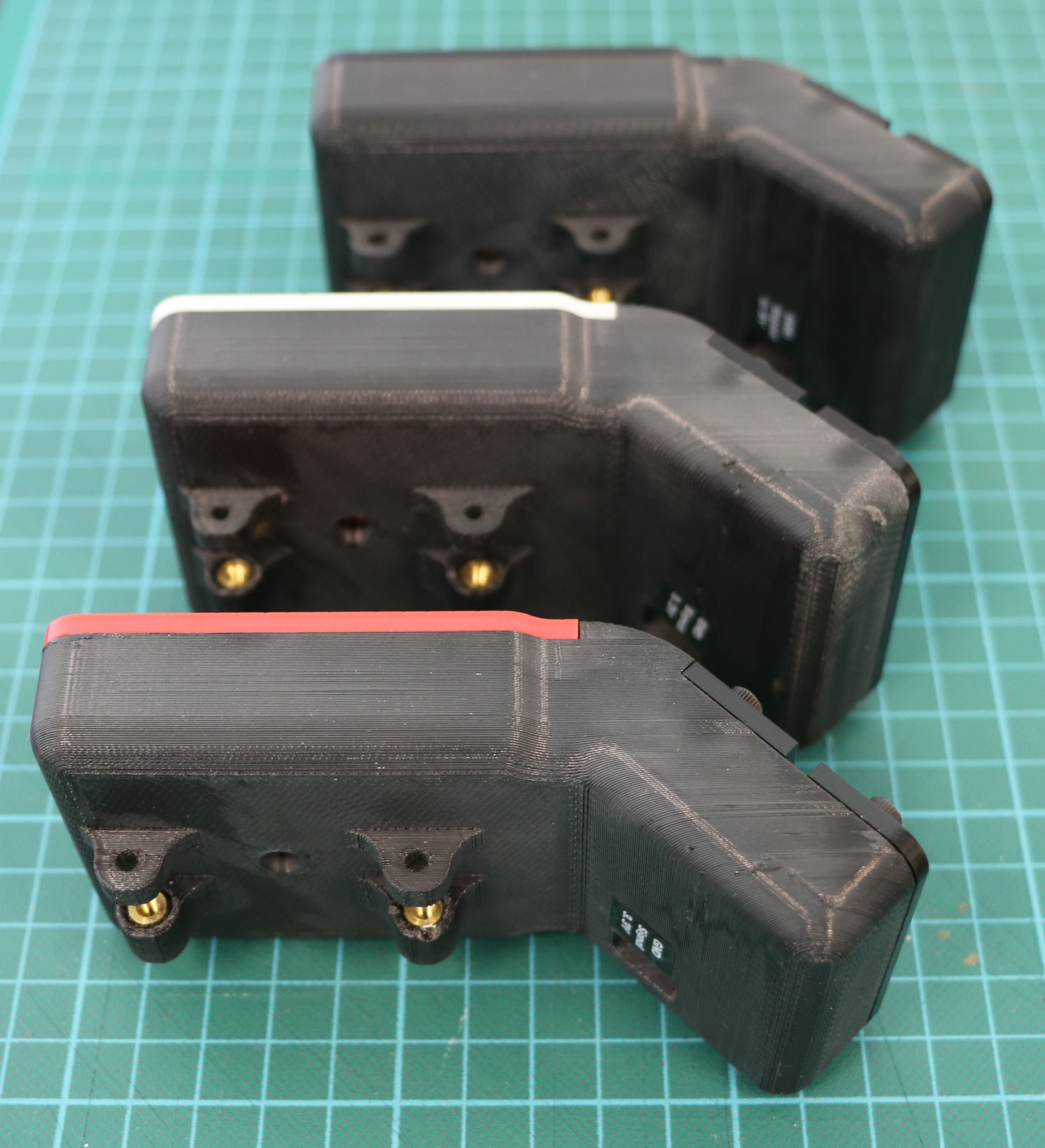
Here are the three assembled sensors in their cases with covers:
![]()
![]()
![]()
The case is designed to mount on a robot using long (20 mm) M3 screws via two holes spaced 40 mm apart. This will allow easy connections with robot projects. In the coming weeks we’ll be mounting the sensor on a Turtlebot3 Burger, so stay tuned!
-
First radiation counting
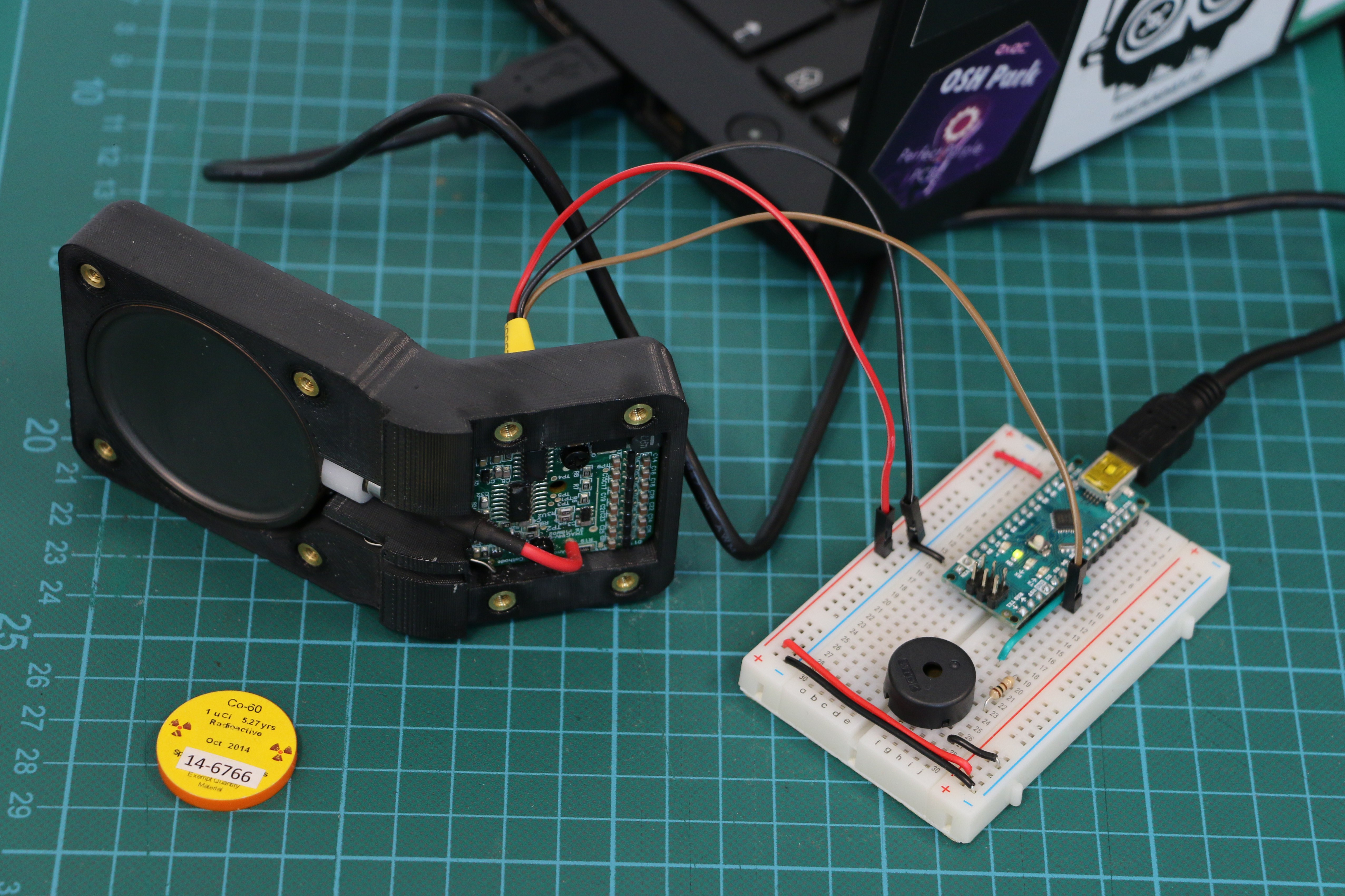
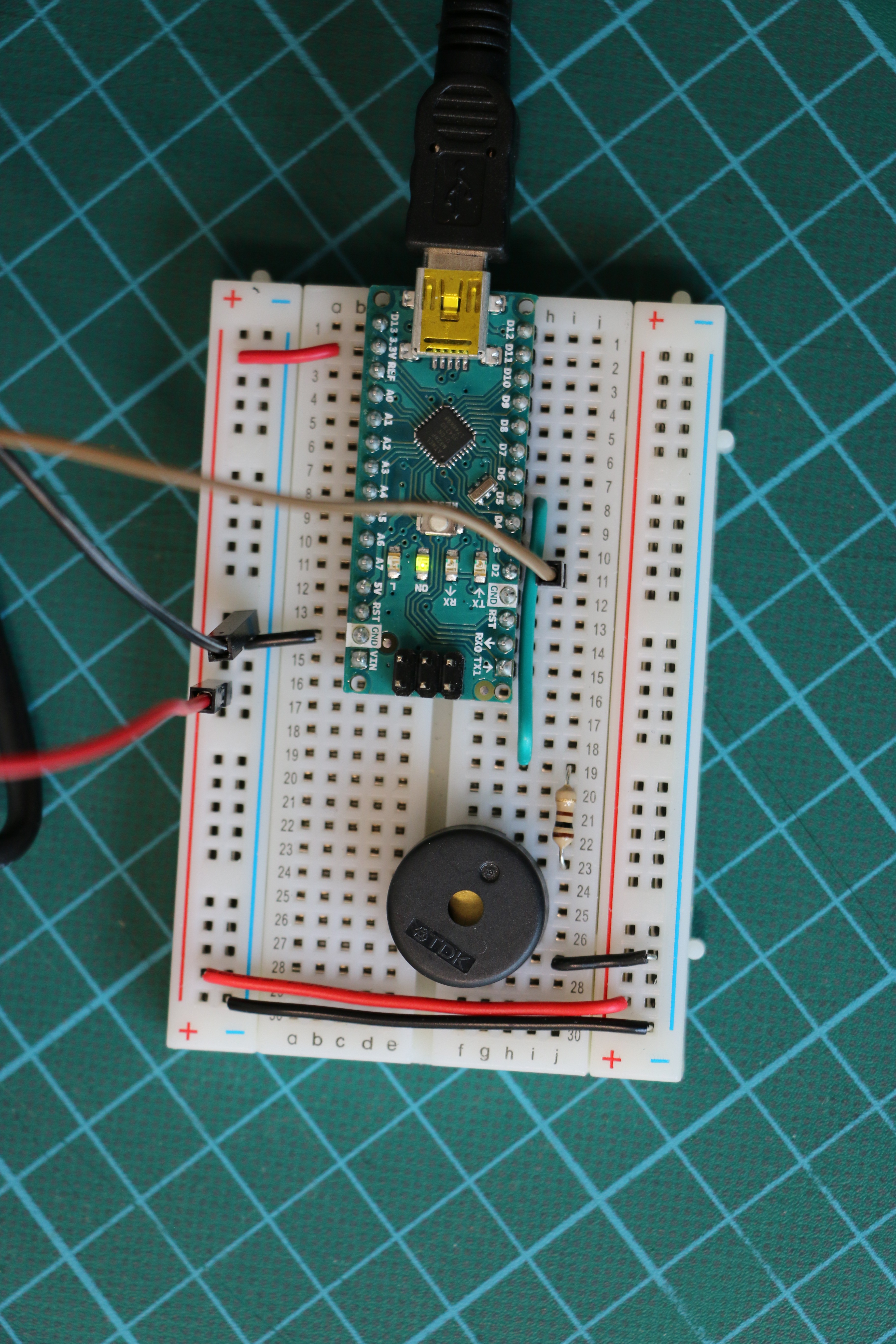
05/17/2018 at 22:17 • 0 commentsBefore connecting three detectors to the Arduino Nano, we made sure that one would work. Using the iRover HV Board/signal processor, connection is simple. The HV board uses 3.3V supply voltage to provide 500V for the Geiger-Mueller tube. It also does some basic signal processing, and outputs a clearly defined pulse (approx. 130µs long) per detected event. The output can directly be read at one of the digital input pins of the Nano.
The iRover HV Board has a header with three pins. It is not the same header as used on the Arduino or other boards, but ones that go under the name "Swiss Machine Pin" (or similar names like "swiss round machined pins" etc.). We simply solder three female headers to male jumper wires and stabilized it with shrink tube.
![]()
We added a small buzzer to the circuit that clicks for every event. This was very helpful for debugging - the closer you bring a test source, the higher the click rate. If you can't hear clicks, probably something is wrong, e.g. a loose cable. The buzzer is also driven by a digital I/O pin, with a 100 Ohm resistor between pin and buzzer to limit the current it can draw from the pin.
![]()
The code for this setup has not yet ROS compatibility, but just displays events on the serial output and clicks when an event happens. Here is the sketch:
#define DETECTIONDELAY 140  // in micro seconds

const int detectorPin = 2;
const int buzzerPin = 5;
unsigned long nextEvent = 0;

void setup() {
  Serial.begin(115200);
  delay(2000);
  Serial.println("GeigerROS");

  pinMode(detectorPin, INPUT);
  nextEvent = micros() + DETECTIONDELAY;
}

void loop(){
  if (digitalRead(detectorPin) == HIGH) {
    if(micros() > nextEvent) {
      nextEvent = micros() + DETECTIONDELAY;
      tone(buzzerPin, 1000, 2);
      Serial.print(micros());
      Serial.println(" µs: Event detected");
    }
  }
}
After we check if the input pin is 'high' we check if enough time has passed since the last event. We know that the pulses remain 'high' for about 130µs. So we just set a delay of 140µs to be on the safe side. The clicks are produced using the 'tone' function of the Arduino library.
-
Sensor Casing Design Version 1.1
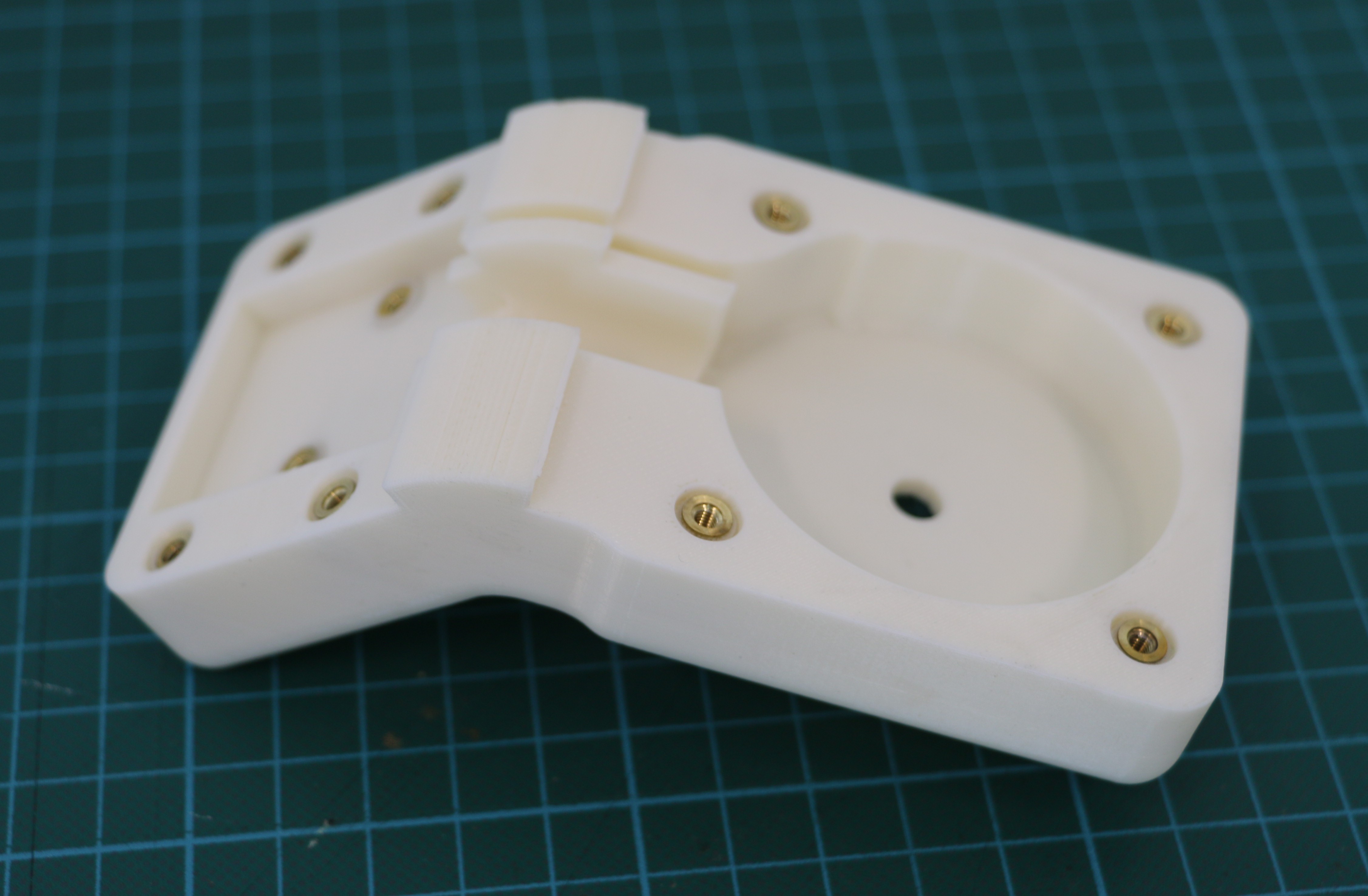
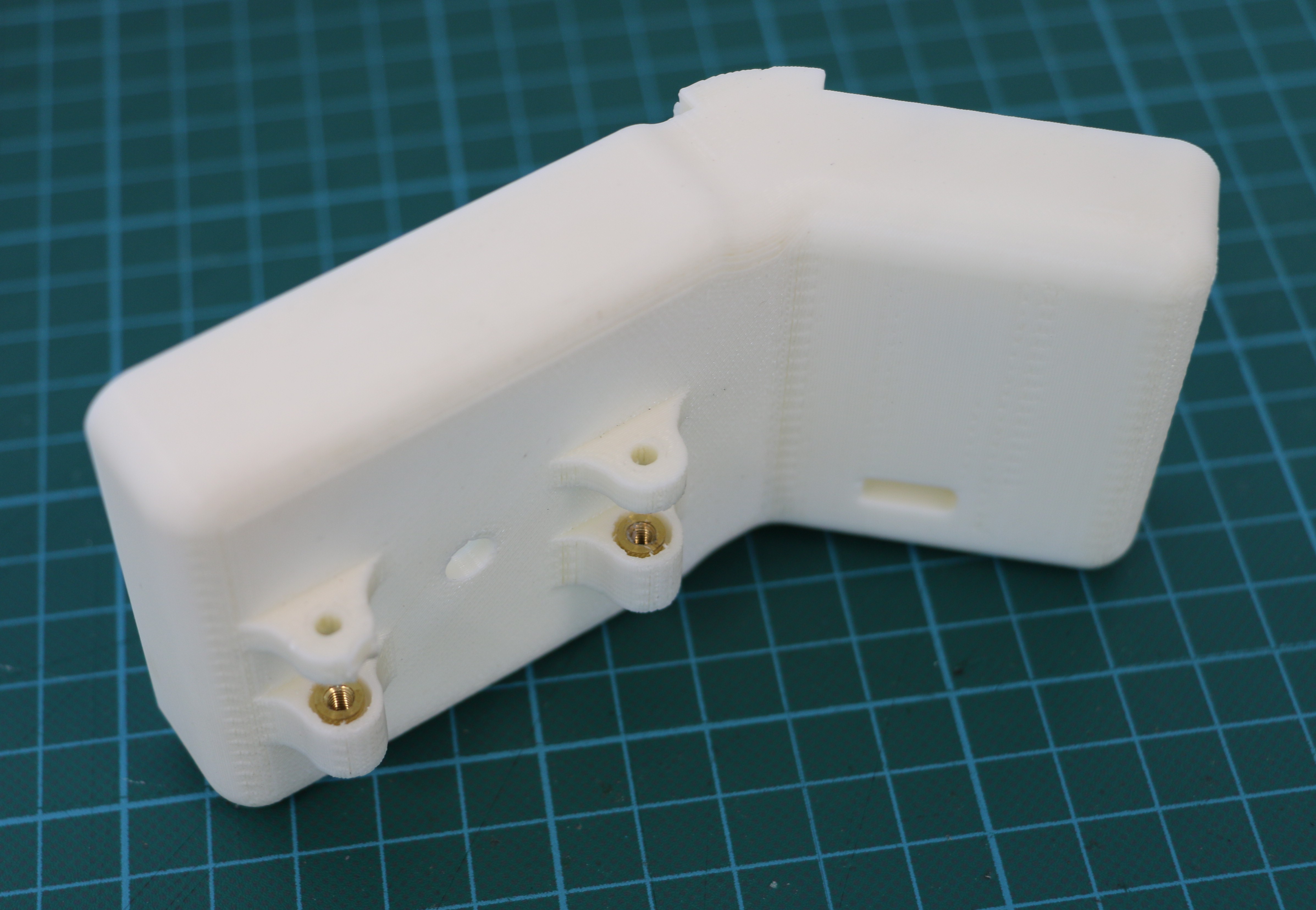
05/15/2018 at 19:54 • 0 commentsVersion 1.1 of the sensor case is complete and printed! The design changes were successful and the Geiger Tube and PCB fit much better now. Here are a few images of the final case design.
![]()
![]()
![]()
![]()
-
Sensor Casing Design Version 1.0
05/15/2018 at 19:18 • 0 commentsVersion 1.0 of the sensor case is complete and printed! Our goal is to design a radioactivity sensor package that is physically robust, simple, and easy to construct. We will be using a Turtlebot3 Burger robot for initial testing but also want the sensor package to be easily affixed to other robots, so the sensor attachment system also needs to be flexible.
The design is made to be 3D-printed, and encases the Geiger tube and electronics, keeping the high voltage components shielded from wandering fingers. The PCB is also angled back from the Geiger tube to prevent shielding effects.
![]()
![]()
![]()
Everything is held in place using M3x8 mm screws and Heatset threaded inserts. The inserts worked quite well.
Version 1.0 turned out well, but needs some slight modifications. In particular, the cavity for the Geiger tube is too tight and the electronics section is slightly too far again from the Geiger tube, which strains the cable. We also need to widen the connector hole on the back and deepen the electronics cavity. It’s not bad for a first iteration, and we’ll be making these changes soon and printing Version 1.1.
GeigerROS
A ROS enabled Geiger counter radiation sensor for easy robotic use. We use it on a Turtlebot3 robot for testing.