Before installing the motors, I suggest filling the gap between motors and hall sensor board with something soft and dielectric, like silicon or rubber, because the board is only held by 2 fragile terminals that will eventually break off due to mechanical stress
2
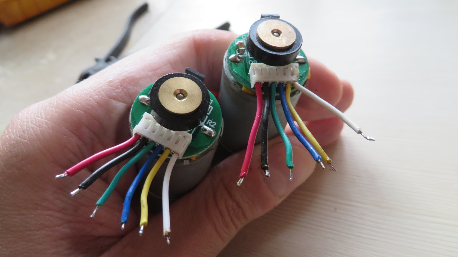
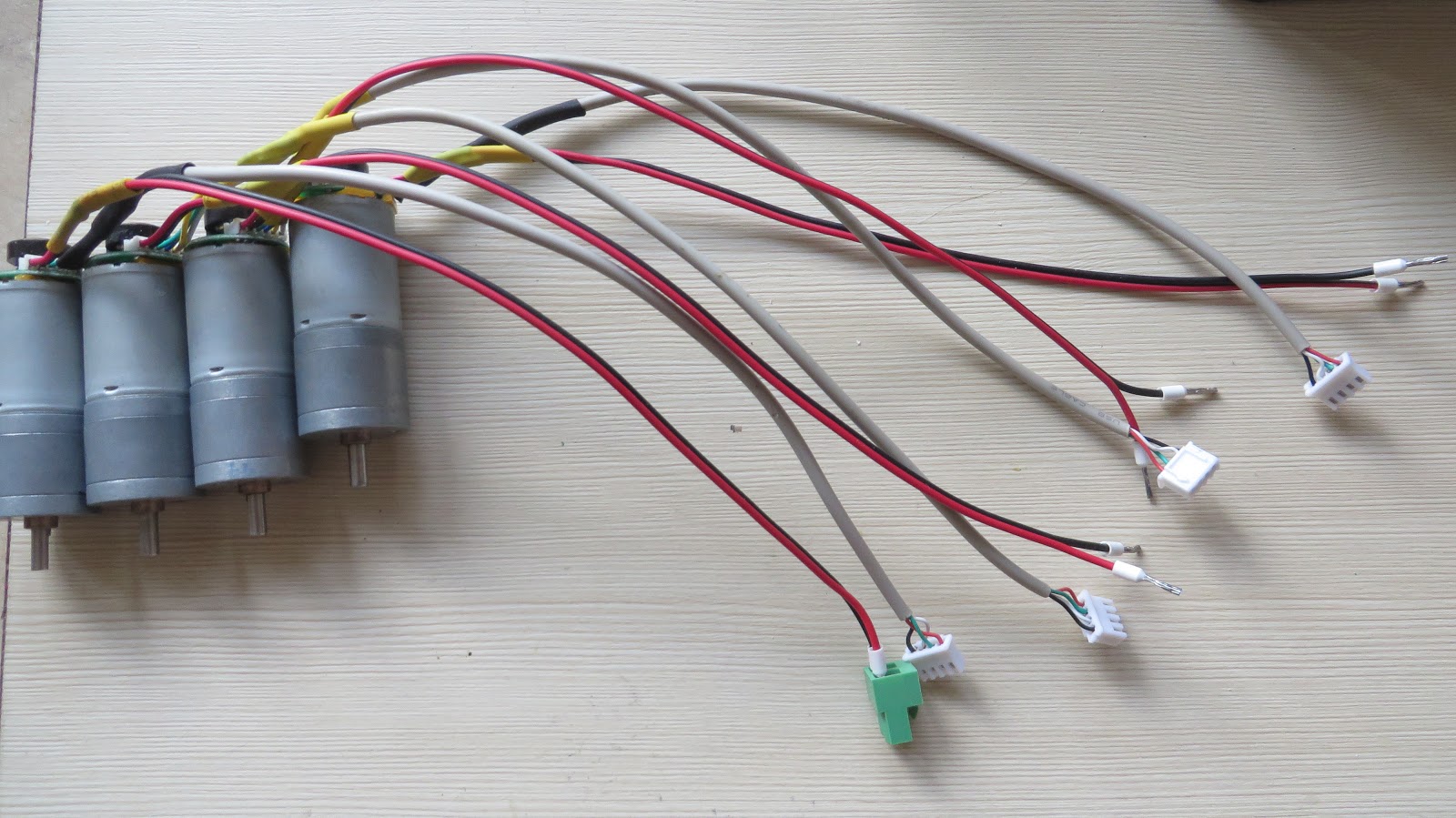
Electronics: replacing motor's wires, fitting them with connectors that match distribution board.
The wire that comes with motors was way too short, so I replaced it with the longer one, replacing the flimsy 6-pin connector with separate connector for power (motor wires) and signals (encoder wires).
Crop off the existing wires first. To see which color corresponds to which wire, see table on motor's product page.
We are going to separate signal and power lines on this motor. This
is actually the best practice in electronics engineering because it
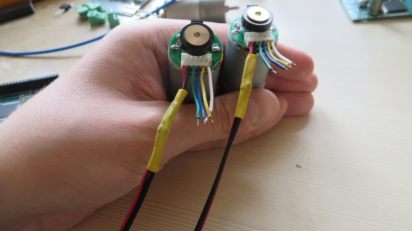
minimizes crosstalk between them. Solder a longer wire
to red and black wires and insulate them with heat shrink.
Let's lengthen the encoder's wires now. There's 4 wires total, 2 of
them signal and 2 power wires. Now, which insanely popular cable fits
the bill? USB - everyone these days has at least one in their house!
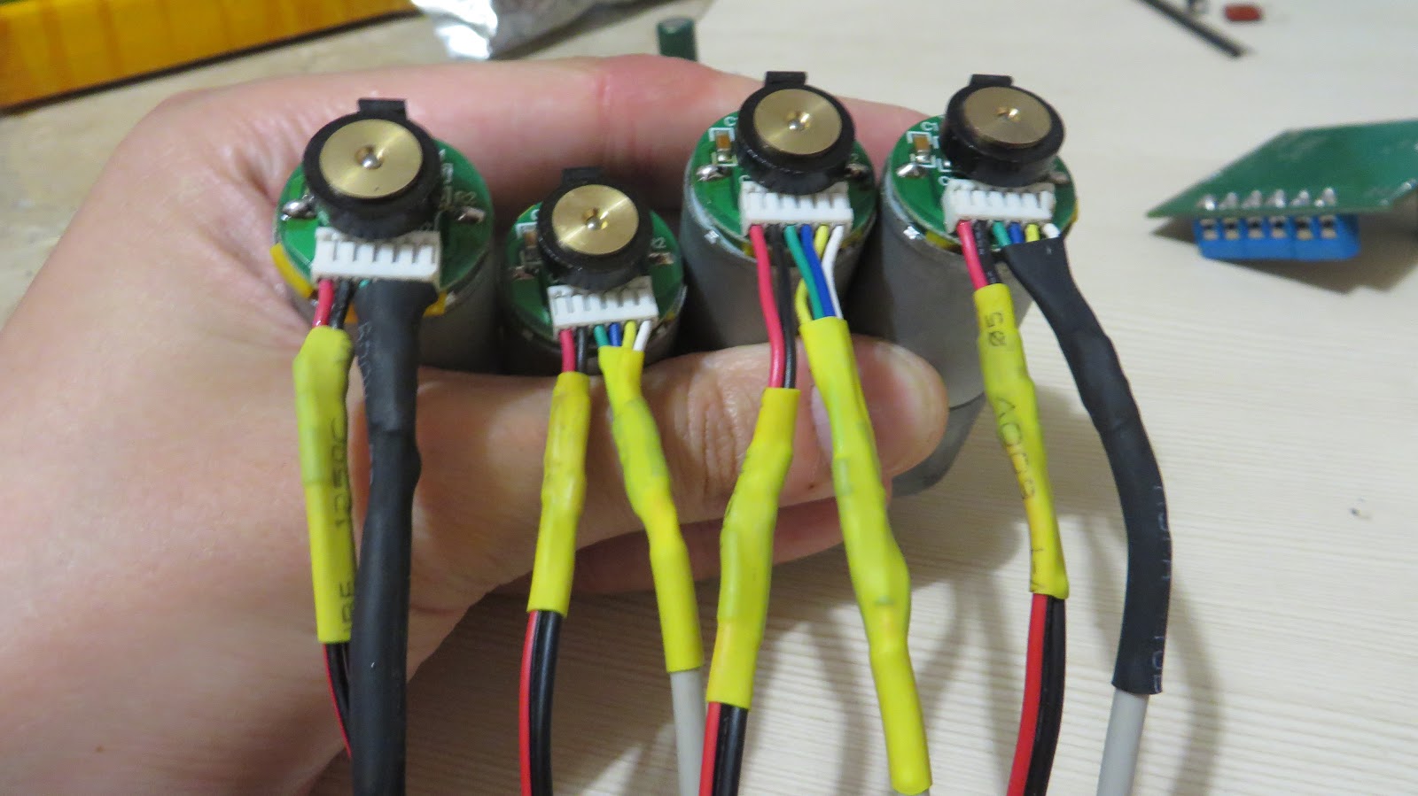
Butcher any cable you don't want for perfect pieces of 4-wire cable.
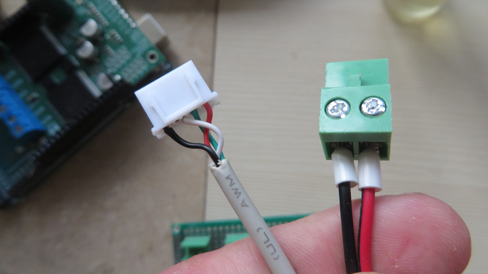
The opposite ends of motor's cables will need wire-to-board connectors.
That's what the result should look like:
3
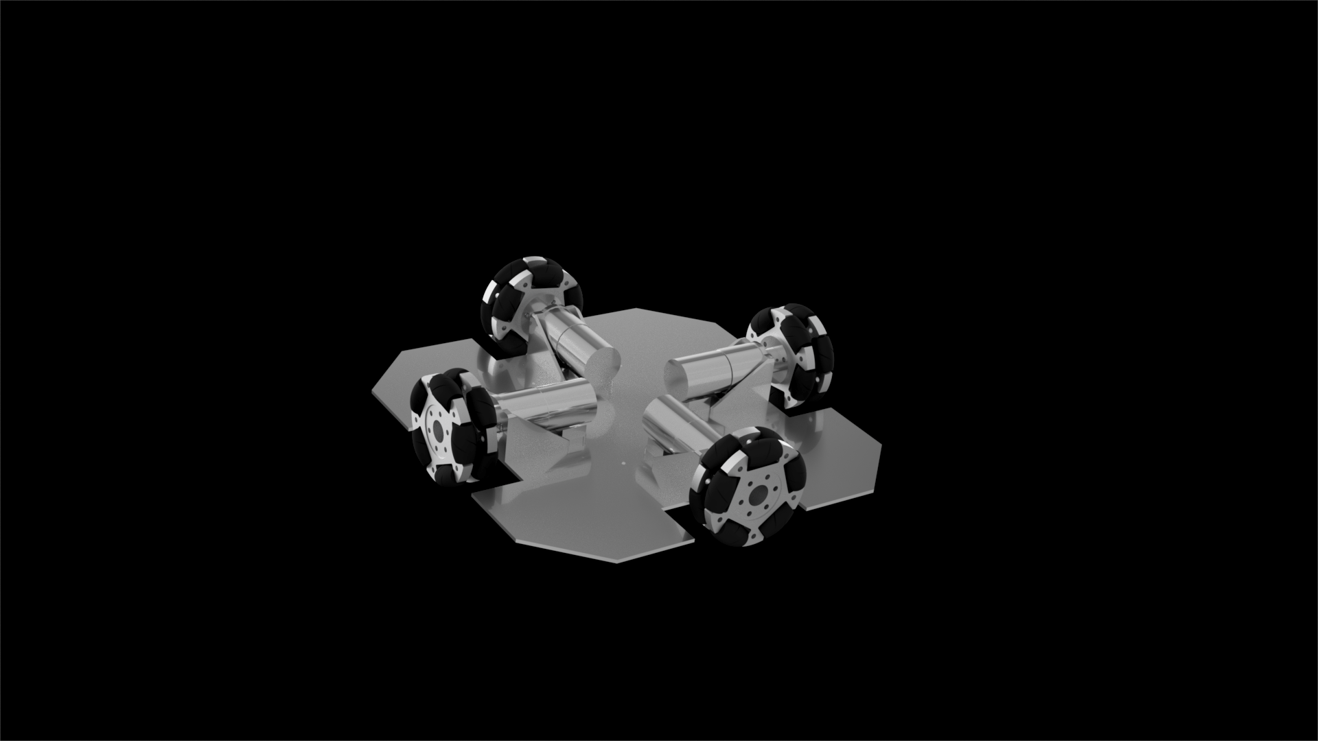
Mechanics: assemble the robot base
As the end result you're supposed to get a wheeled platform that will look like this:
4
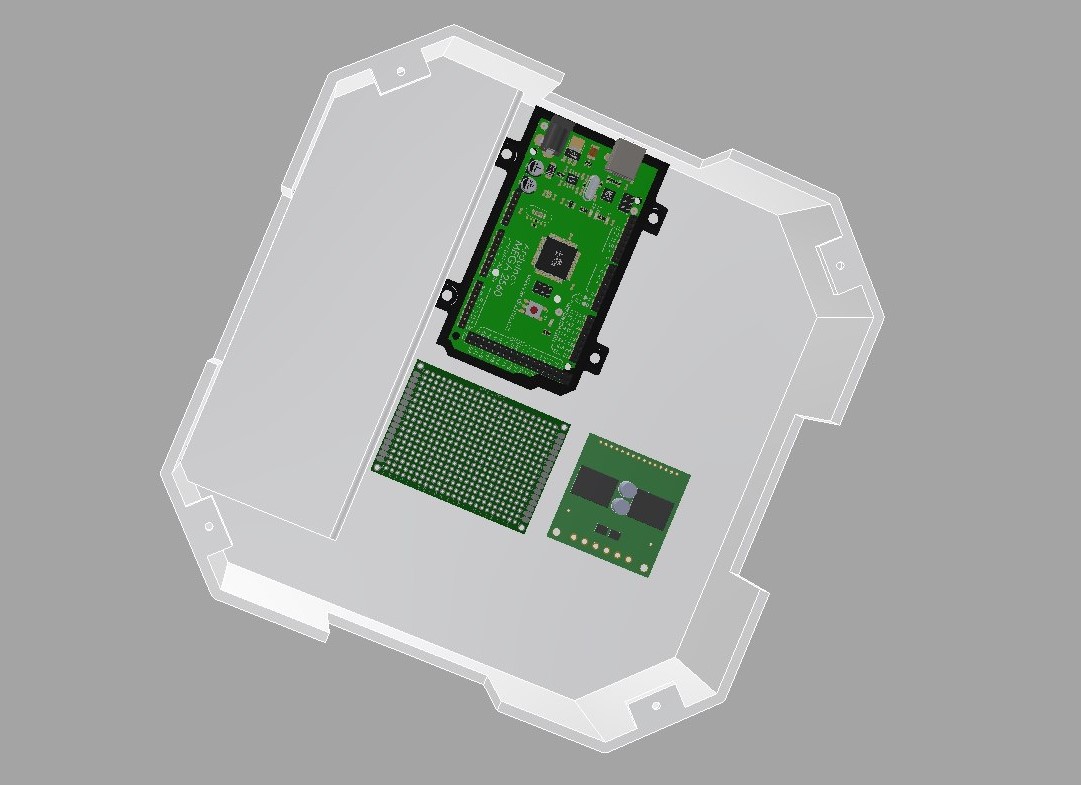
Mechanics: assemble the dome, connect electronics to the dome.
TODO - we still haven't figured out how to split the huge dome into printable parts, but you're supposed to assemble the dome and screw on the electronics:
5
Electronics: soldering it all together.
While assembling the robot base, we've installed our electronics on the underside of the dome covering the base. Now you can solder it all together according to this schematics in-place:
The full Kicad source and PDF render are attached to this project in Zip archive.
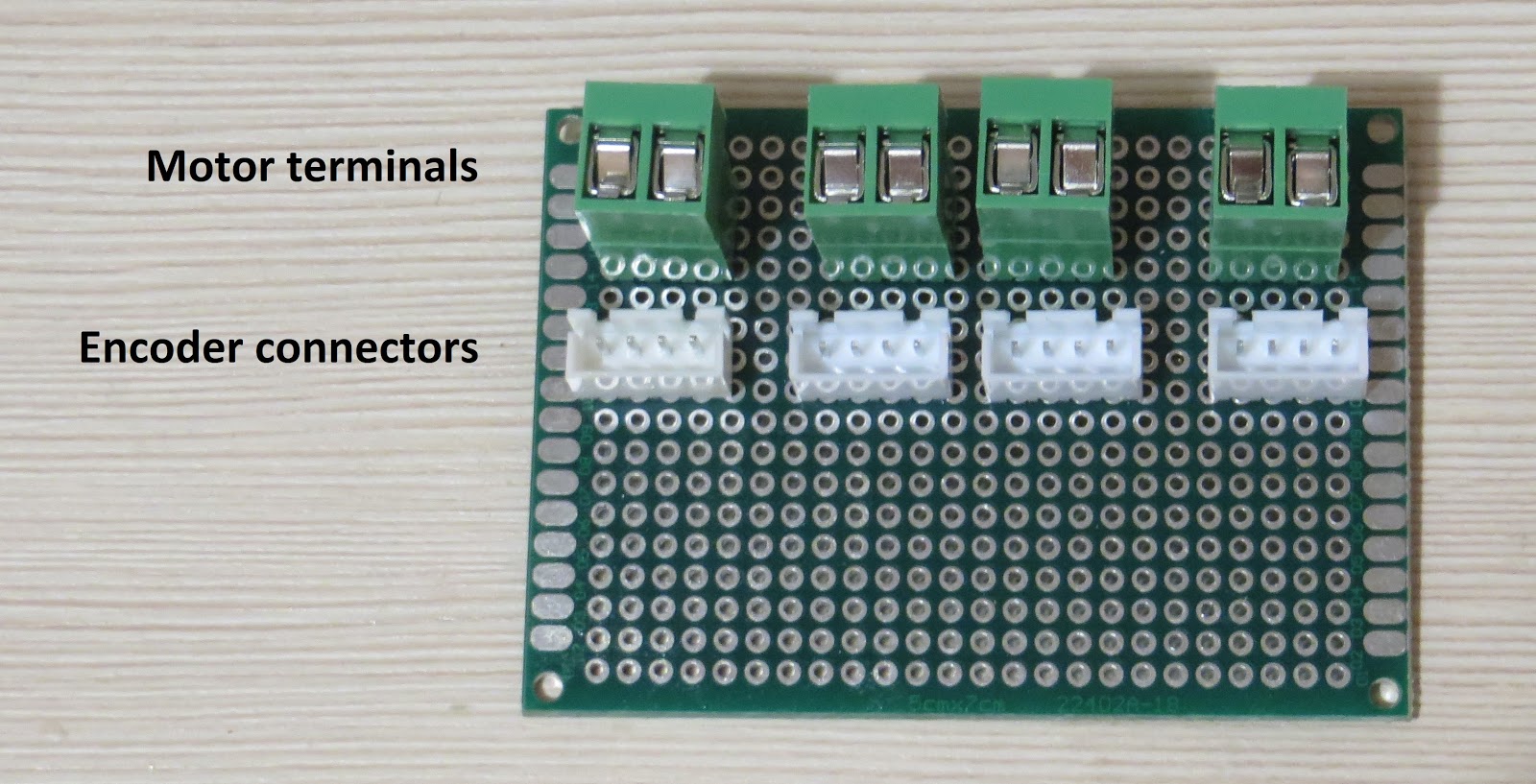
Before soldering, note the distribution board that's mentioned a lot in schematics. That's the part of schematics where battery voltage and 5V are wired to encoders, Arduino and motor shields. It also contains connectors that'll make for easy swapping and disconnecting motors and encoders later on.
Grab the perfboard and arrange the connectors first:
Solder the connectors to the board and the rest is just lots of routing:
 panovvv

Discussions
Become a Hackaday.io Member
Create an account to leave a comment. Already have an account? Log In.