-
Test with asymmetric load
08/27/2018 at 18:39 • 0 commentsOne more test . This time with a 15kg asymmetric load.
-
BLDC motor controller and filling the system
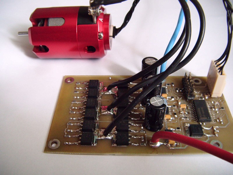
05/27/2018 at 19:54 • 0 commentsThe hydraulic system of the muscle module is powered with a 540 type , brushless motor. This type of the motor provides full control of torque and speed but require a dedicated controller.
![]()
The controller was build using MC33035 Brushless DC Motor Controller IC. The outputs of the chip are used to drive the high current MOSFET's with the help of the MIC4427 driver IC's. The current control loop is realized with the feedback resistor etched directly on the PCB. The complete schematic of the controller , as well as the GERBER files of the PCB can be found in the files section.
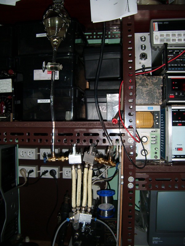
Filling the system , and bleeding the air of it is done with the tank installed above the muscles and pump and two service connectors for the schrader valves ( the type used for air conditioning repair ) .
![]()
The filling procedure:
- connect the service valves to the schrader valves
- open the valves and let the gravity fill the system with fluid
- start the pump and let it bleed the air.
- close the outlet valve and let the pump fill the muscle to its maximal capacity
- close the inlet valve and turn off the pump .
- disconnect the service valves and secure the schrader valves with caps.
This way both muscles are filled and have a positive pressure in the idle state.
-
The gear pump
05/27/2018 at 18:55 • 0 commentsThe second , most important part of the muscle module is the bidirectional , miniature gear pump . After a lengthy search I found a pump which is almost perfect for this project - a miniature gear pump made by MAGOM HRC company , and intended to be used in RC construction machinery models.
![]() The pump needs to be modified a bit :
The pump needs to be modified a bit :
- first remove all the hoses from the pump and unscrew the hose connectors
- remove the oil tank
- dismantle the pump
- remove the screw holding the pressure regulator , and dismantle it
- drill the pressure regulator hole with 4mm drill , and tap it with M5 tap
- thread the inlet hole in the pump cover with the M5 tap.
- plug the hose connector holes and oil tank mounting hole with headless screws
- install the 4mm push-in connector in the newly threaded M5 holes
- reassemble the pump
The modified pump should look like this :![]()
The last step is to install the BLDC motor. If the motor does not fit the pump it may be required to build an adapter and modify the original mount ( as it was it my case ) .
![]()
-
Building the actuator
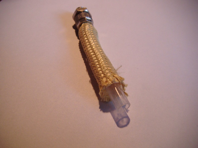
05/27/2018 at 17:41 • 0 commentsThe main part of the actuator is a silicone bladder made from 8 mm silicone hose. The hose is then encased in the aramid braided sleeve ( aramid cable sleeve ) and screwed into hose connectors. The length of the hose should be chosen to match the application , remembering that the shortening of the actuator is around 30 %.
Here is the cross section of the single "muscle"
![]()
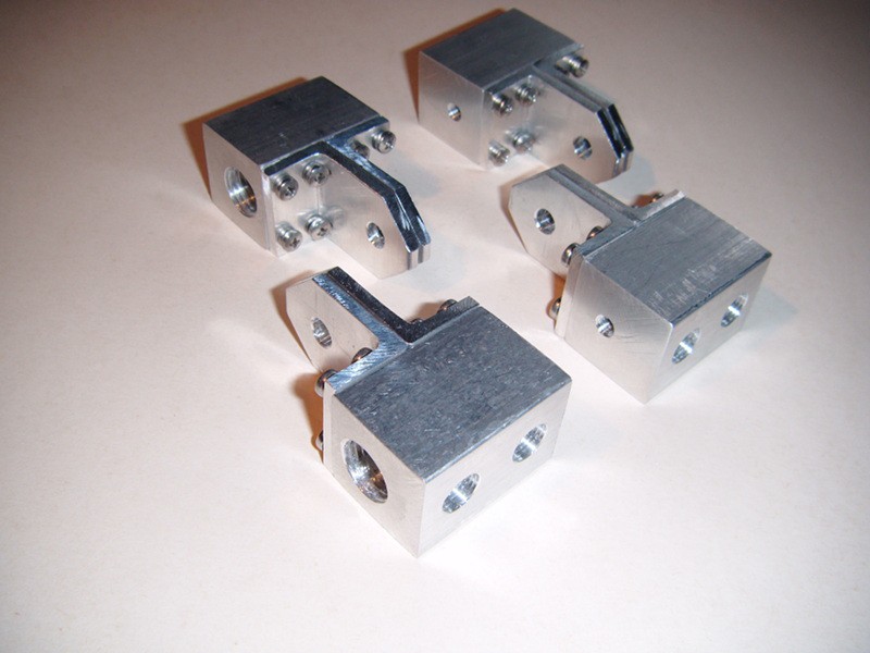
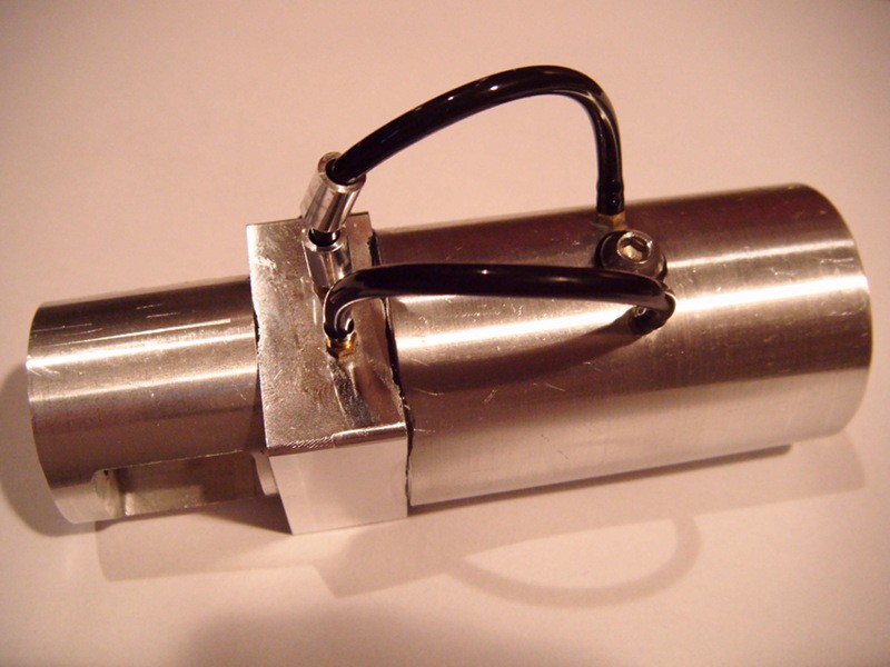
The bladders are installed between two aluminum blocks acting as the mounting elements and the conduit for the hydraulic fluid . The technical drawings of the blocks can be found in the files section of the project. If one needs more force exerted by the actuator the blocks can be extended and equipped with more "muscle bladders" connected in parallel .
![]()
As you can see , there are two types of mounting blocks . One is designed to be fitted with a 4mm push-in connector , the other should be fitted with a Schrader Valve . The 4mm connectors would be connected to the pump , while the Schrader Valve is needed for filling the system and bleeding the air out of it.
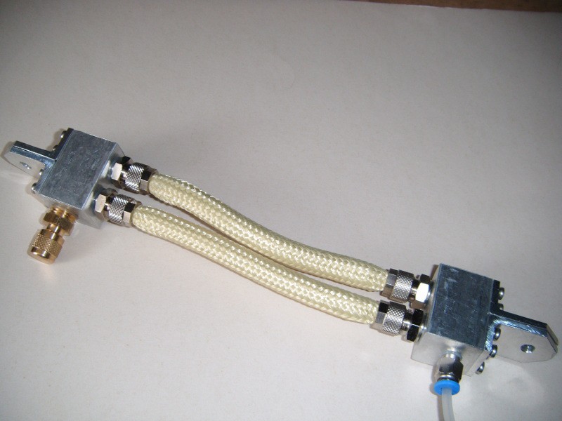
When all the parts are ready , all the connectors should be installed into the blocks first and sealed along the thread using either a dedicated sealant or a bit of epoxy . Then the hoses with the sleeves should be screwed into the connectors. The finished actuator should look like this :
![]()
Preloaded Hydraulic Muscle
Universal , scalable hydraulic muscle module.
 The pump needs to be modified a bit :