Close
0%
0%

JBC soldering station

Custom soldering station with JBC T245 pen

Similar projects worth following
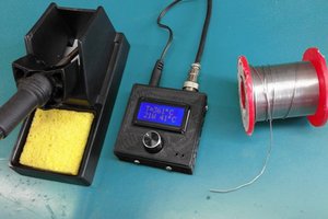
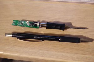
Original JBC soldering station is one of the best soldering tools, which could be purchased. But when we compare the price of original with the custom one, there are incomparable. So why not take only the pen and make a compromise? Of course, you can still buy the original, but... .

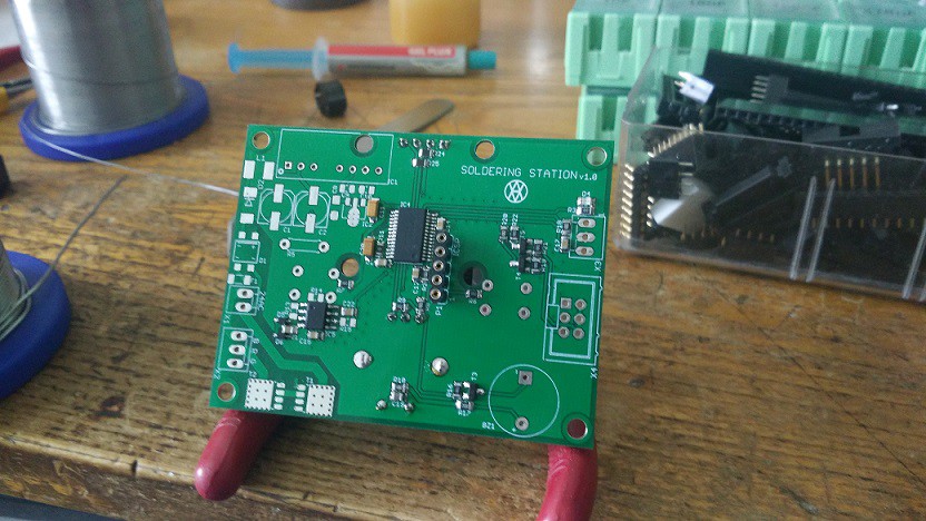
Soldering stations is based on 2-layer PCB, transformer and custom housing (future).

Power supply for pen 24V AC. There was a dilemma between power supply choosing, AC vs DC. There were prose and cons, like simpler switching, speed, saturation, isolation, temperature ... . After sum-up, I have chosen the AC one.

Basic concept:

The soldering pen will be switched via 2 MOS-fets. One for positive and second one for negative part of AC signal. There were multiple options to control MOS-fets, like R+C, another transistor, SSR and so on. I have chosen opto-coupler with integrated MOS-fet driver. Anyway grounds needs to be isolated due to coupling and interference. One option was to chose transformer with two winding or isolated DC/DC converter.

When the pen will be turned off, thermo-electric voltage from thermo-coupler will be amplified and measured via OPAMP. A difference between target and actual value will be controlled over some kind of regulator, like PID.

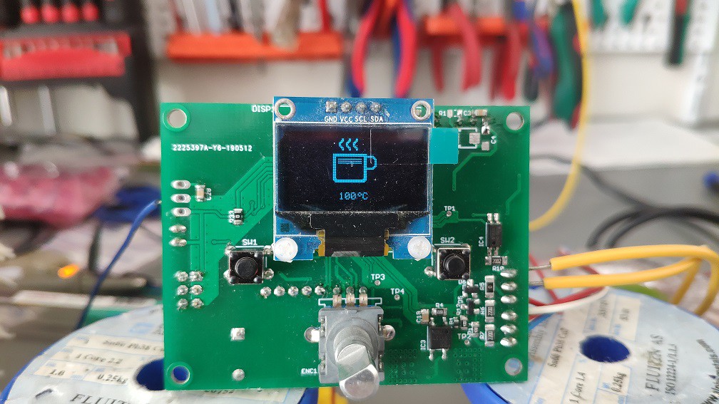
Device will be controlled from user-space over 2-switches (predefined quick temperature) and encoder (some settings). Response will be showed on OLED display.

Boards are now fabricated.
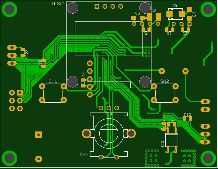
More details will be specified later, stay tuned... .

gerber_v1.3.zip

Gerber files

Zip Archive - 291.04 kB - 02/27/2020 at 07:16

Download

BOM_st.xls

Components

ms-excel - 12.00 kB - 08/16/2020 at 17:07

Download

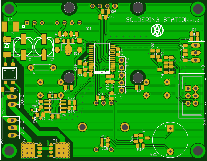
bot_assembly.jpg

BOTTOM layer assembly

JPEG Image - 80.82 kB - 02/27/2020 at 06:57

Preview

top_assembly.jpg

TOP layer assembly

JPEG Image - 56.76 kB - 02/27/2020 at 06:56

Preview

FW.zip

MCU Firmware file - v1.1

Zip Archive - 26.60 kB - 02/27/2020 at 06:57

Download

  • 1 × JBC T245 soldering pen
  • 1 × PIC32MM0128GPM MCU
  • 1 × APV112 Opto and Fiber Optic Semiconductors and ICs / Optocouplers and Optoisolators
  • 1 × AD8227 Amplifier and Linear ICs / Instrumentation Amplifiers
  • 1 × SSD1306 OLED display

View all 6 components

  • Device released

    Andy02/27/2020 at 07:09 4 comments

    I was waiting for some last parts to make the device "ready for usage".

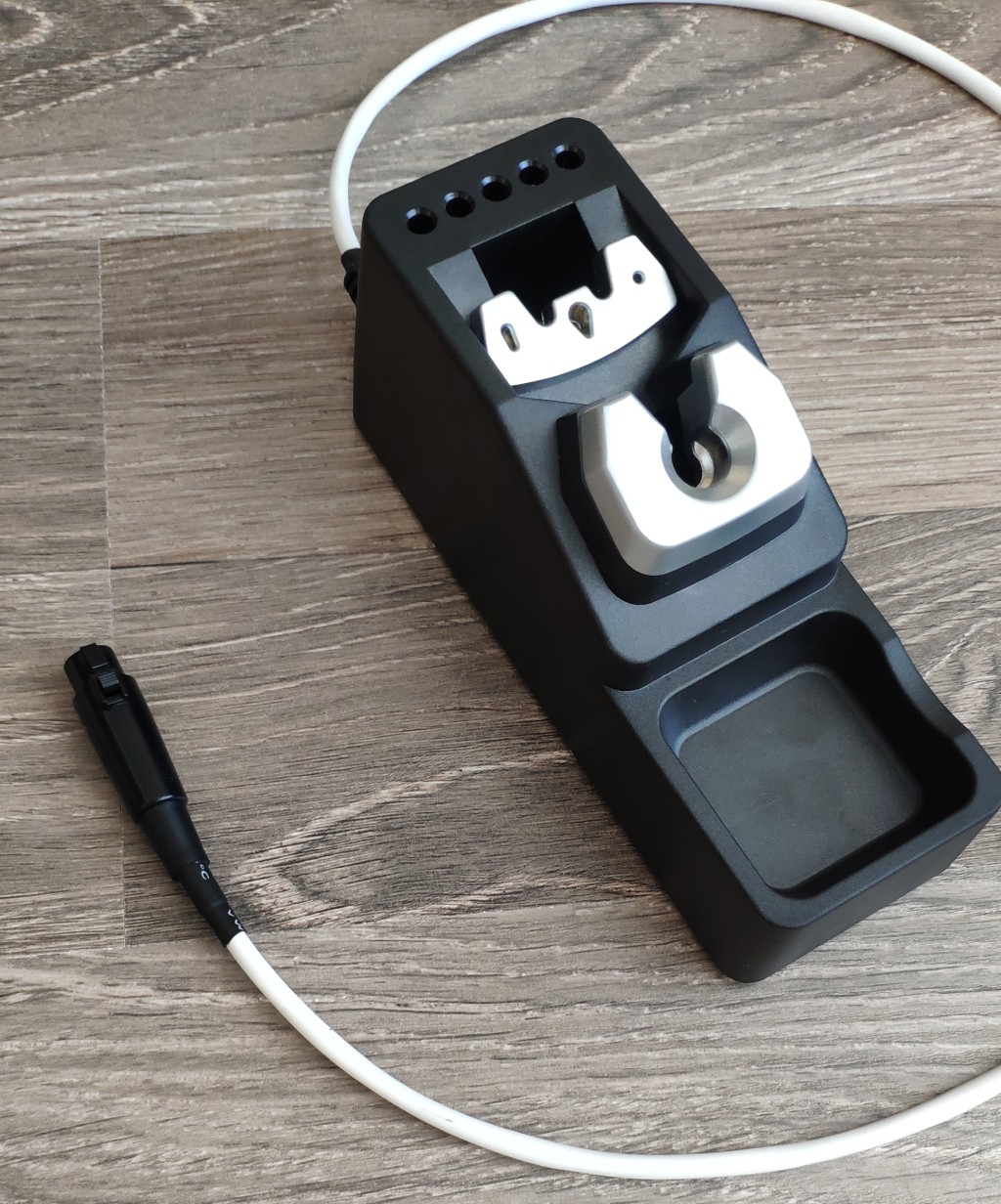
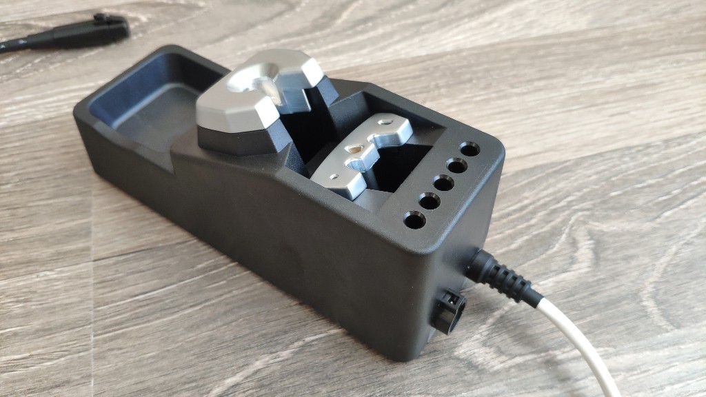
    Of course, it was also usable without this last missing part (a stand). But why not make this station little bit better? So I have ordered some "Chinese" soldering station holder, which was pretty close to original JBC holder. Here are some results, after necessary modifications...

    So I think, now I can set the project to "finished".

    The last most important think is that ... . After very long thinking I have made a decision, that I will make the project a public. Anyone can make this device by yourself. I will be very happy, if I see some other users same satisfied as me.

    Happy building!

  • Release ready

    Andy12/26/2019 at 19:36 3 comments

    After a long time... everything is ready for usage.

    There were two big problems, which were discovered during final assembling. I have removed the programmer and tried to power the circuit itself via DC/DC converter.

    I have to made a new boards with fixed DC/DC connection and zero-cross detection. New capacitors, different GND connection and new zero-cross circuit. How did I discover it?

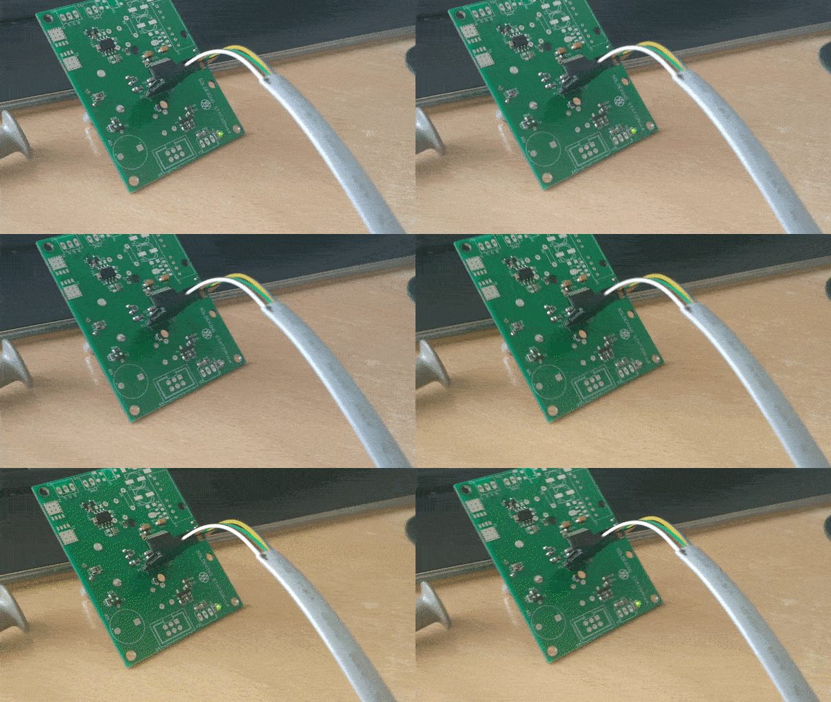
    Just disconnected programmer, it means, that there was no a general GND anymore. Everything was isolated. There was a lot of noise on 3v3 from LDO, which transferred into input (5V). Which made circuit really unstable. So some capacity and better GND re-planning was required.

    Next problem (I think, the main) was on the soldering tip detection. After a global GND missing, one input on OPAMP was flying. It means -> noise on the output. So I have to identified and fixed it. Hopefully it was only on the SW side.

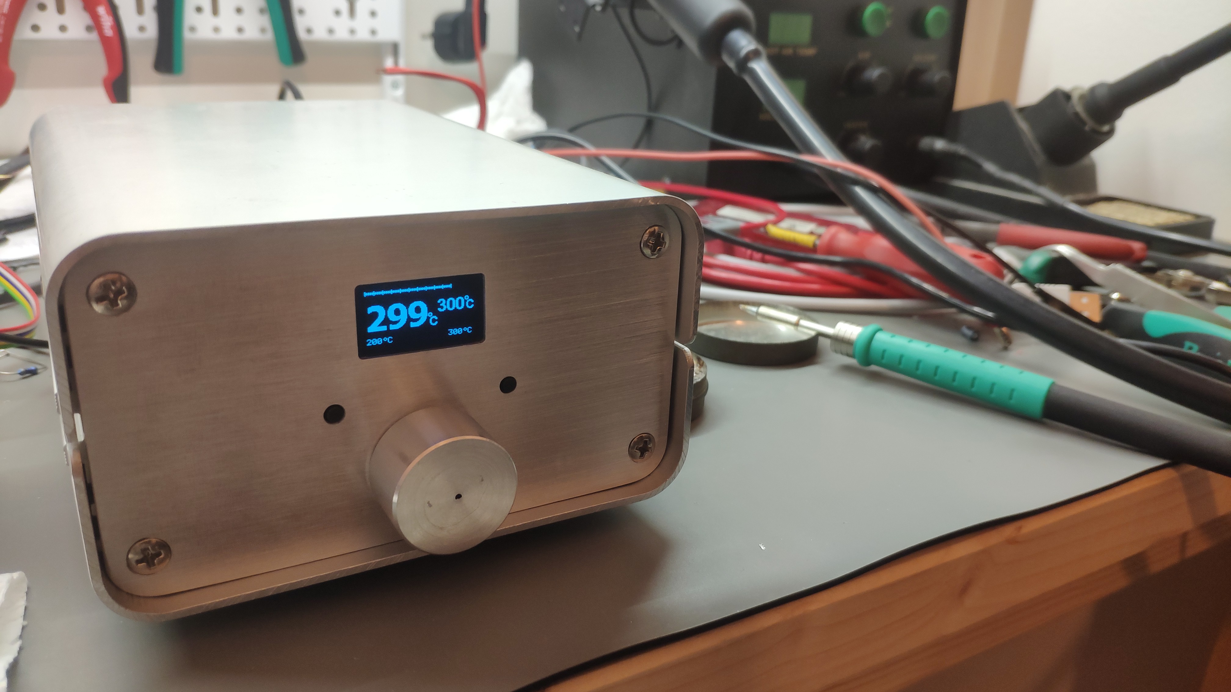
    So here are the final results.


    So what is missing here?

    Nothing... maybe a stand :).

  • Device assembled

    Andy10/26/2019 at 18:16 0 comments

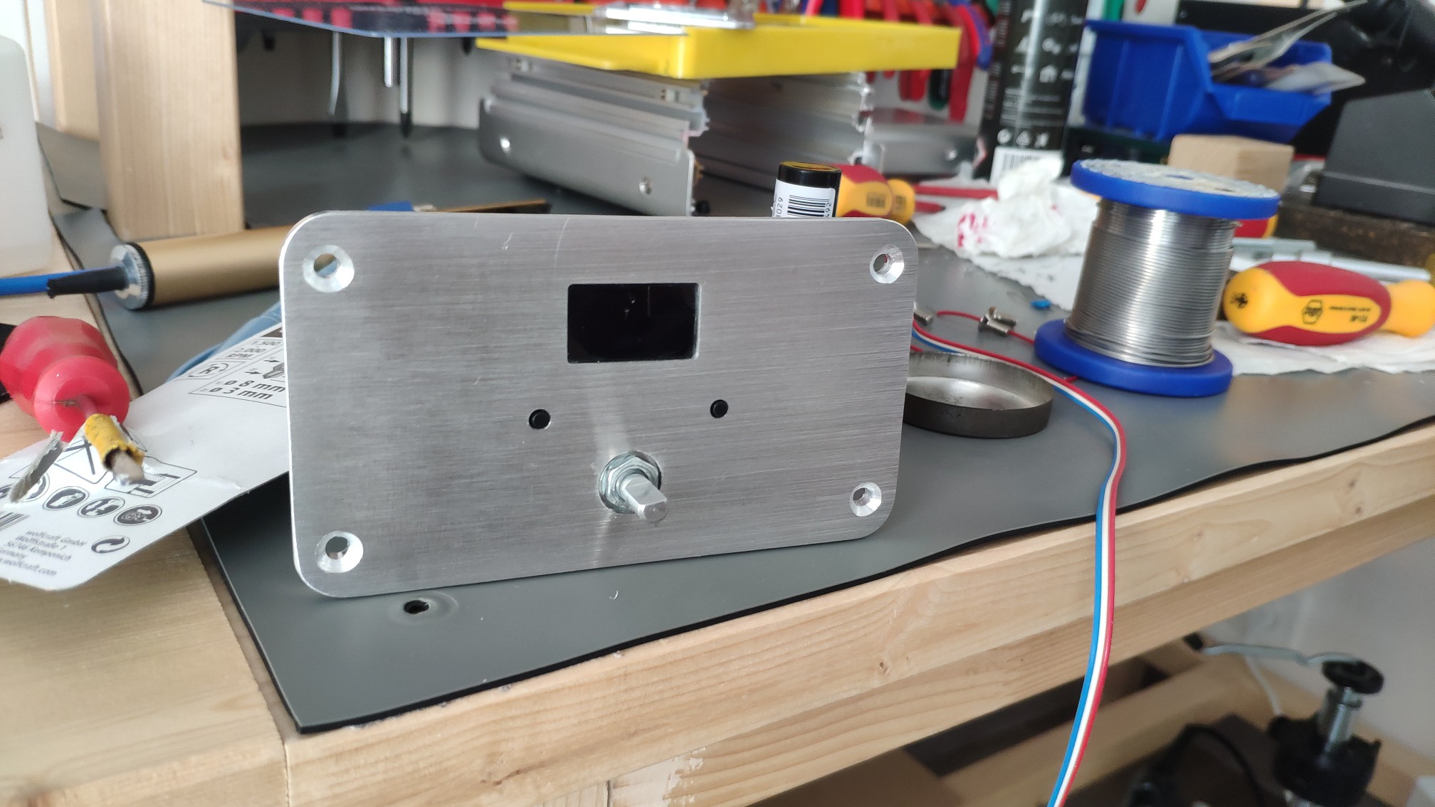
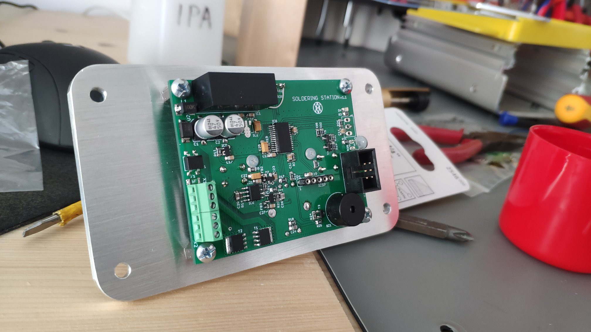
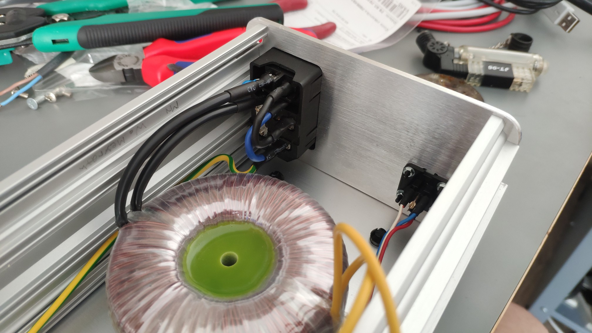
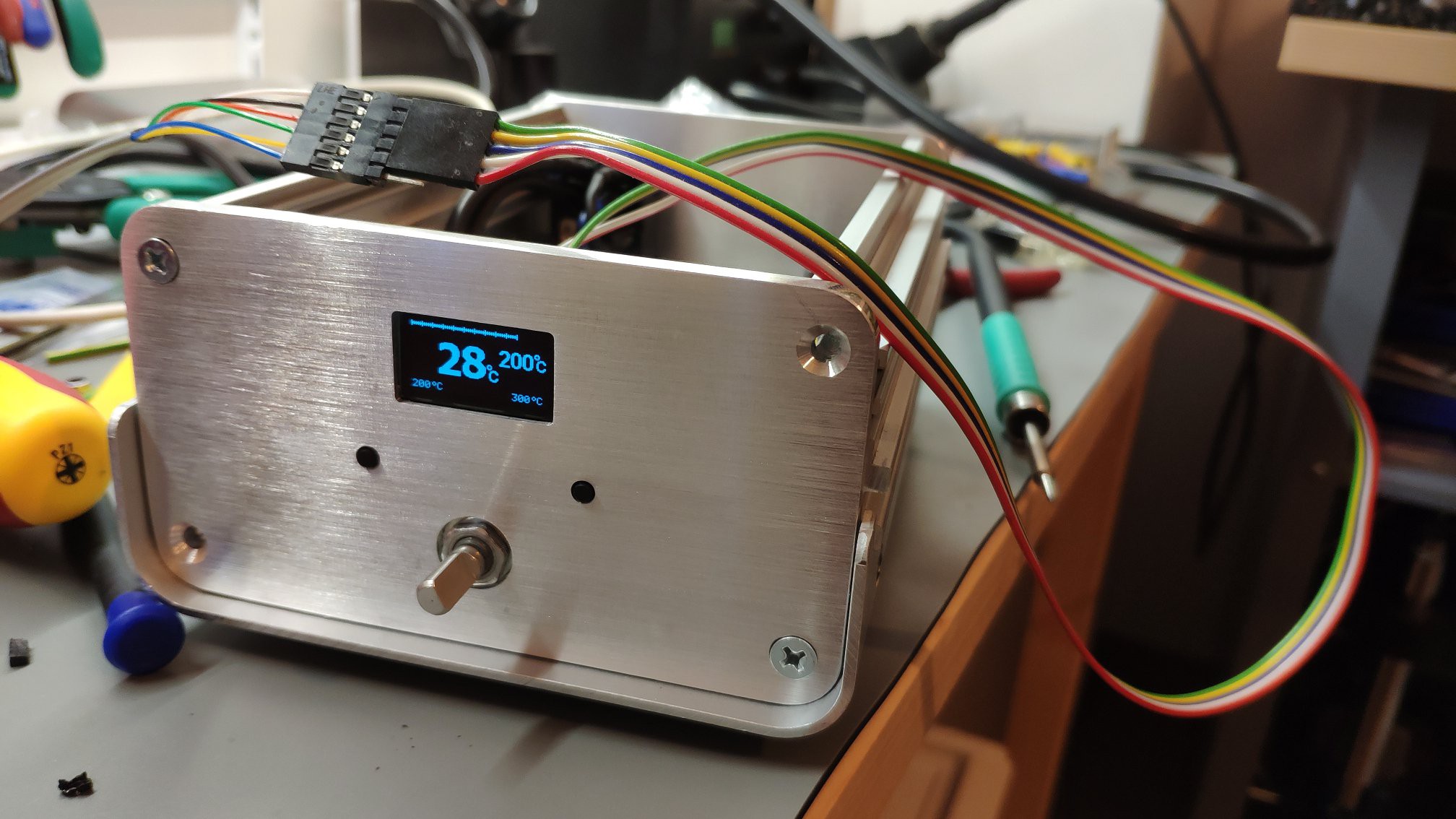
    I was waiting for housing to be fabricated a little bit. This is the main reason, why I didn't post any progress here.

    Meanwhile I was working on different project (CNC). But this is an another story :).

    I think better is to post pictures without useless slacking...


    Hopefully nothing has been broken during final assembling.

    Now I have to wait for encoder knob fabrication. I think, this is the last part of the puzzle, which is missing now. Of course stand is also missing, but this is not major thing, which could breaks soldering station using.

  • SW ready for using

    Andy09/20/2019 at 09:37 0 comments

    I would like sum-up what is currently working and what is the future prune.

    All pending features, which were blocking a real using have been fixed, hopefully. Some of them have been moved into future, because they are only minor improvements, I think.

    Ok, lets go to sum-up (I will re-use TODO list from previous log):
     - sleep mode
      - A sleep temperature is also showed. This is starting after sleeping timeout has been elapsed only when pen is inside a stand. It can be disabled of course.

     - protection handling
      - Added Watchdog and some min/max checking
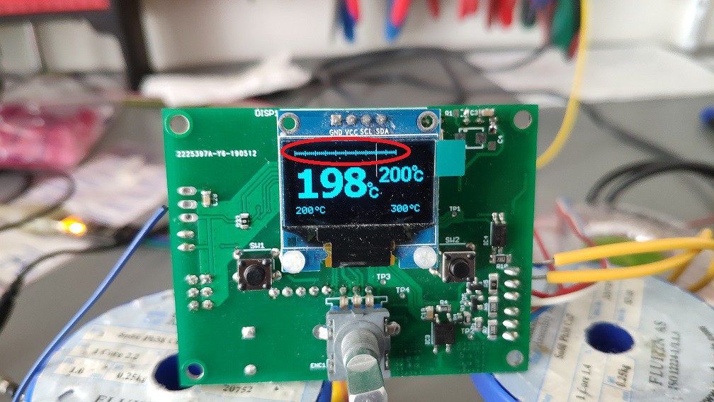
     - power bar handling
      - If a temperature difference is bigger than zero, power-bar is filled. It also indicates pen heating.

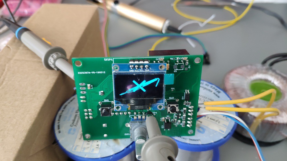
     - pen detection
       - If then pen is missing, logo with crossed pen will be shown. It also turn-off heating. After pen is connected back, it automatically starts heating.

     - °C/F switching
     - I don't want to waste a time with this selection. I don't want to use F for temperature displaying. Maybe I can add it in the feature for some user request.
     - brightness regulation
      -  There are 10 options to set brightness level. Levels are directly represented, so user shouldn't save the parameters to see, how the brightness really looks like.


    Others not previously mentioned improvements:
     - multiplier
       - Temperature could be de/increase not only be 1 degree. It could be changed by 2, 3, ... 10. User doesn't need to go step-by-step if he wants to de/increase temperature eg. 200->300.
     - beep
      - All user inputs could have also sound echo.
     - performance improvements
      - Heating now takes less time. Here I need to experiment a little bit to get more power. But I it's not urgent, so I am shifting it to the future.


    That's it. I would like to say really thanks all people, who helped and gave me some advice for SW/HW improvements.
    I think, that SW part is ready for usage. Now I will move to housing. I have to change my previous drafts a little bit to be matching with actual design.

  • First real heating

    Andy08/15/2019 at 06:54 0 comments

    After some time, I would like to summarize, what was is actually done and bring some info.

    I was struggling with some not working parts like EEPROM, correct temperature measuring, heating... , but finally I have found the root cause and fixed it. Last part, which needs to be clarified, was user interface. I have made some, how to say "preliminary" version, but It looks fine from my side. Maybe I will modified it a little bit afterwards.

    What is actually working/done:
     - User interface
     - buttons handling (rotary encoder, user buttons)
     - temperature measuring (ambient, heating)
     - display controlling (SSD1306)
     - parameters saving (EEPROM)
     - calibration (external more precision temperature meter required)

    What needs to be fixed/done:
     - sleep mode
     - protection handling
     - power bar handling
     - pen detection
     - stand detection
     - °C/F switching
     - brightness regulation


    Here are some videos, how the real prototype looks like.


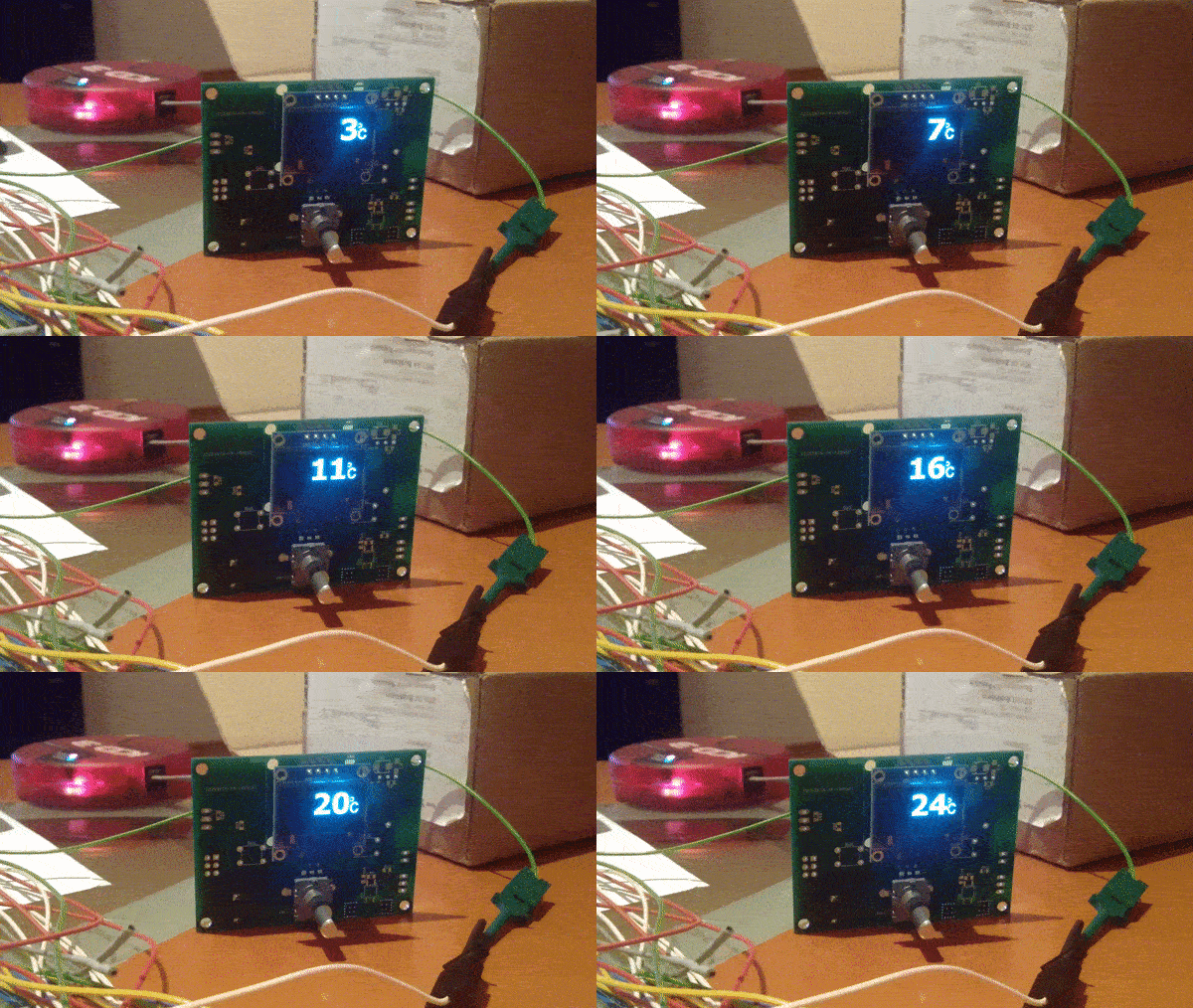
    Cold heating from ambient to target temperature (25->200)

    User interface, menu handling

    Actually there is still lot of work. Next step is to verify, if heating algorithm is the correct one, or some tuning is required.

  • PCB ready for assembly

    Andy06/04/2019 at 19:42 0 comments

    Magic happened and PCBs are at home, finally... .
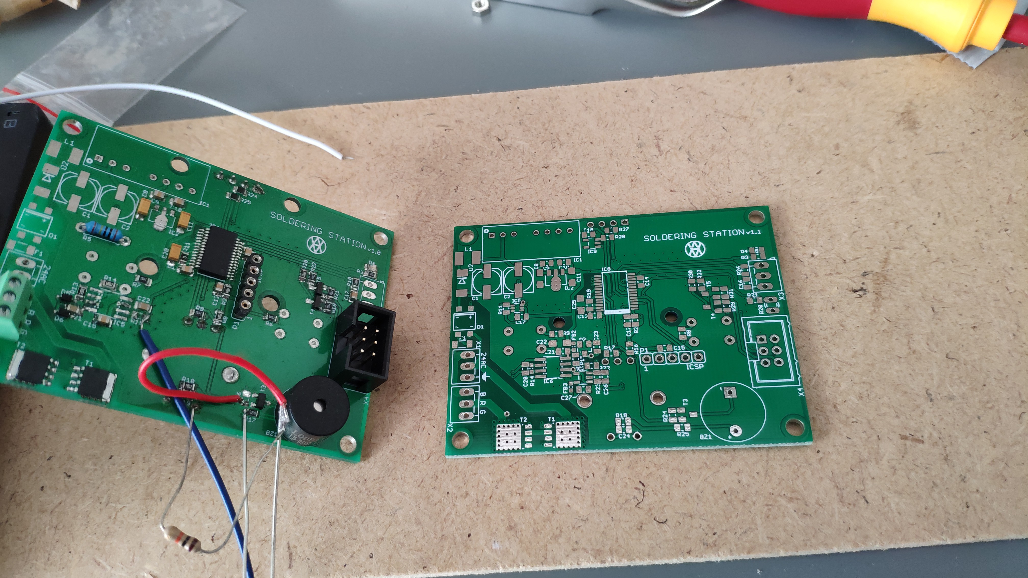
    On the left side is version 1.0 and on the right side is new PCB version 1.1 .
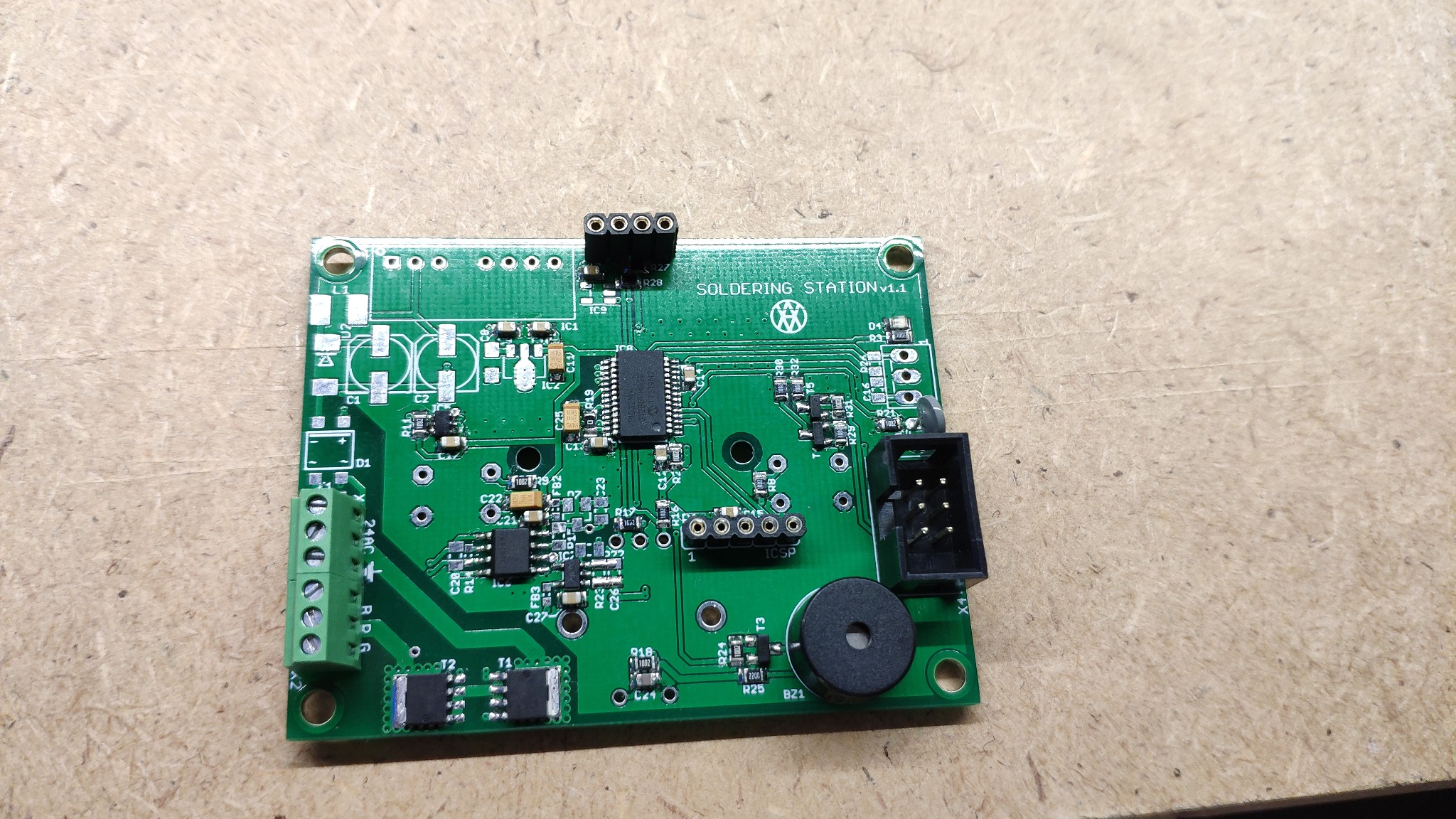
    Some components has been taken from previous version. Finally "Hello world!" (LEDblinking) is working as well.
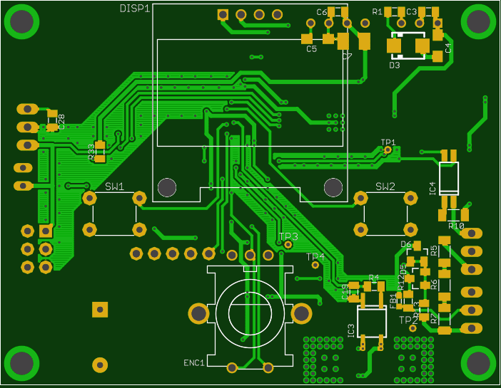
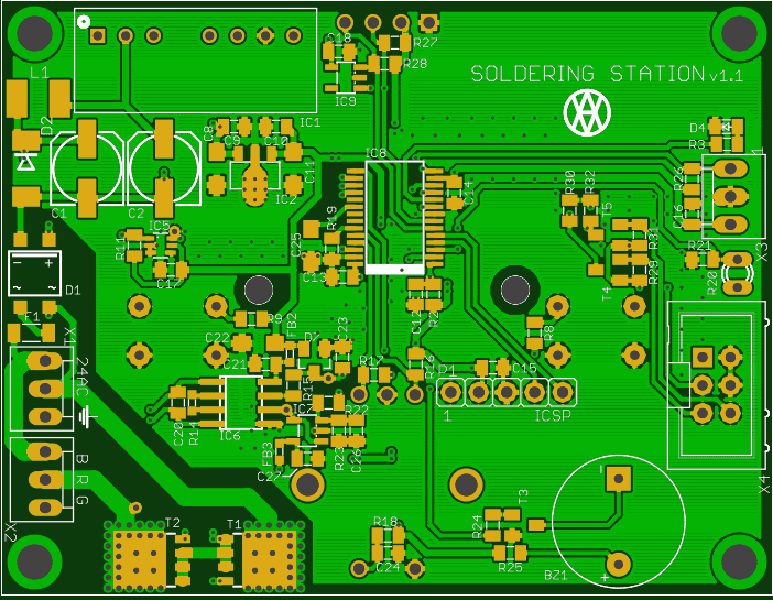
    Now I have to buy some missing components. After that I will continue in assembling.

  • Moving forward

    Andy05/13/2019 at 06:56 0 comments

    First, I would like to say sorry for not posting any progress here.

    I was moving my home laboratory to new location. More space, more gadgets, new ideas ;).

    Previous concept has some issues. Like zero-cross detection was not working like expectations. (I have already published working idea).
    Another problem was with temperature measuring. Maybe you know that, temperature is changing in uV. Previous solution has lot of noise on AMP inputs. So I have modified the measuring technique a little bit. Now I am measuring it like a differential. So noise is on the both of inputs and it equals to quite good signal.

    Last problem was with the switching itself. I was noticed on this problem by @Attila Kovács . He gave me a lot of advice, which I would like to say, thank you.

    After some modifications I have finished a new PCB design v1.1. (I hope, this is the last one :) ).

    Now I have to wait for fabrication... .

  • Some progress

    Andy10/01/2018 at 18:10 2 comments

    Sorry for the longer delay between posting some progress. I didn't have much time for continuing in this project. Of course there were some tryings and strugglings with zero-cross detection.

    First idea was, to use for zero-cross detection basic external interrupt. I used signal generator for testing. Input signal was sinus @50Hz. When I connected the signal to MCU, there were some delay between reaching the zero level and interrupt itself. MCU was running with 8MHz internal oscillator. Delay was  ~4ms, what is unacceptable (1/50Hz = 25ms). I have tested it on 8-bit MCU, to be sure, if there is something wrong. But results were the same. "Maybe there is a problem with internal oscillator". So I have decided to use external one, but without success.

    So I have switched the input signal to square and it was working well. After some analysis (including datasheet) I have figured out, that is missing "Schmidt circuit" on MCU's inputs. The edge of input sinus signal is not so perpendicular as expectations. It means that, external interrupt mechanism can't reach this edge.

    Finally I have the solution, how to fix this problem. I didn't want to use 4-way rectifier and stuff like that. So a comparator is the right way. But, which one to use, external or internal... . External has some advantages, so I decided to use this one.
    I have made only simulation, but it should work ;)

    http://tinyurl.com/y9fj429h

  • OLED SSD1306 is working...

    Andy07/24/2018 at 20:06 0 comments

    It was funny to port i2c driver from 8-bit to 32-bit MCU. Lot of changes, but it was a big step forward. So seems to be that,  I have successfully ported my previously used OLED SSD1306 driver.


    It just counts from 0-300, but image was stripped ;). I guess, for basic presentation is enough.

    There is a lot of TODO points, but next step will be displaying value based on encoder rotation... .

  • Prototype assembling

    Andy07/22/2018 at 14:23 0 comments

    I have had some time to assembly a first prototype. There is a minimum components to verify basic functionality.

    Now is time to check if everything is working in quick steps.

    Hello world is seems to be working as well ;)

View all 12 project logs

Enjoy this project?

Share

Discussions

Thomas Hilson wrote 09/01/2024 at 13:52 point

Hey, I was interested in the stand you found. It looks quite good compared to all the crap I see on Aliexpress. I saw you posted a link to it but it does not work for me. Do you still know what it was called so I can find it ?

  Are you sure? yes | no

Andy wrote 09/01/2024 at 19:23 point

Hello, I bought it from there, search for "t12-11 soldering station stand". Uff, the price wasn't as big as now.

  Are you sure? yes | no

Thomas Hilson wrote 09/01/2024 at 21:26 point

Hey, thank you for your quick reply. It is indeed quite pricey, but still a third of the genuine JBC one. I may try to make a custom one for this price ...

  Are you sure? yes | no

muhammad nour elmogy wrote 10/26/2023 at 23:23 point

It would be great if you can release the schematics! 

I am trying to build my own but since I will not use the same microcontroller,  I would like to take a look on how did you read the temp. and control the heater.

Thanks

  Are you sure? yes | no

Andy wrote 12/27/2023 at 18:52 point

As we discussed it via PM, it's not "fully" open source. I gave there a files, with in is possible to build this project.

  Are you sure? yes | no

mpeg36 wrote 09/25/2023 at 20:00 point

I have a question, do you have newer firmware? since you which is located in the files does not work correctly. There are menu items different from yours that you showed in the video.

  Are you sure? yes | no

Andy wrote 09/25/2023 at 21:38 point

Nope, the files here are the latest one. I send you an PM to discribe the issue more properly. 

  Are you sure? yes | no

Jakub Grobis wrote 11/17/2021 at 20:29 point

Hi. I working on Yours project, but I have few difficulties. First of all JP1 and JP2 need to be connected or disconnected (current state disconnected). After trying to power circuit up. Fuse is exploding. Any idea what should I check? Thanks

  Are you sure? yes | no

Andy wrote 11/17/2021 at 20:59 point

Hello,
JPs are solder jumpers, so they have to be soldered out, only when related TP (test-point) has correct value.

- JP1 (TP1) should have 5V at the output. So don't solder it, while, there is no 5V
- JP2 (TP2) should have 3V3 at the output. So don't solder it, while there is no 5V at the IC2.2 and 3V3.

Regrading to exploding fuse, don't continue for next components, while AC/DC block this is not fixed!
- X1.1 and X1.2 is 24V AC input

- IC1 is DC/DC converter (24->5), try to remove it, measure the place, where IC1.1 and IC2.2 were connected, if there is no short circuit.

 - If not, continue with bringing back the IC1

 - if yes, check the capacitor C1 and diodes D1, D2

Generally start assembling with power-supply block then go for next parts.

Wish you good, luck!

  Are you sure? yes | no

Jakub Grobis wrote 11/18/2021 at 08:57 point

Something is really broken (or maybe it's IC1?) or I am not able to do it correctly. I tried to make new board with new components (D1 D2 etc. only IC1 is from previous board) capacitor is blowing again  EDIT: IC1 is problematic. I need to buy new one, problem is that I can not get any from EU :(

  Are you sure? yes | no

Andy wrote 11/18/2021 at 19:09 point

Uff, that's a pity. How did you break it? How did you check that, is broken?
- Didn't you connect the AC voltage there?
- Didn't you swap input with output?
What about to connect a smaller voltage and measure the input current and output voltage?

  Are you sure? yes | no

Jakub Grobis wrote 11/20/2021 at 15:34 point

After a lot of time and remaking everything I noticed that IC5 is doing some bad things. I think that i have wrong part over there :(. One more question, should display turn on without IC5 package?

  Are you sure? yes | no

Andy wrote 11/20/2021 at 19:58 point

IC5 is for zero crossing. Display should display logo without any dependency on IC5.

  Are you sure? yes | no

unal_akdogan wrote 09/28/2021 at 12:27 point

Hi, I can't supply SSSOP28 PIC32MM0128GP microcontroller. Can you write an alternative more common model? ? Or product link

  Are you sure? yes | no

Andy wrote 09/28/2021 at 13:11 point

Hello,

I'm not sure if there is some problem to find the correct MCU, but I used PIC32MM0128GPM028 (https://www.microchip.com/en-us/product/PIC32MM0128GPM028) :). It's possible to use the also the bigger one (PIC32MM0256GPM028), maybe the smaller one (PIC32MM0064GPM028) too, but I didn't check that.

  Are you sure? yes | no

Jakub Tomeš wrote 02/27/2021 at 10:22 point

Hi, I am kinda lost with the bom. I am trying to find a replacement for the smc_a capacitor on lcsc and can not find anything. Can you suggest a supplier?

Edit: I am very new to surface mount, so may be missing something

  Are you sure? yes | no

Andy wrote 03/20/2021 at 13:39 point

First, I'm apologizing to you, that I didn't catch your question earlier. 

Basically it's a Tantalum capacitor in A package, which is very common.

  Are you sure? yes | no

s1335db wrote 08/15/2020 at 05:28 point

I have another question, please: why power bar is not increase or decrease? I thought is based on how much power is applied on the pen...

  Are you sure? yes | no

Andy wrote 08/15/2020 at 08:50 point

Hello,

Why do you think, that power bar is not inc/dec? Did you see all videos?

  Are you sure? yes | no

s1335db wrote 08/15/2020 at 09:07 point

Cool! I think I did see all video but it seems that I missed some. Thank you!

  Are you sure? yes | no

s1335db wrote 08/15/2020 at 04:55 point

Hi,


Can you tell what is the modification for the stand?

  Are you sure? yes | no

Andy wrote 08/15/2020 at 08:53 point

Hello,

The "Chinese" stand has a different pinout, so I changed it. The most important think was, that it doesn't have a circuit for "isolated" soldering pen detection. So it was necessary to add it there.

  Are you sure? yes | no

s1335db wrote 08/15/2020 at 09:09 point

Can you post pin connections for Chinese stand to be modified in order properly work including soldering pen connection? Thank you!

  Are you sure? yes | no

Andy wrote 08/15/2020 at 09:53 point

I didn't make any notes during "modifying", but it should be easy. Just remove the original pen connection and connect it to new board with the right pinout.
https://snipboard.io/7G3riD.jpg
Pen detection connect to IN1 and IN2 with P1. P2 connect to soldering board (X3).

  Are you sure? yes | no

s1335db wrote 08/16/2020 at 06:43 point

Hi! A buyer of a Chinese stand from AliExpress report that the t245 pen is not fitting perfectly. Can you confirm that? Thank you!

  Are you sure? yes | no

Andy wrote 08/16/2020 at 09:23 point

I am not sure, which stand you mean. But mine fits as well, because it's used for T12-11 which has the same dimension as JBC T245.

  Are you sure? yes | no

vlad_palade wrote 08/13/2020 at 18:28 point

Hello Andy! 

I would like to build a jbc t245 controller based on your project. 

If I will encounter problems you will be availble to offer some technical support so I can make it run? 

Can you tell me, please the voltage rating of D2? I see that tere are available more versions of the same part. 

Thank you! 

  Are you sure? yes | no

Andy wrote 08/15/2020 at 08:33 point

Hello,

Already discussed via PM.

  Are you sure? yes | no

7emenov.alex wrote 03/29/2020 at 09:48 point

Hello Andy!

Why use the buttons and encoder? Is it possible to do with one encoder?

  Are you sure? yes | no

Andy wrote 03/29/2020 at 17:37 point

Hello Alex!

Did you check the video, how the user interface work :) ?

1. switches are used for quick user temperature selection

2. encoder is used for de/increase temperature

3. menu function - switches save/back, encoder - selection


For removing switch functionality it's required to completely change user-interface. Which I am not going to do :).

Cheers

  Are you sure? yes | no

7emenov.alex wrote 03/30/2020 at 05:07 point

You can quickly control the temperature by turning the encoder. Well then ....

but could you say why you need X3, X4?

  Are you sure? yes | no

Andy wrote 03/30/2020 at 05:46 point

Sure,

No only for temperature, but basically, yes.

X3 - is for tip detection in external stand. Device goes into sleep mode, when ti solder is inside the stand.

X4 - (R31-R34, T4, T5) are not needed for final design. It's for USART connection, which is used for debugging.

  Are you sure? yes | no

swiety1337 wrote 03/25/2020 at 11:04 point

Hello Andy,

Great project!

Time to design my own case for it! I could share with You the files if You would like. Of course not yet ;).

Could You share the link for the stand?

BR, Mat

  Are you sure? yes | no

Andy wrote 03/25/2020 at 20:41 point

Hello swiety!
Thank you, I am glad, that you like my project.

Yes, you can show your case ;).

Here is the link for the stand https://aliexpi.com/2CKD . But it was modified a little bit to be able to be used in this machine.

Cheers

  Are you sure? yes | no

swiety1337 wrote 03/25/2020 at 20:55 point

Thank You!

I still have to design it, however it shouldn`t take long. Some time ago I have been working on Unisolder and it`s case, however this project was way too complicated to use only with one with hand. I will try to adapt it.

Ye, I read about it. It shouldn`t be a problem.

Right now I am "upgrading" BOM with links, prices, shops names, etc. I have some questions to be honest. 

  Are you sure? yes | no

rol20 wrote 03/20/2020 at 05:56 point

Good afternoon.

Could you put a * .pdf file with an electrical circuit. So you can see.
Could you put the Source code, maybe I will do it on the AVR microcontroller.

Thanks.

  Are you sure? yes | no

Andy wrote 03/21/2020 at 12:34 point

Sorry, it's not "fully" open source. I gave there a files, with in is possible to build this project.

Cheers

  Are you sure? yes | no

rol20 wrote 03/23/2020 at 05:39 point

OK. I did not find the schema file, it can be in pdf format. Thanks.

  Are you sure? yes | no

Andy wrote 03/25/2020 at 06:15 point

Sorry, but I'm not really sure, if you caught, what I said. There will not nothing more as is it now. Using gerber files and assembly with right components values should be enough.

  Are you sure? yes | no

[deleted]

[this comment has been deleted]

Andy wrote 06/24/2018 at 07:43 point

Yes, I think so. I have used a lot of projects for inspiration. Of course, Unisolder was one of these. It has complicated design due to universality, but I don't need this feature. I would like to use it only with one pen.

  Are you sure? yes | no

Andy wrote 06/25/2018 at 06:33 point

I don't see any 3 models :). There are 2x PCB and 1x case, are these 3 models which you mean?

- PCBs were created in Eagle: gerber > EasyEDA > images

- case: SolidWorks with custom models

  Are you sure? yes | no

Similar Projects

Does this project spark your interest?

Become a member to follow this project and never miss any updates