 Andy
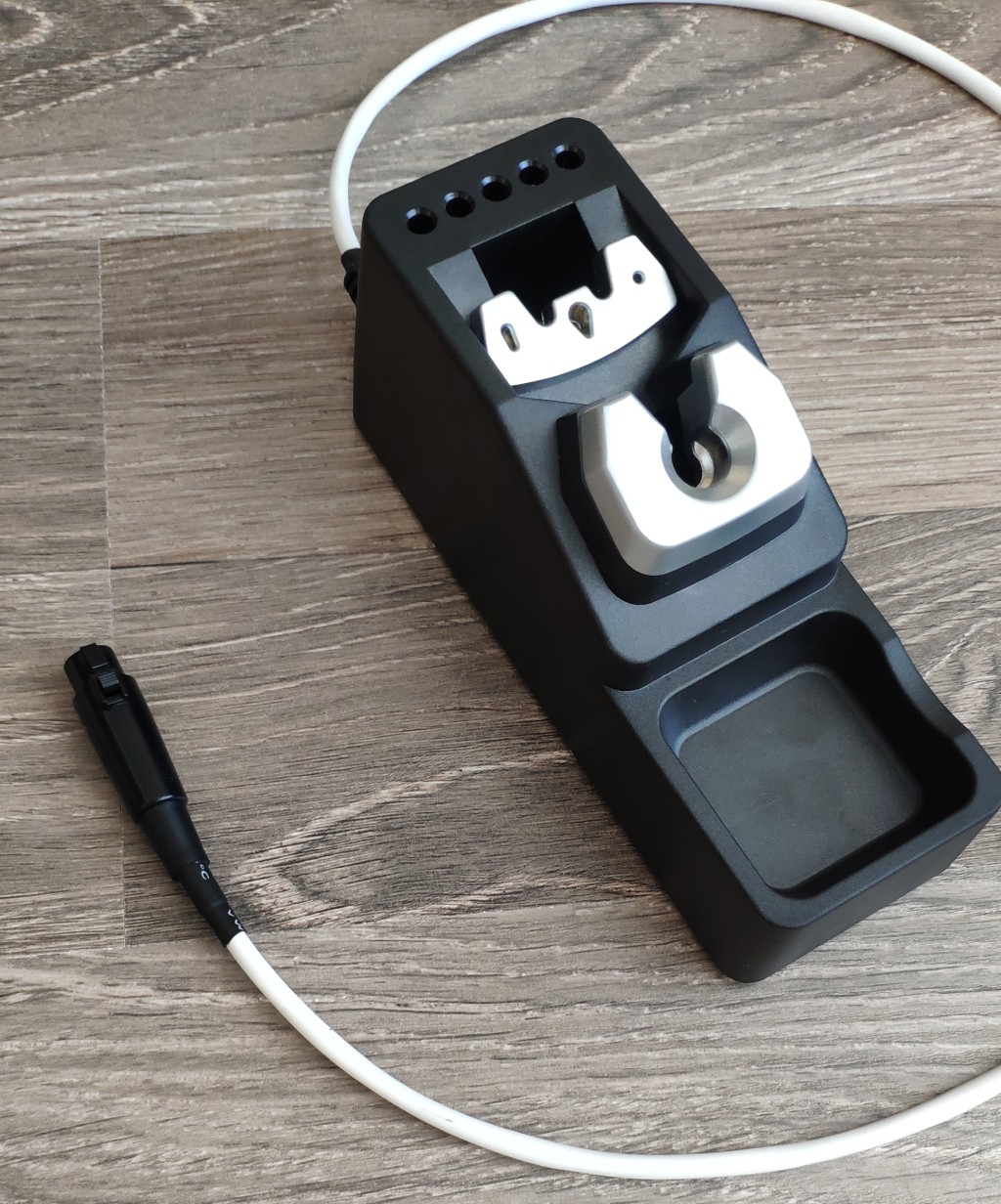
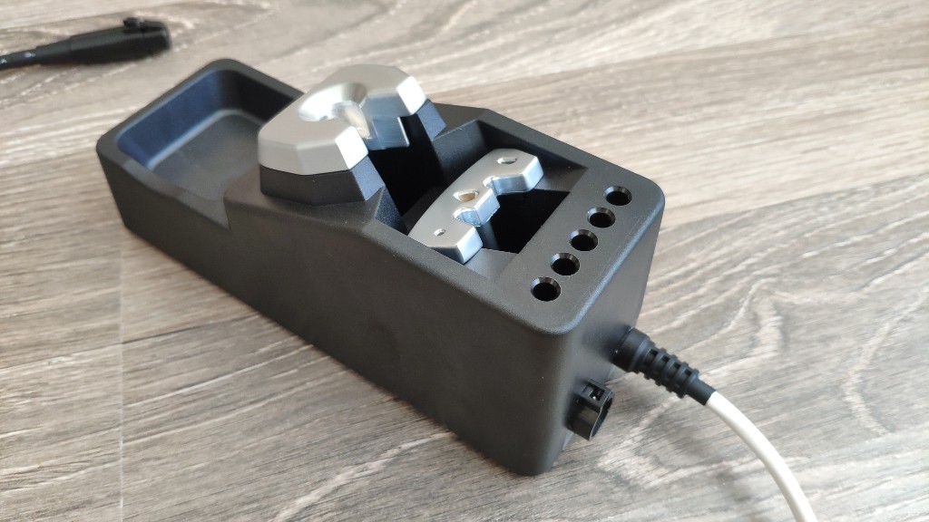
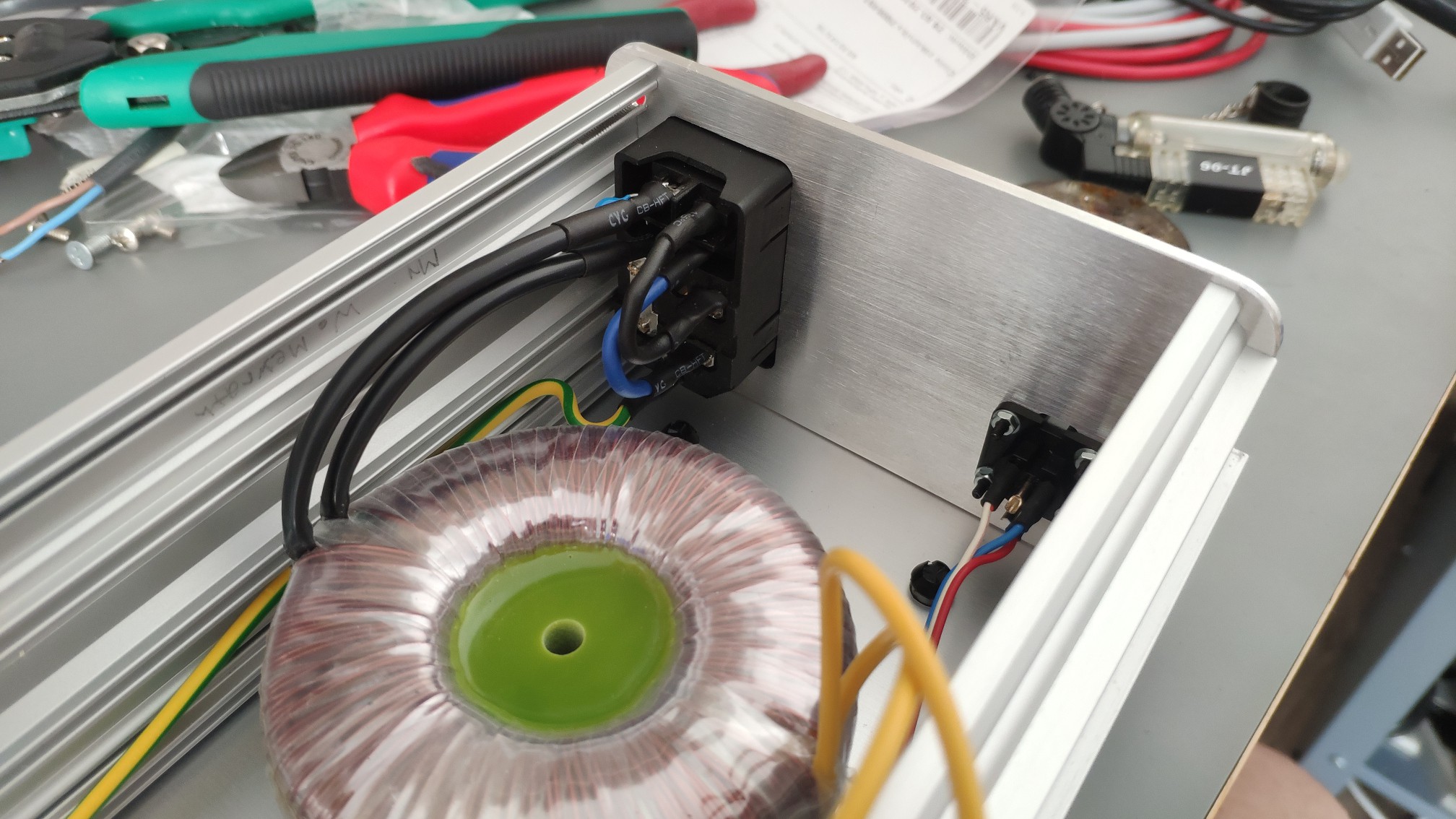
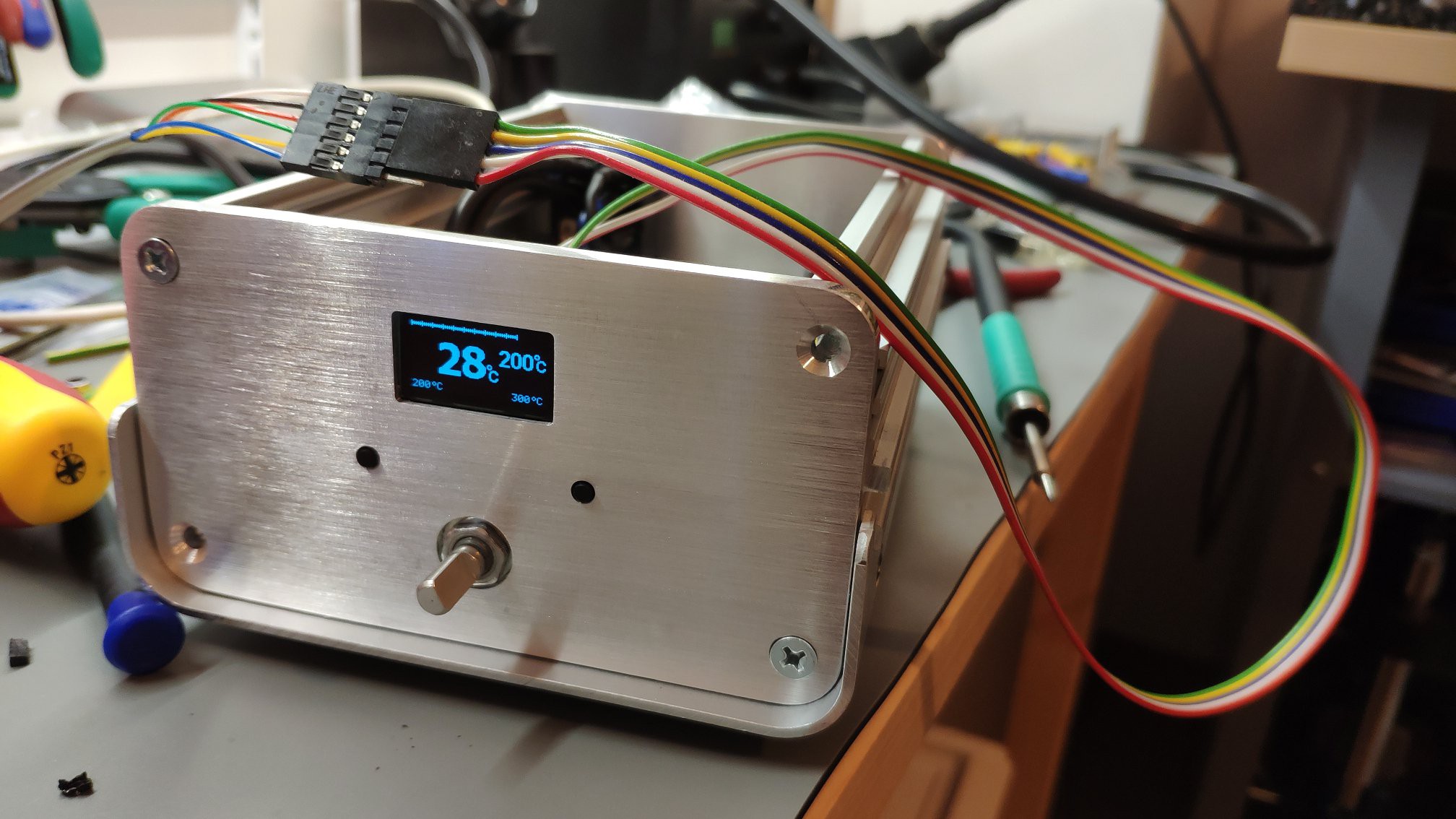
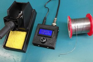
AndySoldering stations is based on 2-layer PCB, transformer and custom housing (future).
Power supply for pen 24V AC. There was a dilemma between power supply choosing, AC vs DC. There were prose and cons, like simpler switching, speed, saturation, isolation, temperature ... . After sum-up, I have chosen the AC one.
Basic concept:
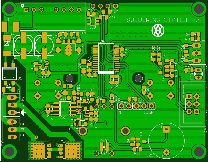
The soldering pen will be switched via 2 MOS-fets. One for positive and second one for negative part of AC signal. There were multiple options to control MOS-fets, like R+C, another transistor, SSR and so on. I have chosen opto-coupler with integrated MOS-fet driver. Anyway grounds needs to be isolated due to coupling and interference. One option was to chose transformer with two winding or isolated DC/DC converter.
When the pen will be turned off, thermo-electric voltage from thermo-coupler will be amplified and measured via OPAMP. A difference between target and actual value will be controlled over some kind of regulator, like PID.
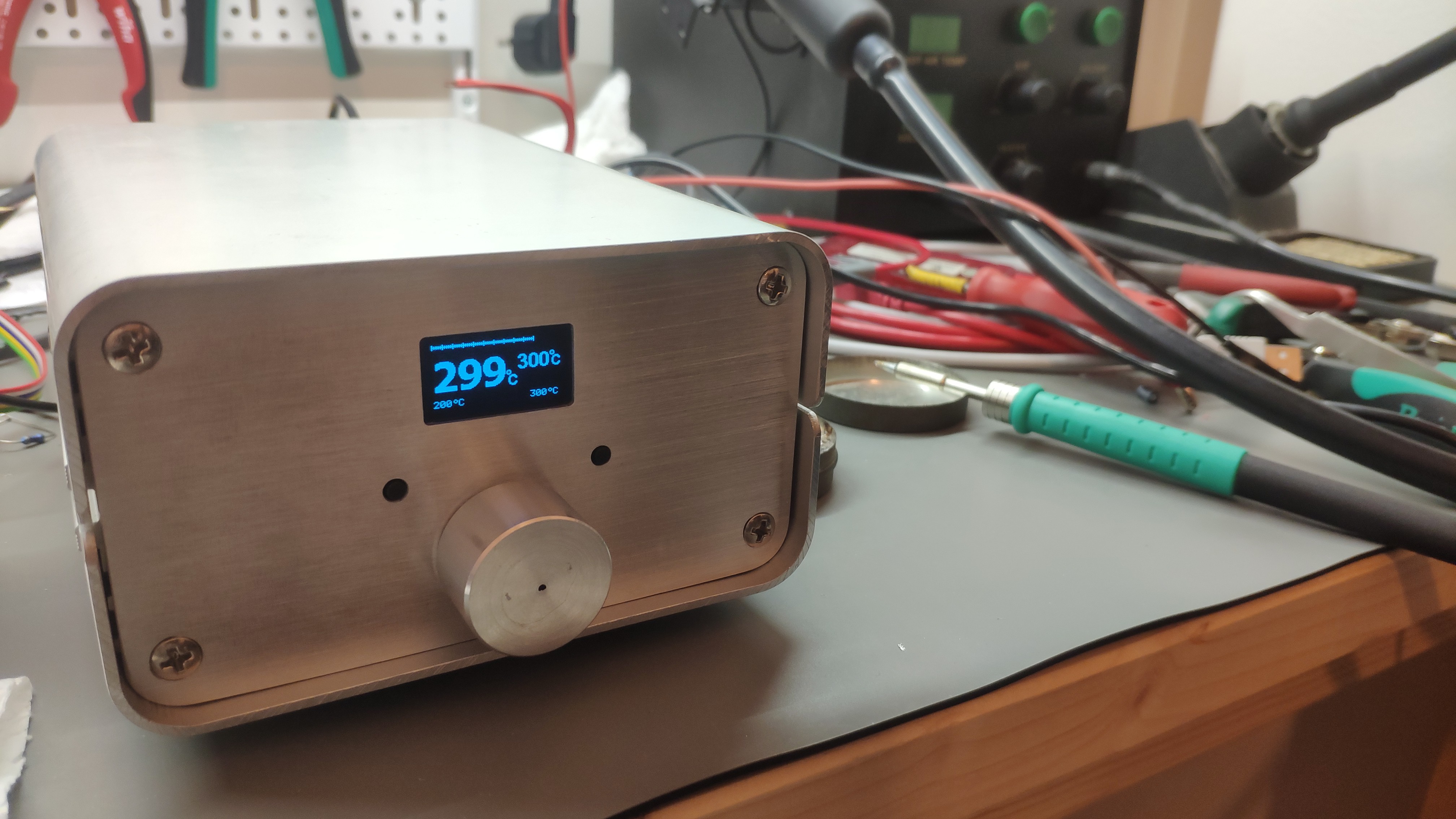
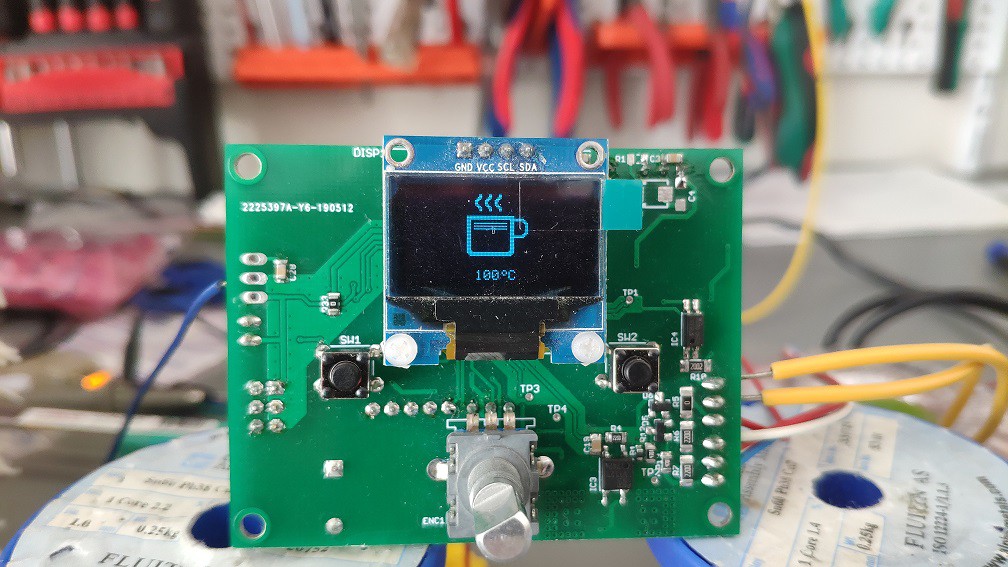
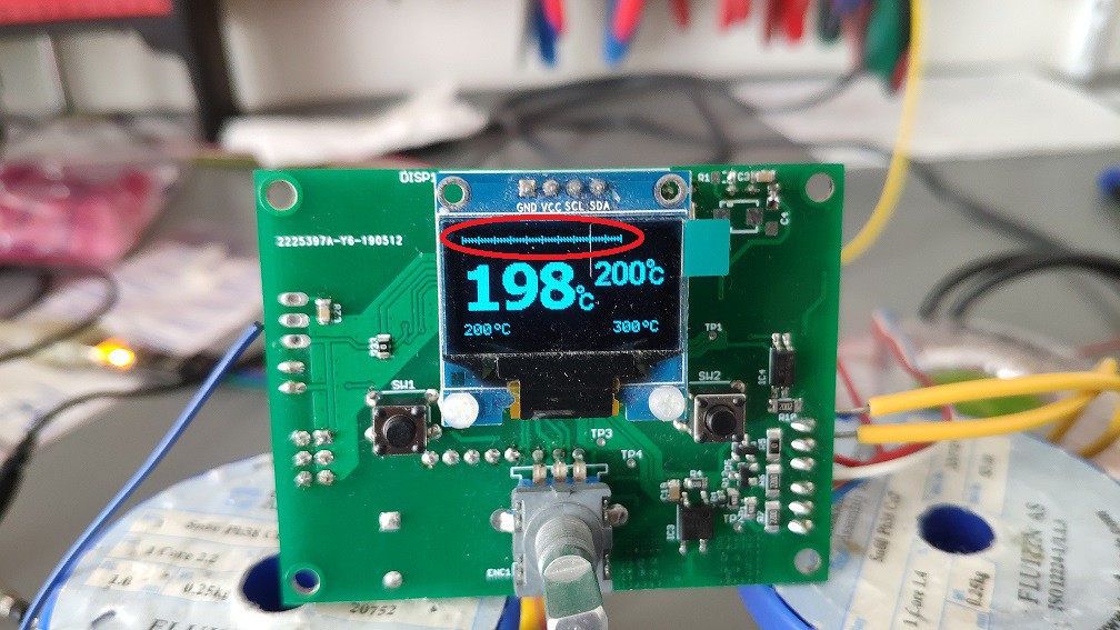
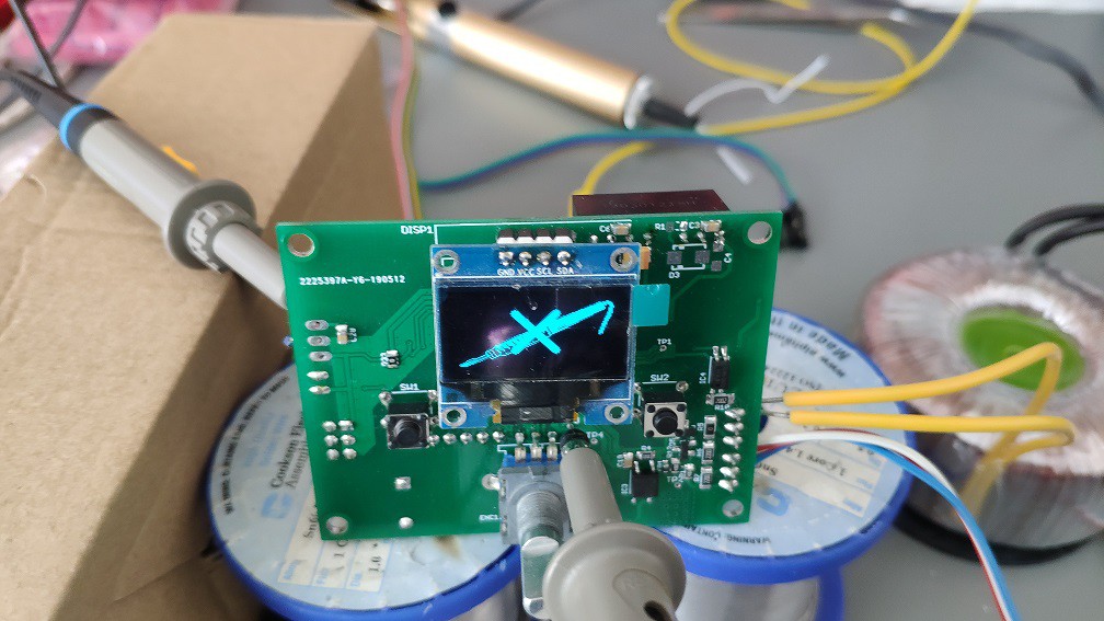
Device will be controlled from user-space over 2-switches (predefined quick temperature) and encoder (some settings). Response will be showed on OLED display.
Boards are now fabricated.
More details will be specified later, stay tuned... .
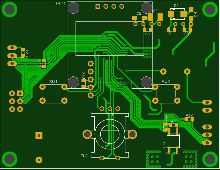
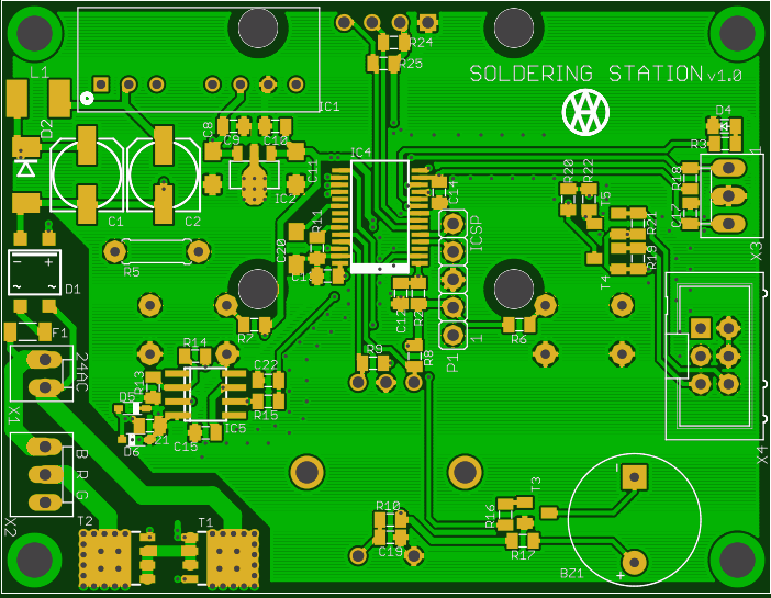
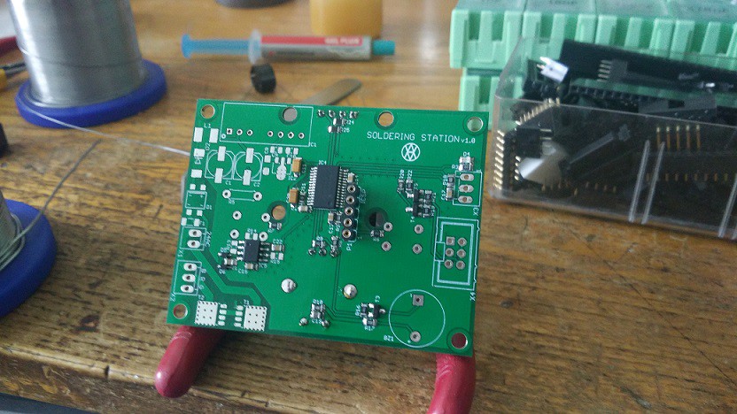
 Magic happened and PCBs are at home, finally... .
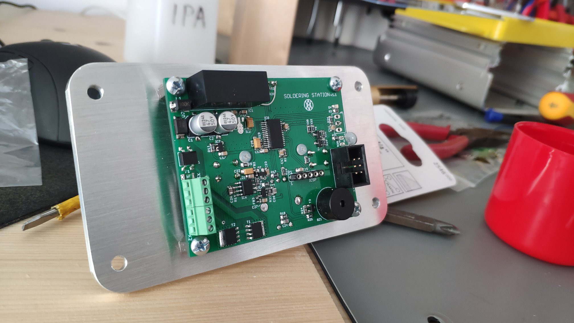
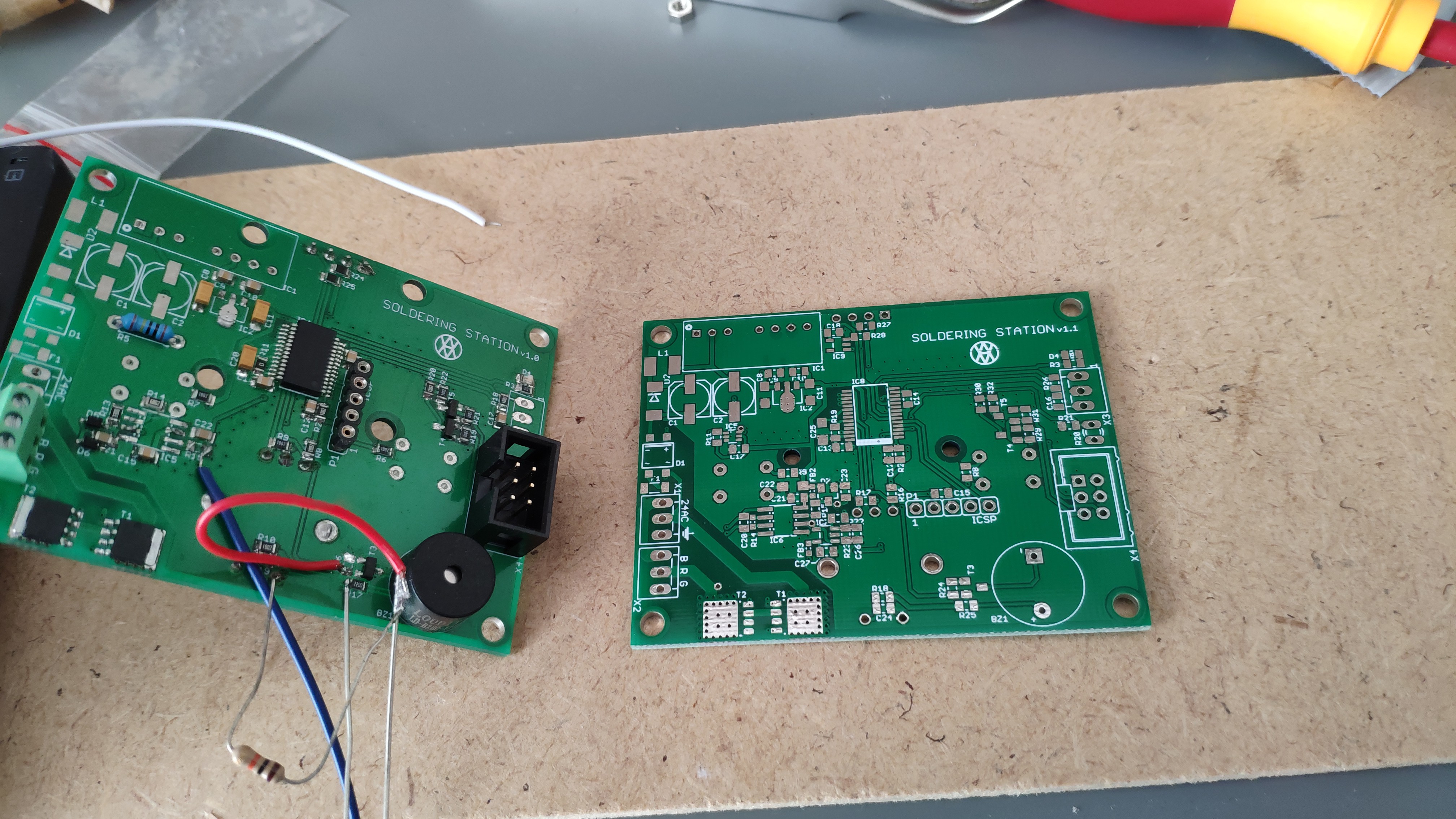 On the left side is version 1.0 and on the right side is new PCB version 1.1 .
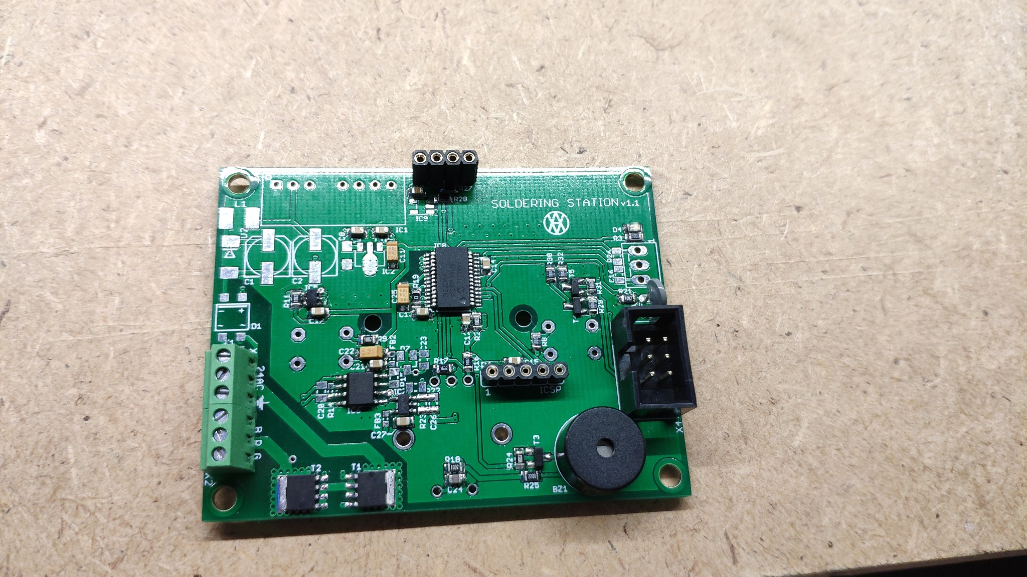 Some components has been taken from previous version. Finally "Hello world!" (LEDblinking) is working as well.
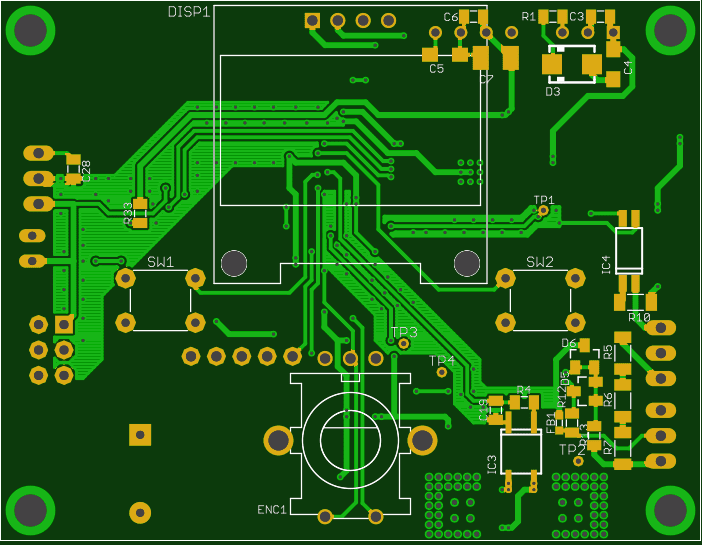


 Marius Taciuc
 Christine
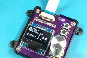
 CriptasticHacker
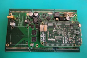
 Lucy Fauth
Hello, I assembled the board according to your project, but the firmware does not work correctly with the EEPROM, if the chip is soldered off, everything works without saving parameters, if I install a clean EEPROM, everything works before turning off, after turning on the heating temperature stops working and the soldering iron tip turns red.